User Manual
Page 3
... 1.2 Specifications 6 1.3 Motherboard Layout 8 1.4 ASRock I/O PlusTM 9 2 Installation 10 2.1 Screw Holes 10 2.2 Pre-installation Precautions 10 2.3 CPU Installation 11 2.4 Installation of CPU Fan and Heatsink 13 2.5 Installation of Memory Modules (DIMM 14 2.6 Expansion Slots (PCI and AGP Slots 15 2.7 Jumpers Setup 16 2.8 Onboard Headers and Connectors 17 2.9 Serial ATA (SATA) Hard Disks Installation 20 3 BIOS SETUP UTILITY 21 3.1 Introduction 21 3.1.1 BIOS Menu Bar 21 3.1.2 Navigation Keys 22 3.2 Main Screen 22 3.3 Advanced Screen 23 3.3.1 CPU Configuration 23 3.3.2 Chipset...
... 1.2 Specifications 6 1.3 Motherboard Layout 8 1.4 ASRock I/O PlusTM 9 2 Installation 10 2.1 Screw Holes 10 2.2 Pre-installation Precautions 10 2.3 CPU Installation 11 2.4 Installation of CPU Fan and Heatsink 13 2.5 Installation of Memory Modules (DIMM 14 2.6 Expansion Slots (PCI and AGP Slots 15 2.7 Jumpers Setup 16 2.8 Onboard Headers and Connectors 17 2.9 Serial ATA (SATA) Hard Disks Installation 20 3 BIOS SETUP UTILITY 21 3.1 Introduction 21 3.1.1 BIOS Menu Bar 21 3.1.2 Navigation Keys 22 3.2 Main Screen 22 3.3 Advanced Screen 23 3.3.1 CPU Configuration 23 3.3.2 Chipset...
User Manual
Page 5
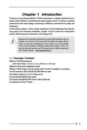
... , 30.5 cm x 18.3 cm) ASRock 775i48 Quick Installation Guide ASRock 775i48 Support CD (including LGA 775 CPU Installation Live Demo) One 80-conductor Ultra ATA 66/100 IDE Ribbon Cable One Ribbon Cable for purchasing ASRock 775i48 motherboard, a reliable motherboard produced under ASRock's consistently stringent quality control. ASRock website http://www.asrock.com 1.1 Package Contents ASRock 775i48 Motherboard (ATX Form Factor: 12.0-in x 7.2-in Floppy Drive One Serial ATA (SATA) Data Cable One Serial ATA (SATA) HDD Power Cable (Optional) One ASRock I/O PlusTM Shield 5 It delivers...
... , 30.5 cm x 18.3 cm) ASRock 775i48 Quick Installation Guide ASRock 775i48 Support CD (including LGA 775 CPU Installation Live Demo) One 80-conductor Ultra ATA 66/100 IDE Ribbon Cable One Ribbon Cable for purchasing ASRock 775i48 motherboard, a reliable motherboard produced under ASRock's consistently stringent quality control. ASRock website http://www.asrock.com 1.1 Package Contents ASRock 775i48 Motherboard (ATX Form Factor: 12.0-in x 7.2-in Floppy Drive One Serial ATA (SATA) Data Cable One Serial ATA (SATA) HDD Power Cable (Optional) One ASRock I/O PlusTM Shield 5 It delivers...
User Manual
Page 6
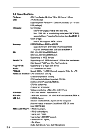
... DMA Mode 5 Supports up to 4 IDE devices Serial ATA: Supports up to 2 SATA devices at 1.5Gb/s data transfer rate (Not Support "RAID" and "Hot Plug" functions) Floppy Port: Supports up to 2 floppy disk drives Audio: 5.1 channels AC'97 Audio PCI LAN: Speed: 802.3u (10/100 Ethernet), supports Wake-On-LAN Hardware Monitor: CPU temperature sensing, Chassis temperature sensing, CPU overheat shutdown to protect CPU life (ASRock U-COP)(see CAUTION 4), CPU fan tachometer, Chassis fan tachometer, Voltage monitoring: +12V, +5V, +3.3V, Vcore PCI slots: 5 PCI slots with PCI Specification...
... DMA Mode 5 Supports up to 4 IDE devices Serial ATA: Supports up to 2 SATA devices at 1.5Gb/s data transfer rate (Not Support "RAID" and "Hot Plug" functions) Floppy Port: Supports up to 2 floppy disk drives Audio: 5.1 channels AC'97 Audio PCI LAN: Speed: 802.3u (10/100 Ethernet), supports Wake-On-LAN Hardware Monitor: CPU temperature sensing, Chassis temperature sensing, CPU overheat shutdown to protect CPU life (ASRock U-COP)(see CAUTION 4), CPU fan tachometer, Chassis fan tachometer, Voltage monitoring: +12V, +5V, +3.3V, Vcore PCI slots: 5 PCI slots with PCI Specification...

User Manual
Page 7
... over-clocking. Power Management for the memory support frequency and its corresponding CPU FSB frequency. BIOS: OS: AMI legal BIOS, Supports "Plug and Play", ACPI 1.1 compliance wake up events, Supports jumperfree, SMBIOS 2.3.1 support, CPU frequency stepless control (only for advanced users' reference, see page 16). 2. Before installing FSB1066 CPU, please make sure that you install the PC system. 5. Please check the table below for USB 2.0 works fine under Microsoft® Windows® 98/ ME. 7. CPU FSB Frequency Memory Support Frequency...
... over-clocking. Power Management for the memory support frequency and its corresponding CPU FSB frequency. BIOS: OS: AMI legal BIOS, Supports "Plug and Play", ACPI 1.1 compliance wake up events, Supports jumperfree, SMBIOS 2.3.1 support, CPU frequency stepless control (only for advanced users' reference, see page 16). 2. Before installing FSB1066 CPU, please make sure that you install the PC system. 5. Please check the table below for USB 2.0 works fine under Microsoft® Windows® 98/ ME. 7. CPU FSB Frequency Memory Support Frequency...

User Manual
Page 8
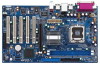
... ATA Connector (SATA2) 12 Clear CMOS Jumper (CLRCMOS0) 13 Chassis Fan Connector (CHA_FAN1) 14 USB 2.0 Header (USB67, Black) 15 System Panel Connector (PANEL1) 8 16 External Speaker Connector (SPEAKER1) 17 Infrared Module Connector (IR1) 18 Floppy Connector (FLOPPY1) 19 Game Connector (GAME1) 20 Internal Audio Connector: CD1 (Black) 21 Internal Audio Connector: AUX1 (White) 22 Front Panel Audio Connector (AUDIO1) 23 JR1 / JL1 Jumpers 24 PCI Slots (PCI1- 5) 25 Flash Memory 26 FSB Select Jumper (FSB1) 27 CPU Fan Connector (CPU_FAN1) 28 Shared USB 2.0 Header (USB4_5, Blue) 29 ATX Power Connector...
... ATA Connector (SATA2) 12 Clear CMOS Jumper (CLRCMOS0) 13 Chassis Fan Connector (CHA_FAN1) 14 USB 2.0 Header (USB67, Black) 15 System Panel Connector (PANEL1) 8 16 External Speaker Connector (SPEAKER1) 17 Infrared Module Connector (IR1) 18 Floppy Connector (FLOPPY1) 19 Game Connector (GAME1) 20 Internal Audio Connector: CD1 (Black) 21 Internal Audio Connector: AUX1 (White) 22 Front Panel Audio Connector (AUDIO1) 23 JR1 / JL1 Jumpers 24 PCI Slots (PCI1- 5) 25 Flash Memory 26 FSB Select Jumper (FSB1) 27 CPU Fan Connector (CPU_FAN1) 28 Shared USB 2.0 Header (USB4_5, Blue) 29 ATX Power Connector...
User Manual
Page 18
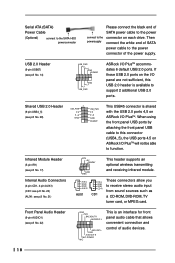
... power supply. If those USB 2.0 ports on ASRock I/O PlusTM will not be able to function. R MIC-POWER MIC This is shared with the USB 2.0 ports 4,5 on each drive. Serial ATA (SATA) Power Cable (Optional) connect to the SATA HDD power connector Please connect the black end of SATA power cable to the power connect to the connector on ASRock I/O PlusTM. O U T- Shared USB 2.0 Header (9-pin USB4_5) (see p.8 No. 22) GND +5VA BACKOUT-R BACKOUT-L 1 A U D - Then powersupply connect the white end of audio devices. 18 Front Panel Audio Header (9-pin...
... power supply. If those USB 2.0 ports on ASRock I/O PlusTM will not be able to function. R MIC-POWER MIC This is shared with the USB 2.0 ports 4,5 on each drive. Serial ATA (SATA) Power Cable (Optional) connect to the SATA HDD power connector Please connect the black end of SATA power cable to the power connect to the connector on ASRock I/O PlusTM. O U T- Shared USB 2.0 Header (9-pin USB4_5) (see p.8 No. 22) GND +5VA BACKOUT-R BACKOUT-L 1 A U D - Then powersupply connect the white end of audio devices. 18 Front Panel Audio Header (9-pin...
User Manual
Page 20
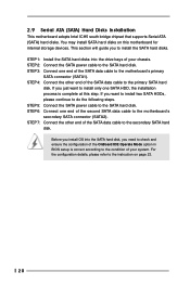
... your chassis. Before you to install only one end of the OnBoard IDE Operate Mode option in BIOS setup is complete at this motherboard for internal storage devices. 2.9 Serial ATA (SATA) Hard Disks Installation This motherboard adopts Intel ICH5 south bridge chipset that supports Serial ATA (SATA) hard disks. You may install SATA hard disks on page 23. 20 STEP 3: Connect one SATA HDD, the installation process is correct according to the condition of your system. STEP 5: Connect the SATA power cable to the motherboard's primary SATA connector (SATA1...
... your chassis. Before you to install only one end of the OnBoard IDE Operate Mode option in BIOS setup is complete at this motherboard for internal storage devices. 2.9 Serial ATA (SATA) Hard Disks Installation This motherboard adopts Intel ICH5 south bridge chipset that supports Serial ATA (SATA) hard disks. You may install SATA hard disks on page 23. 20 STEP 3: Connect one SATA HDD, the installation process is correct according to the condition of your system. STEP 5: Connect the SATA power cable to the motherboard's primary SATA connector (SATA1...
User Manual
Page 22
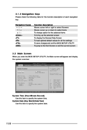
... screen 3.2 Main Screen When you enter the BIOS SETUP UTILITY, the Main screen will appear and display the system overview BIOS SETUP UTILITY Main Advanced H/W Monitor Boot Security Exit System Overview System Time System Date [14:00:09] [Wed 10/06/2004] BIOS Version : 775i48 BIOS P1.00 Processor Type : Intel (R) CPU 3.20GHz Processor Speed : 3200 MHz Cache Size : 1024KB Microcode Update : 0F34/QE Total Memory DIMM 1 DIMM 2 : 256MB : 256MB/166MHz (DDR333) : None Use [Enter], [TAB] or [SHIFT-TAB] to configure...
... screen 3.2 Main Screen When you enter the BIOS SETUP UTILITY, the Main screen will appear and display the system overview BIOS SETUP UTILITY Main Advanced H/W Monitor Boot Security Exit System Overview System Time System Date [14:00:09] [Wed 10/06/2004] BIOS Version : 775i48 BIOS P1.00 Processor Type : Intel (R) CPU 3.20GHz Processor Speed : 3200 MHz Cache Size : 1024KB Microcode Update : 0F34/QE Total Memory DIMM 1 DIMM 2 : 256MB : 256MB/166MHz (DDR333) : None Use [Enter], [TAB] or [SHIFT-TAB] to configure...
User Manual
Page 23
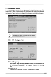
..., you may set the CPU host frequency. +F1 F9 F10 ESC Select Screen Select Item Change Option General Help Load Defaults Save and Exit Exit v02.54 (C) Copyright 1985-2003, American Megatrends, Inc. CPU Configuration Chipset Configuration ACPI Configuration IDE Configuration PCIPnP Configuration Floppy Configuration SuperIO Configuration USB Configuration Configure CPU Select Screen Select Item Enter Go to malfunction. CPU Host Frequency While entering setup, BIOS auto detects the present CPU host frequency of this motherboard. Main BIOS SETUP UTILITY Advanced H/W Monitor Boot Security...
..., you may set the CPU host frequency. +F1 F9 F10 ESC Select Screen Select Item Change Option General Help Load Defaults Save and Exit Exit v02.54 (C) Copyright 1985-2003, American Megatrends, Inc. CPU Configuration Chipset Configuration ACPI Configuration IDE Configuration PCIPnP Configuration Floppy Configuration SuperIO Configuration USB Configuration Configure CPU Select Screen Select Item Enter Go to malfunction. CPU Host Frequency While entering setup, BIOS auto detects the present CPU host frequency of this motherboard. Main BIOS SETUP UTILITY Advanced H/W Monitor Boot Security...
User Manual
Page 24
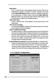
Hyper Threading Technology To enable this feature, it will be hidden if the current CPU does not support No-Excute Memory Protection. 3.3.2 Chipset Configuration BIOS SETUP UTILITY Advanced Chipset Configuration DRAM Frequency [Auto] Flexibility Option [Disabled] Configure DRAM Timing by malicious software to execute code. Ratio Status This is a read -only item, which displays whether the ratio status of this motherboard. If you use the ratio value to time the CPU frequency, it requires a computer system with...
Hyper Threading Technology To enable this feature, it will be hidden if the current CPU does not support No-Excute Memory Protection. 3.3.2 Chipset Configuration BIOS SETUP UTILITY Advanced Chipset Configuration DRAM Frequency [Auto] Flexibility Option [Disabled] Configure DRAM Timing by malicious software to execute code. Ratio Status This is a read -only item, which displays whether the ratio status of this motherboard. If you use the ratio value to time the CPU frequency, it requires a computer system with...
User Manual
Page 25
... to enable or disable the "OnBoard LAN" feature. Flexibility Option The default value of the PCI memory address range used for memory compatibility when it is set the value of this option is [Disabled]. Graphic Adapter Priority This allows you to select [PCI/AGP] and [AGP/PCI] as operating frequency: [133MHz (DDR 266)], [166MHz (DDR 333)], [200MHz (DDR 400)]. It is recommended to [Enabled]. DRAM Frequency If [Auto] is selected, the motherboard will configure...
... to enable or disable the "OnBoard LAN" feature. Flexibility Option The default value of the PCI memory address range used for memory compatibility when it is set the value of this option is [Disabled]. Graphic Adapter Priority This allows you to select [PCI/AGP] and [AGP/PCI] as operating frequency: [133MHz (DDR 266)], [166MHz (DDR 333)], [200MHz (DDR 400)]. It is recommended to [Enabled]. DRAM Frequency If [Auto] is selected, the motherboard will configure...
User Manual
Page 26
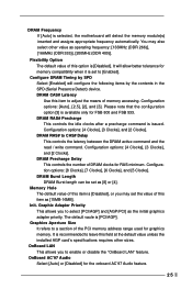
... disable the STR feature. +F1 F9 F10 ESC Select Screen Select Item Change Option General Help Load Defaults Save and Exit Exit v02.54 (C) Copyright 1985-2003, American Megatrends, Inc. If [Power Off] is selected, the AC/power resumes and the system starts to boot up when the power recovers. Restore on AC/Power Loss Use this feature if the OS supports it. 3.3.3 ACPI Configuration BIOS SETUP UTILITY Advanced ACPI Settings...
... disable the STR feature. +F1 F9 F10 ESC Select Screen Select Item Change Option General Help Load Defaults Save and Exit Exit v02.54 (C) Copyright 1985-2003, American Megatrends, Inc. If [Power Off] is selected, the AC/power resumes and the system starts to boot up when the power recovers. Restore on AC/Power Loss Use this feature if the OS supports it. 3.3.3 ACPI Configuration BIOS SETUP UTILITY Advanced ACPI Settings...
User Manual
Page 27
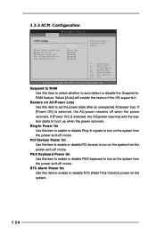
... following options will not work . When [Enhanced Mode] is installed into IDE HDD and SATA devices are used . +F1 F9 F10 ESC Select Screen Select Item Change Option General Help Load Defaults Save and Exit Exit v02.54 (C) Copyright 1985-2003, American Megatrends, Inc. Set to select [Compatible Mode]. Or you selected. 3.3.4 IDE Configuration BIOS SETUP UTILITY Advanced IDE Configuration OnBoard IDE Operate Mode OnBoard IDE Controller Primary IDE Master Primary IDE Slave Secondary IDE Master Secondary IDE Slave SATA1 SATA2 [Enhanced Mode] [Both] [Hard Disk] [Not...
... following options will not work . When [Enhanced Mode] is installed into IDE HDD and SATA devices are used . +F1 F9 F10 ESC Select Screen Select Item Change Option General Help Load Defaults Save and Exit Exit v02.54 (C) Copyright 1985-2003, American Megatrends, Inc. Set to select [Compatible Mode]. Or you selected. 3.3.4 IDE Configuration BIOS SETUP UTILITY Advanced IDE Configuration OnBoard IDE Operate Mode OnBoard IDE Controller Primary IDE Master Primary IDE Slave Secondary IDE Master Secondary IDE Slave SATA1 SATA2 [Enhanced Mode] [Both] [Hard Disk] [Not...

User Manual
Page 28
.... IDE Device Configuration You may set the partition of device connected to the system. +F1 F9 F10 ESC Select Screen Select Item Change Option General Help Load Defaults Save and Exit Exit v02.54 (C) Copyright 1985-2003, American Megatrends, Inc. Configuration options: [Not Installed], [Auto], [CD/DVD], and [ARMD]. [Not Installed]: Select [Not Installed] to disable the use of the IDE device that you specify. BIOS SETUP UTILITY Advanced Primary IDE Master Device Vendor Size LBA Mode Block Mode PIO Mode...
.... IDE Device Configuration You may set the partition of device connected to the system. +F1 F9 F10 ESC Select Screen Select Item Change Option General Help Load Defaults Save and Exit Exit v02.54 (C) Copyright 1985-2003, American Megatrends, Inc. Configuration options: [Not Installed], [Auto], [CD/DVD], and [ARMD]. [Not Installed]: Select [Not Installed] to disable the use of the IDE device that you specify. BIOS SETUP UTILITY Advanced Primary IDE Master Device Vendor Size LBA Mode Block Mode PIO Mode...
User Manual
Page 29
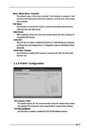
... Mode Use this item to set the PIO mode to enable or disable the PCI IDE BusMaster feature. 29 S.M.A.R.T. Configuration options: [Disabled], [Auto], [Enabled]. 32-Bit Data Transfer Use this item to enable 32-bit access to maximize the IDE hard disk data transfer rate. 3.3.5 PCIPnP Configuration BIOS SETUP UTILITY Advanced PCI / PnP Configuration PCI Latency Timer PCI IDE BusMaster [32] [Enabled] Value in units of this item to enhance hard disk performance by reading or writing more data during each transfer. PCI IDE BusMaster Use...
... Mode Use this item to set the PIO mode to enable or disable the PCI IDE BusMaster feature. 29 S.M.A.R.T. Configuration options: [Disabled], [Auto], [Enabled]. 32-Bit Data Transfer Use this item to enable 32-bit access to maximize the IDE hard disk data transfer rate. 3.3.5 PCIPnP Configuration BIOS SETUP UTILITY Advanced PCI / PnP Configuration PCI Latency Timer PCI IDE BusMaster [32] [Enabled] Value in units of this item to enhance hard disk performance by reading or writing more data during each transfer. PCI IDE BusMaster Use...
User Manual
Page 30
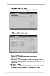
...OnBoard Floppy Controller Use this item to enable or disable floppy drive controller. Infrared Port Address Use this item to set the address for the onboard infrared port or disable it . Advanced BIOS SETUP UTILITY Floppy Configuration Floppy A Floppy B [1.44 MB 312"] [Disabled] Select the type of your floppy drive. Configuration options: [Disabled], [2F8 / IRQ3], and [2E8 / IRQ3]. 30 3.3.6 Floppy Configuration In this section, you may configure the type of floppy drive connected to the system. +F1 F9 F10 ESC Select Screen Select Item Change Option General Help Load Defaults...
...OnBoard Floppy Controller Use this item to enable or disable floppy drive controller. Infrared Port Address Use this item to set the address for the onboard infrared port or disable it . Advanced BIOS SETUP UTILITY Floppy Configuration Floppy A Floppy B [1.44 MB 312"] [Disabled] Select the type of your floppy drive. Configuration options: [Disabled], [2F8 / IRQ3], and [2E8 / IRQ3]. 30 3.3.6 Floppy Configuration In this section, you may configure the type of floppy drive connected to the system. +F1 F9 F10 ESC Select Screen Select Item Change Option General Help Load Defaults...
User Manual
Page 32
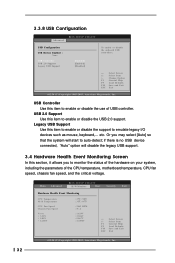
USB Controller Use this item to enable or disable the support to enable or disable the use of the CPU temperature, motherboard temperature, CPU fan speed, chassis fan speed, and the critical voltage. 32 Main Advanced BIOS SETUP UTILITY H/W Monitor Boot Security Exit Hardware Health Event Monitoring CPU Temperature M / B Temperature CPU Fan Speed Chassis Fan Speed Vcore + 3.30V + 5.00V + 12.00V : 37 C / 98 F : 31 C / 87 F : 2463 RPM : N/A : 1.629V : 3.306V : 5.067V : 11.890V F1 F9 F10 ESC Select Screen Select Item General Help Load Defaults Save and Exit Exit v02.54...
USB Controller Use this item to enable or disable the support to enable or disable the use of the CPU temperature, motherboard temperature, CPU fan speed, chassis fan speed, and the critical voltage. 32 Main Advanced BIOS SETUP UTILITY H/W Monitor Boot Security Exit Hardware Health Event Monitoring CPU Temperature M / B Temperature CPU Fan Speed Chassis Fan Speed Vcore + 3.30V + 5.00V + 12.00V : 37 C / 98 F : 31 C / 87 F : 2463 RPM : N/A : 1.629V : 3.306V : 5.067V : 11.890V F1 F9 F10 ESC Select Screen Select Item General Help Load Defaults Save and Exit Exit v02.54...
User Manual
Page 33
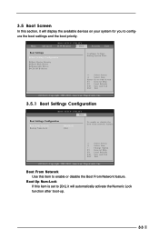
... Boot Boot Settings Configuration Boot From Network Bootup Num-Lock [Disabled] [On] To enable or disable the boot from network feature. +F1 F9 F10 ESC Select Screen Select Item Change Option General Help Load Defaults Save and Exit Exit v02.54 (C) Copyright 1985-2003, American Megatrends, Inc. Select Screen Select Item Enter Go to enable or disable the Boot From Network feature. Main Advanced BIOS SETUP UTILITY H/W Monitor Boot Security Exit Boot Settings Boot Settings Configuration Boot Device Priority Hard Disk Drives Removable Drives CD / DVD Drives Configure Settings...
... Boot Boot Settings Configuration Boot From Network Bootup Num-Lock [Disabled] [On] To enable or disable the boot from network feature. +F1 F9 F10 ESC Select Screen Select Item Change Option General Help Load Defaults Save and Exit Exit v02.54 (C) Copyright 1985-2003, American Megatrends, Inc. Select Screen Select Item Enter Go to enable or disable the Boot From Network feature. Main Advanced BIOS SETUP UTILITY H/W Monitor Boot Security Exit Boot Settings Boot Settings Configuration Boot Device Priority Hard Disk Drives Removable Drives CD / DVD Drives Configure Settings...
User Manual
Page 34
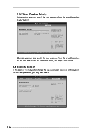
... hard disk drives, the removable drives, and the CD/DVD drives. 3.6 Security Screen In this section, you may specify the boot sequence from the available devices in the corresponding type menu. +F1 F9 F10 ESC Select Screen Select Item Change Option General Help Load Defaults Save and Exit Exit v02.54 (C) Copyright 1985-2003, American Megatrends, Inc. Likewise, you may also clear it. Main Advanced BIOS SETUP UTILITY H/W Monitor Boot Security Exit Security Settings Supervisor Password...
... hard disk drives, the removable drives, and the CD/DVD drives. 3.6 Security Screen In this section, you may specify the boot sequence from the available devices in the corresponding type menu. +F1 F9 F10 ESC Select Screen Select Item Change Option General Help Load Defaults Save and Exit Exit v02.54 (C) Copyright 1985-2003, American Megatrends, Inc. Likewise, you may also clear it. Main Advanced BIOS SETUP UTILITY H/W Monitor Boot Security Exit Security Settings Supervisor Password...
User Manual
Page 36
... Refer to your CD-ROM drive. You can run Microsoft® Media Player® to display the menus. 4.2.2 Drivers Menu The Drivers Menu shows the available devices drivers if the system detects installed devices. To see this chapter for more about ASRock, welcome to visit ASRock's website at http://www.asrock.com; Because motherboard settings and hardware options vary, use the setup procedures in the Support CD to play the...
... Refer to your CD-ROM drive. You can run Microsoft® Media Player® to display the menus. 4.2.2 Drivers Menu The Drivers Menu shows the available devices drivers if the system detects installed devices. To see this chapter for more about ASRock, welcome to visit ASRock's website at http://www.asrock.com; Because motherboard settings and hardware options vary, use the setup procedures in the Support CD to play the...


