
User Manual
Page 4
... information. Chapter 1 Introduction Thank you for Floppy Drive (1 x Ribbon Cable) 1 ASRock I/OTM Shield 1 COM Port Bracket (2 COM Port Bracket is optional) 1 ASRock MR Card (Optional) 4 ASRock website http://www.asrock.com 1.1 Package Contents ASRock 775i45GV Motherboard (Micro ATX form factor: 9.6" x 8.5", 24.4 x 21.6 cm) ASRock 775i45GV Quick Installation Guide ASRock Intel-Intel Support CD (including LGA 775 CPU Installation Live Demo) 1 Cable...
... information. Chapter 1 Introduction Thank you for Floppy Drive (1 x Ribbon Cable) 1 ASRock I/OTM Shield 1 COM Port Bracket (2 COM Port Bracket is optional) 1 ASRock MR Card (Optional) 4 ASRock website http://www.asrock.com 1.1 Package Contents ASRock 775i45GV Motherboard (Micro ATX form factor: 9.6" x 8.5", 24.4 x 21.6 cm) ASRock 775i45GV Quick Installation Guide ASRock Intel-Intel Support CD (including LGA 775 CPU Installation Live Demo) 1 Cable...

User Manual
Page 5
..., Vcore; Supports "Plug and Play"; IDE2: ATA 100 / Ultra DMA Mode 5; CPU fan tachometer; ACPI 1.1 compliance wake up to protect CPU life (ASRock U-COP) (see CAUTION 1) South Bridge: Intel® ICH4 Intel® Extreme Graphics, Max. 64MB VRAM Memory: 2 DDR DIMM slots, DDR1 and DDR2 supports PC2700 (DDR333) / PC2100 (DDR266), Max. 2GB IDE...
..., Vcore; Supports "Plug and Play"; IDE2: ATA 100 / Ultra DMA Mode 5; CPU fan tachometer; ACPI 1.1 compliance wake up to protect CPU life (ASRock U-COP) (see CAUTION 1) South Bridge: Intel® ICH4 Intel® Extreme Graphics, Max. 64MB VRAM Memory: 2 DDR DIMM slots, DDR1 and DDR2 supports PC2700 (DDR333) / PC2100 (DDR266), Max. 2GB IDE...

User Manual
Page 9
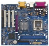
... Ports USB 2.0 Ports Line out LiLInnineein MMIniicc in IR1 Super I/O AUDIO1 1 JR1 JL1 AUDIO CODEC Intel PCI 845GV LAN Chipset Clock Gen AGP1 PCI 1 775i45GV PCI 2 ` PCI 3 AMR1 FLOPPY1 2MB BIOS IDE2 IDE1 01 23 Intel ICH4 CMOS Battery CLRCMOS0 CHA_FAN1 USB45 1 1 SPEAKER1 1 PLED PWRBTN PANEL 1 1 1 COM1 HDLED RST...(FLOPPY1) 19 AMR Slot (AMR1) 20 JR1 / JL1 Jumpers 21 Front Panel Audio Connector (AUDIO1) 22 PCI Slots (PCI1- 3) 23 ASRock Graphics Interface Slot 24 Infrared Module Header (IR1) 25 Internal Audio Connector: CD1 (Black) 26 Internal Audio Connector: AUX1 (White) 9
... Ports USB 2.0 Ports Line out LiLInnineein MMIniicc in IR1 Super I/O AUDIO1 1 JR1 JL1 AUDIO CODEC Intel PCI 845GV LAN Chipset Clock Gen AGP1 PCI 1 775i45GV PCI 2 ` PCI 3 AMR1 FLOPPY1 2MB BIOS IDE2 IDE1 01 23 Intel ICH4 CMOS Battery CLRCMOS0 CHA_FAN1 USB45 1 1 SPEAKER1 1 PLED PWRBTN PANEL 1 1 1 COM1 HDLED RST...(FLOPPY1) 19 AMR Slot (AMR1) 20 JR1 / JL1 Jumpers 21 Front Panel Audio Connector (AUDIO1) 22 PCI Slots (PCI1- 3) 23 ASRock Graphics Interface Slot 24 Infrared Module Header (IR1) 25 Internal Audio Connector: CD1 (Black) 26 Internal Audio Connector: AUX1 (White) 9

User Manual
Page 12
... depressing down and out on the socket. Rotate the load plate to fully open position at approximately 100 degrees. 2.3 CPU Installation For the installation of Intel 775-Pin CPU, please follow the steps below. 775-Pin Socket Overview Before you insert the 775-Pin CPU into the socket if above situation...
... depressing down and out on the socket. Rotate the load plate to fully open position at approximately 100 degrees. 2.3 CPU Installation For the installation of Intel 775-Pin CPU, please follow the steps below. 775-Pin Socket Overview Before you insert the 775-Pin CPU into the socket if above situation...

User Manual
Page 14
...with the motherboard throughholes. For proper installation, please kindly refer to the instruction manuals of IHS on the socket surface. Align fasteners with Intel 775-Pin CPU to dissipate heat. Step 5. Secure excess cable with tie-wrap to ensure cable does not interfere with the CPU fan...the installation of the heatsink for 775-Pin CPU. Before you installed the heatsink, you press down on the motherboard. Ensure that supports Intel 775-Pin CPU. Below is equipped with each other components. 14 Place the heatsink onto the socket. Rotate the fastener clockwise, then press...
...with the motherboard throughholes. For proper installation, please kindly refer to the instruction manuals of IHS on the socket surface. Align fasteners with Intel 775-Pin CPU to dissipate heat. Step 5. Secure excess cable with tie-wrap to ensure cable does not interfere with the CPU fan...the installation of the heatsink for 775-Pin CPU. Before you installed the heatsink, you press down on the motherboard. Ensure that supports Intel 775-Pin CPU. Below is equipped with each other components. 14 Place the heatsink onto the socket. Rotate the fastener clockwise, then press...

User Manual
Page 21
... 3.31a Security Power Boot Exit Sep 01 2004 Wed 16:07:40 [ Setup Help ] Month: Jan - Dec Day: 01 - 31 Year: 1980 - 2099 775i45GV BIOS P1.00 Intel (R) CPU 2933 MHz 256 KB F41 / 05 1024 MB with 8MB Shared Memory 512 MB / 166 MHz (DDR333) 512 MB / 166 MHz (DDR333) F1...
... 3.31a Security Power Boot Exit Sep 01 2004 Wed 16:07:40 [ Setup Help ] Month: Jan - Dec Day: 01 - 31 Year: 1980 - 2099 775i45GV BIOS P1.00 Intel (R) CPU 2933 MHz 256 KB F41 / 05 1024 MB with 8MB Shared Memory 512 MB / 166 MHz (DDR333) 512 MB / 166 MHz (DDR333) F1...

User Manual
Page 24
...drivers and useful utilities that Intel has released. Please install the necessary drivers to display the menus. 4.2.2 Drivers Menu The Drivers Menu shows the available devices drivers if the system detects installed devices. To see this demo program, you need to contact ASRock or want to know more... information. 4.2 Support CD Information The Support CD that came with Intel LGA 775 socket, which is enabled in your dealer for further information. 24 Because motherboard...
...drivers and useful utilities that Intel has released. Please install the necessary drivers to display the menus. 4.2.2 Drivers Menu The Drivers Menu shows the available devices drivers if the system detects installed devices. To see this demo program, you need to contact ASRock or want to know more... information. 4.2 Support CD Information The Support CD that came with Intel LGA 775 socket, which is enabled in your dealer for further information. 24 Because motherboard...

User Manual
Page 25
... menus: "Advanced," "Security," "Power," "Boot," and "Exit." 1. Appendix: Advanced BIOS Setup This section will be [Disabled] for this feature, it requires a computer system with an Intel Pentium®4 processor that supports Hyper-Threading technology and an operating system that times the frontside bus frequency will detect the memory module(s) inserted and...
... menus: "Advanced," "Security," "Power," "Boot," and "Exit." 1. Appendix: Advanced BIOS Setup This section will be [Disabled] for this feature, it requires a computer system with an Intel Pentium®4 processor that supports Hyper-Threading technology and an operating system that times the frontside bus frequency will detect the memory module(s) inserted and...

User Manual
Page 27
... ] PCI Latency Timer (PCI Clocks) 32 Primary Graphics Adapter PPCCII to enable or disable the floppy drive controller. We recommend you to the IA-32 Intel Architecture. VERSION 3.31a Peripheral Configuration [ Setup Help ] OnBoard FDC OnBoard Serial Port OnBoard Infrared Port OnBoard Parallel Port Parallel Port Mode EPP Version Parallel Port...
... ] PCI Latency Timer (PCI Clocks) 32 Primary Graphics Adapter PPCCII to enable or disable the floppy drive controller. We recommend you to the IA-32 Intel Architecture. VERSION 3.31a Peripheral Configuration [ Setup Help ] OnBoard FDC OnBoard Serial Port OnBoard Infrared Port OnBoard Parallel Port Parallel Port Mode EPP Version Parallel Port...


