User Manual
Page 3
...16 2.7 Jumpers Setup 17 2.8 Onboard Headers and Connectors 18 2.9 Serial ATA (SATA) Hard Disks Installation 21 2.10 Hot Plug and Hot Swap Functions for SATA HDDs .... 21 2.11 Installing Windows 2000 / Windows XP / Windows XP 64-bit With RAID Functions 22 2.12 Installing Windows 98 / ME / 2000 / XP / XP 64-bit Without RAID Functions 23 3. BIOS SETUP UTILITY 24 3.1 Introduction 24 3.1.1 BIOS Menu Bar 24 3.1.2 Navigation Keys 25 3.2 Main Screen 25 3.3 Advanced Screen 25 3.3.1 CPU Configuration 26 3.3.2 Chipset Configuration 28 3.3.3 ACPI Configuration 32 3.3.4 IDE Configuration 33...
...16 2.7 Jumpers Setup 17 2.8 Onboard Headers and Connectors 18 2.9 Serial ATA (SATA) Hard Disks Installation 21 2.10 Hot Plug and Hot Swap Functions for SATA HDDs .... 21 2.11 Installing Windows 2000 / Windows XP / Windows XP 64-bit With RAID Functions 22 2.12 Installing Windows 98 / ME / 2000 / XP / XP 64-bit Without RAID Functions 23 3. BIOS SETUP UTILITY 24 3.1 Introduction 24 3.1.1 BIOS Menu Bar 24 3.1.2 Navigation Keys 25 3.2 Main Screen 25 3.3 Advanced Screen 25 3.3.1 CPU Configuration 26 3.3.2 Chipset Configuration 28 3.3.3 ACPI Configuration 32 3.3.4 IDE Configuration 33...
User Manual
Page 5
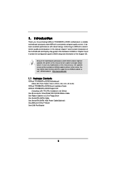
....asrock.com 1.1 Package Contents ASRock 775VM800Pro-DDR2 Motherboard (Micro ATX Form Factor: 9.6-in x 8.5-in Floppy Drive One Serial ATA (SATA) Cable One Serial ATA (SATA) HDD Power Cable(Optional) One ASRock I/O PlusTM Shield One COM Port Bracket 5 Because the motherboard specifications and the BIOS software might be updated, the content of this manual, chapter 1 and 2 contain introduction of the Support CD. Introduction Thank you for a 3.5-in , 24.4 cm x 21.6 cm) ASRock 775VM800Pro-DDR2 Quick Installation Guide ASRock 775VM800Pro-DDR2 Support CD (including LGA 775 CPU Installation...
....asrock.com 1.1 Package Contents ASRock 775VM800Pro-DDR2 Motherboard (Micro ATX Form Factor: 9.6-in x 8.5-in Floppy Drive One Serial ATA (SATA) Cable One Serial ATA (SATA) HDD Power Cable(Optional) One ASRock I/O PlusTM Shield One COM Port Bracket 5 Because the motherboard specifications and the BIOS software might be updated, the content of this manual, chapter 1 and 2 contain introduction of the Support CD. Introduction Thank you for a 3.5-in , 24.4 cm x 21.6 cm) ASRock 775VM800Pro-DDR2 Quick Installation Guide ASRock 775VM800Pro-DDR2 Support CD (including LGA 775 CPU Installation...
User Manual
Page 7
... in header - CPU Temperature Sensing - Chassis Temperature Sensing - CPU Fan Tachometer - CD in header - AMI Legal BIOS - ACPI 1.1 Compliance Wake Up Events - Connector BIOS Feature Support CD Hardware Monitor OS Certifications - 2 x Serial ATA 1.5Gb/s connectors (Supports RAID 0, 1, JBOD and "Hot Plug" functions) - 2 x ATA133 IDE connector (supports 4 x IDE devices) - 1 x Floppy connector - 1 x COM port header - 1 x IR header - Supports "Plug and Play" - Voltage Monitoring: +12V, +5V, +3.3V, Vcore - CPU/Chassis FAN connector - 20 pin ATX power connector - 4 pin 12V power...
... in header - CPU Temperature Sensing - Chassis Temperature Sensing - CPU Fan Tachometer - CD in header - AMI Legal BIOS - ACPI 1.1 Compliance Wake Up Events - Connector BIOS Feature Support CD Hardware Monitor OS Certifications - 2 x Serial ATA 1.5Gb/s connectors (Supports RAID 0, 1, JBOD and "Hot Plug" functions) - 2 x ATA133 IDE connector (supports 4 x IDE devices) - 1 x Floppy connector - 1 x COM port header - 1 x IR header - Supports "Plug and Play" - Voltage Monitoring: +12V, +5V, +3.3V, Vcore - CPU/Chassis FAN connector - 20 pin ATX power connector - 4 pin 12V power...

User Manual
Page 8
... perform over-clocking. Power Management for USB 2.0 works fine under Microsoft® Windows® 98 / ME. 8 While CPU overheat is not recommended to spray thermal grease between the CPU and the heatsink when you resume the system, please check if the CPU fan on the AGP slot of this motherboard offers stepless control, it back again. Do NOT use a 3.3V AGP card on the motherboard functions...
... perform over-clocking. Power Management for USB 2.0 works fine under Microsoft® Windows® 98 / ME. 8 While CPU overheat is not recommended to spray thermal grease between the CPU and the heatsink when you resume the system, please check if the CPU fan on the AGP slot of this motherboard offers stepless control, it back again. Do NOT use a 3.3V AGP card on the motherboard functions...

User Manual
Page 9
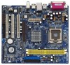
... / JL1 Jumpers 22 Front Panel Audio Header (AUDIO1) 23 Internal Audio Connector: CD1 (Black) 24 Internal Audio Connector: AUX1 (White) 25 3 x PCI Slots (PCI1- 3) 26 Flash Memory 27 Serial Port Connector (COM1) 28 Infrared Module Header (IR1) 29 Shared USB 2.0 Header (USB4_5, Blue) 9 1.3 Motherboard Layout 1 234 PS2 Mouse PS2_US1 B_PWR1 ATX12V1 5 6 7 21.6cm (8.5 in) 24.4cm (9.6 in) Dual Core CPU DDRII_1 (64/72 bit, 240-pin module) DDRII_2 (64/72 bit, 240-pin module) DDRII533 PARALLEL PORT PS2 Keyboard VGA1 CPU_FAN1...
... / JL1 Jumpers 22 Front Panel Audio Header (AUDIO1) 23 Internal Audio Connector: CD1 (Black) 24 Internal Audio Connector: AUX1 (White) 25 3 x PCI Slots (PCI1- 3) 26 Flash Memory 27 Serial Port Connector (COM1) 28 Infrared Module Header (IR1) 29 Shared USB 2.0 Header (USB4_5, Blue) 9 1.3 Motherboard Layout 1 234 PS2 Mouse PS2_US1 B_PWR1 ATX12V1 5 6 7 21.6cm (8.5 in) 24.4cm (9.6 in) Dual Core CPU DDRII_1 (64/72 bit, 240-pin module) DDRII_2 (64/72 bit, 240-pin module) DDRII533 PARALLEL PORT PS2 Keyboard VGA1 CPU_FAN1...
User Manual
Page 19
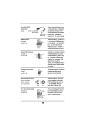
.... USB 2.0 Header (9-pin USB67) (see p.9, No. 18) USB_PWR P-7 P+7 GND DUMMY 1 GND P+6 P-6 USB_PWR ASRock I /O PlusTM will not be able to receive stereo audio input from sound sources such as a CD-ROM, DVD-ROM, TV tuner card, or MPEG card. This header supports an optional wireless transmitting and receiving infrared module. O U T- If the rear USB ports are not sufficient, this connector (USB4_5), the USB ports 4,5 on the rear panel. Serial ATA (SATA) Power Cable (Optional) connect to the SATA HDD power connector connect...
.... USB 2.0 Header (9-pin USB67) (see p.9, No. 18) USB_PWR P-7 P+7 GND DUMMY 1 GND P+6 P-6 USB_PWR ASRock I /O PlusTM will not be able to receive stereo audio input from sound sources such as a CD-ROM, DVD-ROM, TV tuner card, or MPEG card. This header supports an optional wireless transmitting and receiving infrared module. O U T- If the rear USB ports are not sufficient, this connector (USB4_5), the USB ports 4,5 on the rear panel. Serial ATA (SATA) Power Cable (Optional) connect to the SATA HDD power connector connect...
User Manual
Page 20
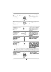
... pin. Chassis Fan Connector (3-pin CHA_FAN1) (see p.9, No. 13) CPU Fan Connector (4-pin CPU_FAN1) (see p.9, No. 3) ATX Power Connector (20-pin ATXPWR1) (see p.9, No. 2) Please note that it is necessary to connect a power supply with ATX 12V plug to this header. ATX 12V Connector (4-pin ATX12V1) (see p.9, No. 4) GND +12V CHA_FAN_SPEED Please connect the chassis fan cable to this connector so that it may cause permanent damage! Serial port connector (9-pin COM1) (see p.9, No. 17) PLED+ PLEDPWRBTN# GND 1 DUMMY RESET# GND HDLEDHDLED+ 1 SPEAKER...
... pin. Chassis Fan Connector (3-pin CHA_FAN1) (see p.9, No. 13) CPU Fan Connector (4-pin CPU_FAN1) (see p.9, No. 3) ATX Power Connector (20-pin ATXPWR1) (see p.9, No. 2) Please note that it is necessary to connect a power supply with ATX 12V plug to this header. ATX 12V Connector (4-pin ATX12V1) (see p.9, No. 4) GND +12V CHA_FAN_SPEED Please connect the chassis fan cable to this connector so that it may cause permanent damage! Serial port connector (9-pin COM1) (see p.9, No. 17) PLED+ PLEDPWRBTN# GND 1 DUMMY RESET# GND HDLEDHDLED+ 1 SPEAKER...
User Manual
Page 22
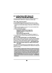
... boot devices selection appears. STEP 2: Use "RAID Installation Guide" to format and copy files [YN]? After making a SATA driver diskette and using "RAID Installation Guid" to set RAID configuration. C. WARNING! Start to set RAID configuration, you want to generate Serial ATA driver diskette [YN]?", press . Please insert a floppy diskette into the floppy drive. When you see these messages, Please insert a diskette into the floppy drive, and press . Please refer to the document in the Support CD, "Guide to SATA Hard Disks Installation and RAID Configuration...
... boot devices selection appears. STEP 2: Use "RAID Installation Guide" to format and copy files [YN]? After making a SATA driver diskette and using "RAID Installation Guid" to set RAID configuration. C. WARNING! Start to set RAID configuration, you want to generate Serial ATA driver diskette [YN]?", press . Please insert a floppy diskette into the floppy drive. When you see these messages, Please insert a diskette into the floppy drive, and press . Please refer to the document in the Support CD, "Guide to SATA Hard Disks Installation and RAID Configuration...
User Manual
Page 25
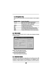
... Configuration, ACPI Configuration, IDE Configuration, PCIPnP Configuration, Floppy Configuration, SuperIO Configuration, and USB Configuration. 25 Use [+] or [-] to select a field. System Time [Hour:Minute:Second] Use this section, you enter the BIOS SETUP UTILITY, the Main screen will appear and display the system overview BIOS SETUP UTILITY Main Advanced H/W Monitor Boot Security Exit System Overview System Time System Date [17:00:09] [Tue 09/27/2005] BIOS Version : 775VM800Pro-DDR2 BIOS P1.00 Processor Type : Intel (R) CPU 3.20 GHz Processor Speed : 3200 MHz Cache Size...
... Configuration, ACPI Configuration, IDE Configuration, PCIPnP Configuration, Floppy Configuration, SuperIO Configuration, and USB Configuration. 25 Use [+] or [-] to select a field. System Time [Hour:Minute:Second] Use this section, you enter the BIOS SETUP UTILITY, the Main screen will appear and display the system overview BIOS SETUP UTILITY Main Advanced H/W Monitor Boot Security Exit System Overview System Time System Date [17:00:09] [Tue 09/27/2005] BIOS Version : 775VM800Pro-DDR2 BIOS P1.00 Processor Type : Intel (R) CPU 3.20 GHz Processor Speed : 3200 MHz Cache Size...
User Manual
Page 26
..., American Megatrends, Inc. Boot Failure Guard Enable or disable the feature of this section may cause system to malfunction. CPU Host Frequency While entering setup, BIOS auto detects the present CPU host frequency of this motherboard. Ratio Status This is a read-only item, which displays whether the ratio status of this motherboard is "Locked" or "Unlocked". Main BIOS SETUP UTILITY Advanced H/W Monitor Boot Security Exit Advanced Settings WARNING : Setting wrong values in below...
..., American Megatrends, Inc. Boot Failure Guard Enable or disable the feature of this section may cause system to malfunction. CPU Host Frequency While entering setup, BIOS auto detects the present CPU host frequency of this motherboard. Ratio Status This is a read-only item, which displays whether the ratio status of this motherboard is "Locked" or "Unlocked". Main BIOS SETUP UTILITY Advanced H/W Monitor Boot Security Exit Advanced Settings WARNING : Setting wrong values in below...
User Manual
Page 27
... the current CPU does not support No-Excute Memory Protection. No-Excute Memory Protection No-Execution (NX) Memory Protection Technology is a read-only item, which displays the ratio actual value of this feature, it will be equal to set to [Enabled], a VIMM (Virtual Machine Architecture) can switch between multiple frequency and voltage points to [Enabled] if using Microsoft® Windows® XP, or Linux kernel version 2.4.18...
... the current CPU does not support No-Excute Memory Protection. No-Excute Memory Protection No-Execution (NX) Memory Protection Technology is a read-only item, which displays the ratio actual value of this feature, it will be equal to set to [Enabled], a VIMM (Virtual Machine Architecture) can switch between multiple frequency and voltage points to [Enabled] if using Microsoft® Windows® XP, or Linux kernel version 2.4.18...
User Manual
Page 30
... AGP mode. The default value is [PCI]. The default value is [Normal]. The default value is [Auto]. AGP GADSTB Output Delay Use this field at the default value unless the installed AGP card's specifications requires other sizes. Configuration options: [Auto], [Disabled], [Enabled]. If you install an 8X-AGP card on this motherboard, you may set AGP 3.0 calibration. IDE Drive Strength This feature allows you to select [PCI], [AGP] as the primary graphics adapter. Primary Graphics Adapter...
... AGP mode. The default value is [PCI]. The default value is [Normal]. The default value is [Auto]. AGP GADSTB Output Delay Use this field at the default value unless the installed AGP card's specifications requires other sizes. Configuration options: [Auto], [Disabled], [Enabled]. If you install an 8X-AGP card on this motherboard, you may set AGP 3.0 calibration. IDE Drive Strength This feature allows you to select [PCI], [AGP] as the primary graphics adapter. Primary Graphics Adapter...

User Manual
Page 32
... unexpected AC/power loss. 3.3.3 ACPI Configuration BIOS SETUP UTILITY Advanced ACPI Configuration Suspend To RAM Restore on the system from the power-soft-off mode. RTC Alarm Power On Use this item to turn on AC / Power Loss Ring-In Power On PCI Devices Power On PS / 2 Keyboard Power On RTC Alarm Power On [Disabled] [Power Off] [Disabled] [Disabled] [Disabled] [Disabled] Select auto-detect or disable the STR feature. +F1 F9 F10 ESC Select Screen Select Item Change Option General Help Load Defaults Save and...
... unexpected AC/power loss. 3.3.3 ACPI Configuration BIOS SETUP UTILITY Advanced ACPI Configuration Suspend To RAM Restore on the system from the power-soft-off mode. RTC Alarm Power On Use this item to turn on AC / Power Loss Ring-In Power On PCI Devices Power On PS / 2 Keyboard Power On RTC Alarm Power On [Disabled] [Power Off] [Disabled] [Disabled] [Disabled] [Disabled] Select auto-detect or disable the STR feature. +F1 F9 F10 ESC Select Screen Select Item Change Option General Help Load Defaults Save and...

User Manual
Page 33
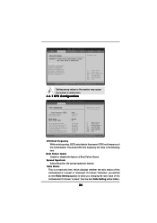
...Select Screen Select Item Change Option General Help Load Defaults Save and Exit Exit v02.54 (C) Copyright 1985-2003, American Megatrends, Inc. 33 Type LBA/Large Mode Block (Multi-Sector Transfer) PIO Mode DMA Mode S.M.A.R.T. 32Bit Data Transfer :Hard Disk :ST340014A :40.0 GB :Supported :16Sectors :4 :MultiWord DMA-2 :Ultra DMA-5 :Supported [Auto] [Auto] [Auto] [Auto] [Auto] [Disabled] [Disabled] Select the type of this item to [Disabled] will use the "Primary IDE Master" as well. 3.3.4 IDE Configuration BIOS SETUP UTILITY Advanced IDE Configuration OnBoard IDE Controller SATA...
...Select Screen Select Item Change Option General Help Load Defaults Save and Exit Exit v02.54 (C) Copyright 1985-2003, American Megatrends, Inc. 33 Type LBA/Large Mode Block (Multi-Sector Transfer) PIO Mode DMA Mode S.M.A.R.T. 32Bit Data Transfer :Hard Disk :ST340014A :40.0 GB :Supported :16Sectors :4 :MultiWord DMA-2 :Ultra DMA-5 :Supported [Auto] [Auto] [Auto] [Auto] [Auto] [Disabled] [Disabled] Select the type of this item to [Disabled] will use the "Primary IDE Master" as well. 3.3.4 IDE Configuration BIOS SETUP UTILITY Advanced IDE Configuration OnBoard IDE Controller SATA...
User Manual
Page 34
... the IDE hard disk data transfer rate. 34 Configuration options: [Not Installed], [Auto], [CD/DVD], and [ARMD]. [Not Installed]: Select [Not Installed] to disable the use a disk utility, such as MO. Block (Multi-Sector Transfer) The default value of this item is enabled, it will enhance hard disk performance by optimizing the hard disk timing. Configuration options: [Disabled], [Auto], [Enabled]. 32-Bit Data Transfer Use this item to enable 32-bit access to enable or disable the S.M.A.R.T. (Self-Monitoring, Analysis, and Reporting Technology) feature...
... the IDE hard disk data transfer rate. 34 Configuration options: [Not Installed], [Auto], [CD/DVD], and [ARMD]. [Not Installed]: Select [Not Installed] to disable the use a disk utility, such as MO. Block (Multi-Sector Transfer) The default value of this item is enabled, it will enhance hard disk performance by optimizing the hard disk timing. Configuration options: [Disabled], [Auto], [Enabled]. 32-Bit Data Transfer Use this item to enable 32-bit access to enable or disable the S.M.A.R.T. (Self-Monitoring, Analysis, and Reporting Technology) feature...
User Manual
Page 35
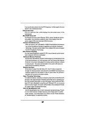
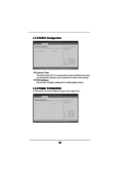
... is recommended to keep the default value unless the installed PCI expansion cards' specifications require other settings. BIOS SETUP UTILITY Advanced Floppy Configuration Floppy A Floppy B [1.44 MB 312"] [Disabled] Select the type of floppy drive connected to enable or disable the PCI IDE BusMaster feature. 3.3.6 Floppy Configuration In this section, you may configure the type of PCI clocks for PCI device latency timer register. +F1 F9 F10 ESC Select Screen Select Item Change Option General Help Load Defaults Save and Exit Exit v02.54 (C) Copyright...
... is recommended to keep the default value unless the installed PCI expansion cards' specifications require other settings. BIOS SETUP UTILITY Advanced Floppy Configuration Floppy A Floppy B [1.44 MB 312"] [Disabled] Select the type of floppy drive connected to enable or disable the PCI IDE BusMaster feature. 3.3.6 Floppy Configuration In this section, you may configure the type of PCI clocks for PCI device latency timer register. +F1 F9 F10 ESC Select Screen Select Item Change Option General Help Load Defaults Save and Exit Exit v02.54 (C) Copyright...
User Manual
Page 36
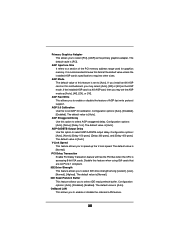
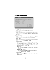
... disable it . Configuration options: [Disabled], [378], and [278]. Configuration options: [IRQ5] and [IRQ7]. 36 Infrared Port Address Use this item to Enable or Disable Floppy Controller. +F1 F9 F10 ESC Select Screen Select Item Change Option General Help Load Defaults Save and Exit Exit v02.54 (C) Copyright 1985-2003, American Megatrends, Inc. 3.3.7 Super IO Configuration BIOS SETUP UTILITY Advanced Configure Super IO Chipset OnBoard Floppy Controller Serial Port Address Infrared Port Address Parallel Port Address Parallel Port Mode EPP Version ECP Mode DMA Channel...
... disable it . Configuration options: [Disabled], [378], and [278]. Configuration options: [IRQ5] and [IRQ7]. 36 Infrared Port Address Use this item to Enable or Disable Floppy Controller. +F1 F9 F10 ESC Select Screen Select Item Change Option General Help Load Defaults Save and Exit Exit v02.54 (C) Copyright 1985-2003, American Megatrends, Inc. 3.3.7 Super IO Configuration BIOS SETUP UTILITY Advanced Configure Super IO Chipset OnBoard Floppy Controller Serial Port Address Infrared Port Address Parallel Port Address Parallel Port Mode EPP Version ECP Mode DMA Channel...
User Manual
Page 37
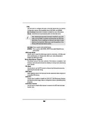
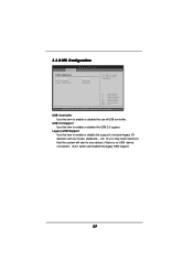
... start to enable or disable the USB 2.0 support. etc. USB Controller Use this item to emulate legacy I/O devices such as mouse, keyboard,... Legacy USB Support Use this item to auto-detect; USB 2.0 Support Use this item to enable or disable the support to enable or disable the use of USB controller. 3.3.8 USB Configuration BIOS SETUP UTILITY Advanced USB Configuration USB Controller USB 2.0 Support Legacy USB Support [Enabled] [Enabled] [Disabled] To enable or disable the onboard USB controllers. +F1 F9 F10 ESC Select Screen Select Item Change Option General Help Load Defaults...
... start to enable or disable the USB 2.0 support. etc. USB Controller Use this item to emulate legacy I/O devices such as mouse, keyboard,... Legacy USB Support Use this item to auto-detect; USB 2.0 Support Use this item to enable or disable the support to enable or disable the use of USB controller. 3.3.8 USB Configuration BIOS SETUP UTILITY Advanced USB Configuration USB Controller USB 2.0 Support Legacy USB Support [Enabled] [Enabled] [Disabled] To enable or disable the onboard USB controllers. +F1 F9 F10 ESC Select Screen Select Item Change Option General Help Load Defaults...

User Manual
Page 40
... Screen Select Item Enter Change F1 General Help F9 Load Defaults F10 Save and Exit ESC Exit v02.54 (C) Copyright 1985-2003, American Megatrends, Inc. Likewise, you may also clear it. For the user password, you may set or change the supervisor/user password for the hard disk drives, the removable drives, and the CD/DVD drives. 40 BIOS SETUP UTILITY Main Advanced H/W Monitor Boot Security Exit Security Settings Supervisor Password : Not Installed User Password : Not Installed Change Supervisor Password Change User Password Install or Change the password. 3.6 Security Screen...
... Screen Select Item Enter Change F1 General Help F9 Load Defaults F10 Save and Exit ESC Exit v02.54 (C) Copyright 1985-2003, American Megatrends, Inc. Likewise, you may also clear it. For the user password, you may set or change the supervisor/user password for the hard disk drives, the removable drives, and the CD/DVD drives. 40 BIOS SETUP UTILITY Main Advanced H/W Monitor Boot Security Exit Security Settings Supervisor Password : Not Installed User Password : Not Installed Change Supervisor Password Change User Password Install or Change the password. 3.6 Security Screen...

User Manual
Page 42
Please install the necessary drivers to activate the devices. 4.2.3 Utilities Menu The Utilities Menu shows the applications software that enhance the motherboard features. 4.2.1 Running The Support CD To begin using the support CD, insert the CD into your computer. Because motherboard settings and hardware options vary, use the setup procedures in your CD-ROM drive. If the Main Menu did not appear automatically, locate and double click on a specific item then follow the installation wizard...
Please install the necessary drivers to activate the devices. 4.2.3 Utilities Menu The Utilities Menu shows the applications software that enhance the motherboard features. 4.2.1 Running The Support CD To begin using the support CD, insert the CD into your computer. Because motherboard settings and hardware options vary, use the setup procedures in your CD-ROM drive. If the Main Menu did not appear automatically, locate and double click on a specific item then follow the installation wizard...


