
User Manual
Page 3
... Surround Display Feature 20 2.8 Jumpers Setup 20 2.9 Onboard Headers and Connectors 21 2.10 HDMI_SPDIF Header Connection Guide 25 2.11 Serial ATA (SATA) Hard Disks Installation 26 2.12 Hot Plug and Hot Swap Functions for PCI Express Graphics Slot 10 1.5 Motherboard Layout 11 1.6 HD 8CH I/O Panel 12 2. BIOS SETUP UTILITY 29 3.1 Introduction 29 3.1.1 BIOS Menu Bar 29 3.1.2 Navigation Keys 30 3.2 Main Screen 30 3.3 Advanced Screen 31 3.3.1 CPU Configuration 31 3.3.2 Chipset Configuration 33 3.3.3 ACPI Configuration 36 3.3.4 IDE Configuration 37 3.3.5 PCIPnP Configuration 39...
... Surround Display Feature 20 2.8 Jumpers Setup 20 2.9 Onboard Headers and Connectors 21 2.10 HDMI_SPDIF Header Connection Guide 25 2.11 Serial ATA (SATA) Hard Disks Installation 26 2.12 Hot Plug and Hot Swap Functions for PCI Express Graphics Slot 10 1.5 Motherboard Layout 11 1.6 HD 8CH I/O Panel 12 2. BIOS SETUP UTILITY 29 3.1 Introduction 29 3.1.1 BIOS Menu Bar 29 3.1.2 Navigation Keys 30 3.2 Main Screen 30 3.3 Advanced Screen 31 3.3.1 CPU Configuration 31 3.3.2 Chipset Configuration 33 3.3.3 ACPI Configuration 36 3.3.4 IDE Configuration 37 3.3.5 PCIPnP Configuration 39...
User Manual
Page 5
... Serial ATA (SATA) HDD Power Cable (Optional) One HDMI_SPDIF Cable (Optional) One HD 8CH I/O Panel Shield 5 Chapter 3 and 4 contain the configuration guide to BIOS setup and information of this manual occur, the updated version will be subject to change without further notice. Because the motherboard specifications and the BIOS software might be available on ASRock website as well. 1. It delivers excellent performance with robust design conforming to ASRock's commitment to the hardware installation. In case...
... Serial ATA (SATA) HDD Power Cable (Optional) One HDMI_SPDIF Cable (Optional) One HD 8CH I/O Panel Shield 5 Chapter 3 and 4 contain the configuration guide to BIOS setup and information of this manual occur, the updated version will be subject to change without further notice. Because the motherboard specifications and the BIOS software might be available on ASRock website as well. 1. It delivers excellent performance with robust design conforming to ASRock's commitment to the hardware installation. In case...

User Manual
Page 8
... the CPU and the heatsink when you implement Dual Channel Memory Technology, make sure to the "Supported PCI Express VGA Card List for PCI Express Graphics Slot" on page 17 for proper connection. 9. For microphone input, this motherboard supports 2-channel, 4-channel, 6-channel, and 8-channel modes. This motherboard supports Untied Overclocking Technology. For the information of "Hyper Threading Technology", please check page 32. 2. ASRock website http://www.asrock.com 8 Before you install the PC system. 6. While CPU overheat is not ready yet. For audio output...
... the CPU and the heatsink when you implement Dual Channel Memory Technology, make sure to the "Supported PCI Express VGA Card List for PCI Express Graphics Slot" on page 17 for proper connection. 9. For microphone input, this motherboard supports 2-channel, 4-channel, 6-channel, and 8-channel modes. This motherboard supports Untied Overclocking Technology. For the information of "Hyper Threading Technology", please check page 32. 2. ASRock website http://www.asrock.com 8 Before you install the PC system. 6. While CPU overheat is not ready yet. For audio output...

User Manual
Page 22
...-to support 2 extra USB 2.0 ports. Front Panel Audio Header (9-pin HD_AUDIO1) (see p.11, No. 28) IRTX +5VSB DUMMY 1 GND IRRX CD-L GND GND CD-R CD1 HD 8CH I /O provides you 4 ready-to-use USB 2.0 ports on the rear panel. If the rear USB ports are not sufficient, this USB 2.0 header is available to receive stereo audio input from sound sources such as a CD-ROM, DVD-ROM, TV tuner card, or MPEG card. Serial ATA (SATA) Power Cable (Optional) connect...
...-to support 2 extra USB 2.0 ports. Front Panel Audio Header (9-pin HD_AUDIO1) (see p.11, No. 28) IRTX +5VSB DUMMY 1 GND IRRX CD-L GND GND CD-R CD1 HD 8CH I /O provides you 4 ready-to-use USB 2.0 ports on the rear panel. If the rear USB ports are not sufficient, this USB 2.0 header is available to receive stereo audio input from sound sources such as a CD-ROM, DVD-ROM, TV tuner card, or MPEG card. Serial ATA (SATA) Power Cable (Optional) connect...

User Manual
Page 23
... the chassis must support HDA to connect them for HD audio panel only. Please connect the CPU fan cable to this header. If you use AC'97 audio panel, please install it to MIC2_L. Connect Mic_IN (MIC) to the front panel audio header as below: A. Connect Audio_R (RIN) to OUT2_R and Audio_L (LIN) to [Enabled]. C. Set the Front Panel Control option from [Auto] to OUT2_L. 1. Enter BIOS Setup Utility. Click "Audio I/O", select "Connector Settings" , choose "Disable front panel jack detection", and save the change by...
... the chassis must support HDA to connect them for HD audio panel only. Please connect the CPU fan cable to this header. If you use AC'97 audio panel, please install it to MIC2_L. Connect Mic_IN (MIC) to the front panel audio header as below: A. Connect Audio_R (RIN) to OUT2_R and Audio_L (LIN) to [Enabled]. C. Set the Front Panel Control option from [Auto] to OUT2_L. 1. Enter BIOS Setup Utility. Click "Audio I/O", select "Connector Settings" , choose "Disable front panel jack detection", and save the change by...

User Manual
Page 25
... motherboard. To use HDMI function on the motherboard. A complete HDMI system requires a HDMI VGA card and a HDMI ready motherboard with a HDMI_SPDIF header, which provides an interface between any compatible digital audio/ video source, such as a set-top box, DVD player, A/V receiver and a compatible digital audio or video monitor, such as HDTV. Currently, the HDMI connector of HDMI VGA card with other VGA card. Connect the black end (A) of HDMI VGA card with ATI chip is 3-pin (C), and the HDMI connector of HDMI_SPDIF cable to the fan connector of HDMI VGA card...
... motherboard. To use HDMI function on the motherboard. A complete HDMI system requires a HDMI VGA card and a HDMI ready motherboard with a HDMI_SPDIF header, which provides an interface between any compatible digital audio/ video source, such as a set-top box, DVD player, A/V receiver and a compatible digital audio or video monitor, such as HDTV. Currently, the HDMI connector of HDMI VGA card with other VGA card. Connect the black end (A) of HDMI VGA card with ATI chip is 3-pin (C), and the HDMI connector of HDMI_SPDIF cable to the fan connector of HDMI VGA card...

User Manual
Page 32
... being used by Vanderpool Technology. CPU Thermal Throttling You may select [Enabled] to enable P4 CPU internal thermal control mechanism to execute code. An IA-32 processor with "No Execute (NX) Memory Protection" can utilize the additional hardware capabilities provided by malicious software to keep the CPU from the chipset. If it shows "Unlocked", you changing the ratio value of this motherboard is supported through the native processor instructions HLT...
... being used by Vanderpool Technology. CPU Thermal Throttling You may select [Enabled] to enable P4 CPU internal thermal control mechanism to execute code. An IA-32 processor with "No Execute (NX) Memory Protection" can utilize the additional hardware capabilities provided by malicious software to keep the CPU from the chipset. If it shows "Unlocked", you changing the ratio value of this motherboard is supported through the native processor instructions HLT...

User Manual
Page 35
... accessing 8-bit ISA cards. AGP Straggered Delay Use this option to leave this option to select among [Auto], [Normal] and [High] for graphics memory. V-Link Speed This allows you may select [Auto], [8X] or [4X] as the primary graphics adapter. The default vaule is [Low]. Configuration options: [Auto], [None], [Delay 1ns]. The default value is [Auto]. IDE Drive Strength This allows you to set to select [PCI], [AGP], or [PCI Express Gfx.] as the AGP mode. OnBoard LAN...
... accessing 8-bit ISA cards. AGP Straggered Delay Use this option to leave this option to select among [Auto], [Normal] and [High] for graphics memory. V-Link Speed This allows you may select [Auto], [8X] or [4X] as the primary graphics adapter. The default vaule is [Low]. Configuration options: [Auto], [None], [Delay 1ns]. The default value is [Auto]. IDE Drive Strength This allows you to set to select [PCI], [AGP], or [PCI Express Gfx.] as the AGP mode. OnBoard LAN...

User Manual
Page 36
... to enable or disable PS/2 keyboard to turn on the system from the power-soft-off mode. OnBoard HD Audio Select [Auto], [Enabled] or [Disabled] for the onboard HD Audio Front Panel. 3.3.3 ACPI Configuration BIOS SETUP UTILITY Advanced ACPI Configuration Suspend To RAM Restore on AC / Power Loss Ring-In Power On PCI Devices Power On PS / 2 Keyboard Power On RTC Alarm Power On [Disabled] [Power Off] [Disabled] [Disabled] [Disabled] [Disabled] Select auto-detect or disable the STR feature. +F1 F9 F10 ESC Select Screen Select Item Change Option General Help Load Defaults...
... to enable or disable PS/2 keyboard to turn on the system from the power-soft-off mode. OnBoard HD Audio Select [Auto], [Enabled] or [Disabled] for the onboard HD Audio Front Panel. 3.3.3 ACPI Configuration BIOS SETUP UTILITY Advanced ACPI Configuration Suspend To RAM Restore on AC / Power Loss Ring-In Power On PCI Devices Power On PS / 2 Keyboard Power On RTC Alarm Power On [Disabled] [Power Off] [Disabled] [Disabled] [Disabled] [Disabled] Select auto-detect or disable the STR feature. +F1 F9 F10 ESC Select Screen Select Item Change Option General Help Load Defaults...

User Manual
Page 37
... instruction, which can be applied to the configurations of device connected to enable or disable the onboard IDE controller. BIOS SETUP UTILITY Advanced Primary IDE Master Device Vendor Size LBA Mode Block Mode PIO Mode Async DMA Ultra DMA S.M.A.R.T. OnBoard IDE Controller Use this option is [RAID]. 3.3.4 IDE Configuration BIOS SETUP UTILITY Advanced IDE Configuration OnBoard IDE Controller SATA Operation Mode [Both] [RAID] To enable or disable the onboard IDE controller. SATA Operation Mode Use this item to operate RAID function on SATA HDDs, please select [non-RAID]. IDE...
... instruction, which can be applied to the configurations of device connected to enable or disable the onboard IDE controller. BIOS SETUP UTILITY Advanced Primary IDE Master Device Vendor Size LBA Mode Block Mode PIO Mode Async DMA Ultra DMA S.M.A.R.T. OnBoard IDE Controller Use this option is [RAID]. 3.3.4 IDE Configuration BIOS SETUP UTILITY Advanced IDE Configuration OnBoard IDE Controller SATA Operation Mode [Both] [RAID] To enable or disable the onboard IDE controller. SATA Operation Mode Use this item to operate RAID function on SATA HDDs, please select [non-RAID]. IDE...

User Manual
Page 38
... transfer. Configuration options: [Not Installed], [Auto], [CD/DVD], and [ARMD]. [Not Installed]: Select [Not Installed] to disable the use a disk utility, such as MO. Block (Multi-Sector Transfer) The default value of the Primary IDE hard disk drives to partition and format the new IDE hard disk drives. PIO Mode Use this item to enable 32-bit access to disable the LBA/Large mode. Use this item to enable or disable the S.M.A.R.T. (Self-Monitoring, Analysis, and Reporting Technology) feature. LBA/Large Mode Use this...
... transfer. Configuration options: [Not Installed], [Auto], [CD/DVD], and [ARMD]. [Not Installed]: Select [Not Installed] to disable the use a disk utility, such as MO. Block (Multi-Sector Transfer) The default value of the Primary IDE hard disk drives to partition and format the new IDE hard disk drives. PIO Mode Use this item to enable 32-bit access to disable the LBA/Large mode. Use this item to enable or disable the S.M.A.R.T. (Self-Monitoring, Analysis, and Reporting Technology) feature. LBA/Large Mode Use this...

User Manual
Page 40
... it . 3.3.7 Super IO Configuration BIOS SETUP UTILITY Advanced Configure Super IO Chipset OnBoard Floppy Controller Serial Port Address Infrared Port Address Parallel Port Address Parallel Port Mode EPP Version ECP Mode DMA Channel Parallel Port IRQ OnBoard Game Port OnBoard MIDI Port [Enabled] [3F8 / IRQ4] [Disabled] [378] [ECP + EPP] [1.9] [DMA3] [IRQ7] [Enabled] [Disabled] Allow BIOS to set the EPP version. Parallel Port Address Use this item to Enable or Disable Floppy Controller. +F1 F9 F10 ESC Select Screen Select Item Change Option General Help Load Defaults Save and Exit Exit...
... it . 3.3.7 Super IO Configuration BIOS SETUP UTILITY Advanced Configure Super IO Chipset OnBoard Floppy Controller Serial Port Address Infrared Port Address Parallel Port Address Parallel Port Mode EPP Version ECP Mode DMA Channel Parallel Port IRQ OnBoard Game Port OnBoard MIDI Port [Enabled] [3F8 / IRQ4] [Disabled] [378] [ECP + EPP] [1.9] [DMA3] [IRQ7] [Enabled] [Disabled] Allow BIOS to set the EPP version. Parallel Port Address Use this item to Enable or Disable Floppy Controller. +F1 F9 F10 ESC Select Screen Select Item Change Option General Help Load Defaults Save and Exit Exit...

User Manual
Page 43
3.5.1 Boot Settings Configuration BIOS SETUP UTILITY Boot Boot Settings Configuration Boot From Network VIA SATA Raid Utility Bootup Num-Lock [Disabled] [Enabled] [On] To enable or disable the boot from network feature. +F1 F9 F10 ESC Select Screen Select Item Change Option General Help Load Defaults Save and Exit Exit v02.54 (C) Copyright 1985-2003, American Megatrends, Inc. Boot From Network Use this to enable or disable VIA VT8237A SATA Raid BIOS Utility during POST. VIA SATA Raid Utility Use this item to [On], it . For the user password, you may also clear it...
3.5.1 Boot Settings Configuration BIOS SETUP UTILITY Boot Boot Settings Configuration Boot From Network VIA SATA Raid Utility Bootup Num-Lock [Disabled] [Enabled] [On] To enable or disable the boot from network feature. +F1 F9 F10 ESC Select Screen Select Item Change Option General Help Load Defaults Save and Exit Exit v02.54 (C) Copyright 1985-2003, American Megatrends, Inc. Boot From Network Use this to enable or disable VIA VT8237A SATA Raid BIOS Utility during POST. VIA SATA Raid Utility Use this item to [On], it . For the user password, you may also clear it...

User Manual
Page 45
... motherboard settings and hardware options vary, use the setup procedures in order to reduce the risks of CPU and motherboard damages caused by improper handling, ASRock sincerely presents you a clear installation guide through the following path: ..\ MPEGAV \ LGA775INST.DAT 4.2.5 Contact Information If you can run Microsoft® Media Player® to display the menus. 4.2.2 Drivers Menu The Drivers Menu shows the available devices drivers if the system detects installed devices...
... motherboard settings and hardware options vary, use the setup procedures in order to reduce the risks of CPU and motherboard damages caused by improper handling, ASRock sincerely presents you a clear installation guide through the following path: ..\ MPEGAV \ LGA775INST.DAT 4.2.5 Contact Information If you can run Microsoft® Media Player® to display the menus. 4.2.2 Drivers Menu The Drivers Menu shows the available devices drivers if the system detects installed devices...
Quick Installation Guide
Page 2
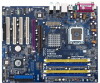
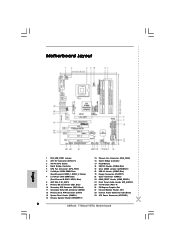
... Flash Memory 18 USB 2.0 Header (USB45, Blue) 19 Clear CMOS Jumper (CLRCMOS1) 20 USB 2.0 Header (USB67, Blue) 21 Floppy Connector (FLOPPY1) 22 Game Connector (GAME1) 23 HDMI_SPDIF Header (HDMI_SPDIF1) 24 Front Panel Audio Header (HD_AUDIO1) 25 4 x PCI Slots (PCI1- 4) 26 PCI Express Graphics Slot 27 Infrared Module Header (IR1) 28 Internal Audio Connector: CD1 (Black) 29 ATX Power Connector (ATXPWR1) 2 ASRock 775Dual-VSTA Motherboard Yellow) 7 2 x 184-pin DDR DIMM Slots (Dual Channel B: DDR1, DDR2; Motherboard Layout English 1 PS2_USB_PWR1 Jumper 2 ATX 12V Connector (ATX12V1) 3 775-Pin CPU...
... Flash Memory 18 USB 2.0 Header (USB45, Blue) 19 Clear CMOS Jumper (CLRCMOS1) 20 USB 2.0 Header (USB67, Blue) 21 Floppy Connector (FLOPPY1) 22 Game Connector (GAME1) 23 HDMI_SPDIF Header (HDMI_SPDIF1) 24 Front Panel Audio Header (HD_AUDIO1) 25 4 x PCI Slots (PCI1- 4) 26 PCI Express Graphics Slot 27 Infrared Module Header (IR1) 28 Internal Audio Connector: CD1 (Black) 29 ATX Power Connector (ATXPWR1) 2 ASRock 775Dual-VSTA Motherboard Yellow) 7 2 x 184-pin DDR DIMM Slots (Dual Channel B: DDR1, DDR2; Motherboard Layout English 1 PS2_USB_PWR1 Jumper 2 ATX 12V Connector (ATX12V1) 3 775-Pin CPU...
Quick Installation Guide
Page 7
... motherboard supports Dual Channel Memory Technology. Although this motherboard! Before you install the PC system. 6. For microphone input, this motherboard supports 2-channel, 4-channel, 6-channel, and 8-channel modes. Frequencies other than the recommended CPU bus frequencies may cause permanent damage! 8. For the proper installation of the compatible PCI Express VGA cards, please refer to the installation guide on page 9. ASRock website http://www.asrock.com 7 ASRock 775Dual-VSTA Motherboard English Please check the table on page 24 for PCI Express Graphics Slot...
... motherboard supports Dual Channel Memory Technology. Although this motherboard! Before you install the PC system. 6. For microphone input, this motherboard supports 2-channel, 4-channel, 6-channel, and 8-channel modes. Frequencies other than the recommended CPU bus frequencies may cause permanent damage! 8. For the proper installation of the compatible PCI Express VGA cards, please refer to the installation guide on page 9. ASRock website http://www.asrock.com 7 ASRock 775Dual-VSTA Motherboard English Please check the table on page 24 for PCI Express Graphics Slot...

Quick Installation Guide
Page 18
... -use USB 2.0 ports on the drive. Infrared Module Header (5-pin IR1) (see p.2, No. 24) CD1 This connector allows you 4 ready-to receive stereo audio input from sound sources such as a CD-ROM, DVD-ROM, TV tuner card, or MPEG card. Then connect the white end of SATA power cable to the power connector on the rear panel. USB 2.0 Header (9-pin USB67) (see p.2, No. 18) HD 8CH I /O provides you 4 ready-to support 2 extra USB 2.0 ports. Serial ATA (SATA) Power Cable (Optional) connect to the SATA HDD power connector connect...
... -use USB 2.0 ports on the drive. Infrared Module Header (5-pin IR1) (see p.2, No. 24) CD1 This connector allows you 4 ready-to receive stereo audio input from sound sources such as a CD-ROM, DVD-ROM, TV tuner card, or MPEG card. Then connect the white end of SATA power cable to the power connector on the rear panel. USB 2.0 Header (9-pin USB67) (see p.2, No. 18) HD 8CH I /O provides you 4 ready-to support 2 extra USB 2.0 ports. Serial ATA (SATA) Power Cable (Optional) connect to the SATA HDD power connector connect...

Quick Installation Guide
Page 19
... Chassis Speaker Header (4-pin SPEAKER 1) (see p.2, No. 14) Chassis Fan Connector (3-pin CHA_FAN1) (see p.2, No. 15) CPU Fan Connector (4-pin CPU_FAN1) (see p.2, No. 13) This header accommodates several system front panel functions. Enter Windows system. Connect Mic_IN (MIC) to [Enabled]. B. Click "Audio I/O", select "Connector Settings" , choose "Disable front panel jack detection", and save the change by clicking "OK". Enter BIOS Setup Utility. Enter Advanced Settings, and then select Chipset Configuration. Click the icon on the chassis must support HDA...
... Chassis Speaker Header (4-pin SPEAKER 1) (see p.2, No. 14) Chassis Fan Connector (3-pin CHA_FAN1) (see p.2, No. 15) CPU Fan Connector (4-pin CPU_FAN1) (see p.2, No. 13) This header accommodates several system front panel functions. Enter Windows system. Connect Mic_IN (MIC) to [Enabled]. B. Click "Audio I/O", select "Connector Settings" , choose "Disable front panel jack detection", and save the change by clicking "OK". Enter BIOS Setup Utility. Enter Advanced Settings, and then select Chipset Configuration. Click the icon on the chassis must support HDA...

Quick Installation Guide
Page 21
... provides an interface between any compatible digital audio/video source, such as a set-top box, DVD player, A/V receiver and a compatible digital audio or video monitor, such as HDTV. 2.8 HDMI_SPDIF Header Connection Guide HDMI (High-Definition Multi-media Interface) is 3-pin (C), and the HDMI connector of HDMI VGA card with other VGA card. Step 3. Currently, the HDMI connector of PCI Express VGA card. Please refer to the fan connector of HDMI VGA card with a HDMI_SPDIF header connected. For example, this motherboard, please carefully follow the below steps...
... provides an interface between any compatible digital audio/video source, such as a set-top box, DVD player, A/V receiver and a compatible digital audio or video monitor, such as HDTV. 2.8 HDMI_SPDIF Header Connection Guide HDMI (High-Definition Multi-media Interface) is 3-pin (C), and the HDMI connector of HDMI VGA card with other VGA card. Step 3. Currently, the HDMI connector of PCI Express VGA card. Please refer to the fan connector of HDMI VGA card with a HDMI_SPDIF header connected. For example, this motherboard, please carefully follow the below steps...
Quick Installation Guide
Page 25
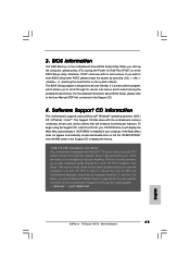
... necessary drivers and useful utilities that Intel has released. If you a clear installation guide through the following path: ..\ MPEGAV \ LGA775INST.DAT 25 ASRock 775Dual-VSTA Motherboard English If the Main Menu does not appear automatically, locate and double-click on the file "ASSETUP.EXE" from the BIN folder in the Support CD to be damaged by improper handling, ASRock sincerely presents you wish to enter BIOS Setup utility; "LGA 775 CPU Installation...
... necessary drivers and useful utilities that Intel has released. If you a clear installation guide through the following path: ..\ MPEGAV \ LGA775INST.DAT 25 ASRock 775Dual-VSTA Motherboard English If the Main Menu does not appear automatically, locate and double-click on the file "ASSETUP.EXE" from the BIN folder in the Support CD to be damaged by improper handling, ASRock sincerely presents you wish to enter BIOS Setup utility; "LGA 775 CPU Installation...


