
User Manual
Page 3
... Layout 10 1.5 HD 8CH I/O 11 2 Installation 12 2.1 Screw Holes 12 2.2 Pre-installation Precautions 12 2.3 CPU Installation 13 2.4 Installation of Heatsink and CPU fan 15 2.5 Installation of Memory Modules (DIMM 16 2.6 Expansion Slots (PCI, HDMR, and PCI Express Slots)...SETUP UTILITY 28 3.1 Introduction 28 3.1.1 BIOS Menu Bar 28 3.1.2 Navigation Keys 29 3.2 Main Screen 29 3.3 Advanced Screen 29 3.3.1 CPU Configuration 30 3.3.2 Chipset Configuration 32 3.3.3 ACPI Configuration 35 3.3.4 IDE Configuration 36 3.3.5 PCIPnP Configuration 38 3.3.6 Floppy Configuration 39 3.3.7 Super...
... Layout 10 1.5 HD 8CH I/O 11 2 Installation 12 2.1 Screw Holes 12 2.2 Pre-installation Precautions 12 2.3 CPU Installation 13 2.4 Installation of Heatsink and CPU fan 15 2.5 Installation of Memory Modules (DIMM 16 2.6 Expansion Slots (PCI, HDMR, and PCI Express Slots)...SETUP UTILITY 28 3.1 Introduction 28 3.1.1 BIOS Menu Bar 28 3.1.2 Navigation Keys 29 3.2 Main Screen 29 3.3 Advanced Screen 29 3.3.1 CPU Configuration 30 3.3.2 Chipset Configuration 32 3.3.3 ACPI Configuration 35 3.3.4 IDE Configuration 36 3.3.5 PCIPnP Configuration 38 3.3.6 Floppy Configuration 39 3.3.7 Super...

User Manual
Page 5
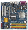
... latest VGA cards and CPU support lists on ASRock website without notice. ASRock website http://www.asrock.com 1.1 Package Contents ASRock 2Core1333DVI-2.66G Motherboard Bundled With Selected Dual Core CPU Operating at FSB1333 / 2.66GHz (Micro ATX Form Factor: 9.6-in x 9.6-in, 24.4 cm x 24.4 cm) One selected Dual Core CPU operating at FSB1333 / 2.66GHz ASRock 2Core1333DVI-2.66G Quick Installation Guide ASRock 2Core1333DVI-2.66G Support CD One...
... latest VGA cards and CPU support lists on ASRock website without notice. ASRock website http://www.asrock.com 1.1 Package Contents ASRock 2Core1333DVI-2.66G Motherboard Bundled With Selected Dual Core CPU Operating at FSB1333 / 2.66GHz (Micro ATX Form Factor: 9.6-in x 9.6-in, 24.4 cm x 24.4 cm) One selected Dual Core CPU operating at FSB1333 / 2.66GHz ASRock 2Core1333DVI-2.66G Quick Installation Guide ASRock 2Core1333DVI-2.66G Support CD One...

User Manual
Page 6
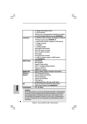
...ASRock U-COP (see CAUTION 4) - Intel® Graphics Media Accelerator 950 - Realtek RTL8111B - Supports Wake-On-LAN Rear Panel I/O HD 8CH I/O - 1 x PS/2 Mouse Port - 1 x PS/2 Keyboard Port - 1 x VGA Port - 1 x Parallel Port (ECP/EPP Support) 6 Compatible with selected Dual Core CPU...shared memory 224MB (see CAUTION 1) - Supports HDCP function with DVI Graphics-HDCP card by independent display controllers - 1.2 Specifications Platform - CPU Frequency Stepless Control (see CAUTION 2) - Boot Failure Guard (B.F.G.) Expansion Slot - 1 x PCI Express x16 slot - 1 x PCI ...
...ASRock U-COP (see CAUTION 4) - Intel® Graphics Media Accelerator 950 - Realtek RTL8111B - Supports Wake-On-LAN Rear Panel I/O HD 8CH I/O - 1 x PS/2 Mouse Port - 1 x PS/2 Keyboard Port - 1 x VGA Port - 1 x Parallel Port (ECP/EPP Support) 6 Compatible with selected Dual Core CPU...shared memory 224MB (see CAUTION 1) - Supports HDCP function with DVI Graphics-HDCP card by independent display controllers - 1.2 Specifications Platform - CPU Frequency Stepless Control (see CAUTION 2) - Boot Failure Guard (B.F.G.) Expansion Slot - 1 x PCI Express x16 slot - 1 x PCI ...

User Manual
Page 7
...10) - 4 x SATAII 3.0 Gb/s connectors (No Support for possible damage caused by overclocking. 7 CPU/Chassis FAN connector - 20 pin ATX power connector - 4 pin 12V power connector - Supports "Plug and Play" - CPU Quiet Fan - Front panel audio connector - 2 x USB 2.0 headers (support 4 USB 2.0 ports)... 11) - 1 x ATA100 IDE connector (supports 2 x IDE devices) - 1 x Floppy connector - 1 x IR header - 1 x COM port header - CPU Fan Tachometer - Chassis Fan Tachometer - Voltage Monitoring: +12V, +5V, +3.3V, Vcore - FCC, CE, WHQL WARNING Please realize that there is a certain risk ...
...10) - 4 x SATAII 3.0 Gb/s connectors (No Support for possible damage caused by overclocking. 7 CPU/Chassis FAN connector - 20 pin ATX power connector - 4 pin 12V power connector - Supports "Plug and Play" - CPU Quiet Fan - Front panel audio connector - 2 x USB 2.0 headers (support 4 USB 2.0 ports)... 11) - 1 x ATA100 IDE connector (supports 2 x IDE devices) - 1 x Floppy connector - 1 x IR header - 1 x COM port header - CPU Fan Tachometer - Chassis Fan Tachometer - Voltage Monitoring: +12V, +5V, +3.3V, Vcore - FCC, CE, WHQL WARNING Please realize that there is a certain risk ...

User Manual
Page 8
... Untied Overclocking Technology. There are memory module installation limitations on this motherboard supports 2-channel, 4-channel, 6-channel, and 8-channel modes. CPU FSB Frequency Memory Support Frequency 1333 DDRII533*, DDRII667 1066 DDRII533, DDRII667 800 DDRII400, DDRII533, DDRII667 533 DDRII400, DDRII533 * When you ... to the chipset limitation, the actual memory size may cause the instability of the system or damage the CPU. 8. Under this motherboard supports both stereo and mono modes. This motherboard supports Dual Channel Memory Technology. Frequencies...
... Untied Overclocking Technology. There are memory module installation limitations on this motherboard supports 2-channel, 4-channel, 6-channel, and 8-channel modes. CPU FSB Frequency Memory Support Frequency 1333 DDRII533*, DDRII667 1066 DDRII533, DDRII667 800 DDRII400, DDRII533, DDRII667 533 DDRII400, DDRII533 * When you ... to the chipset limitation, the actual memory size may cause the instability of the system or damage the CPU. 8. Under this motherboard supports both stereo and mono modes. This motherboard supports Dual Channel Memory Technology. Frequencies...

User Manual
Page 10
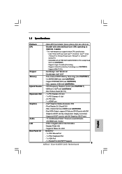
...26 25 24 23 Top: LINE IN Center: FRONT Bottom: MIC IN Top: SIDE SPK Center: REAR SPK Bottom: CTR BASS COM1 1 Dual Core CPU Dual Channel USB 2.0 T: USB2 B: USB3 USB 2.0 T: USB0 B: USB1 Top: RJ-45 Super IO 4Mb BIOS ATXPWR1 HDCP PCI EXPRESS PCIE1 Intel 945GC...1CH HD HDMR1 FLOPPY1 Intel ICH7 SATAII 1 USB4_5 IDE1 1 USB6_7 SATAII_3 SATAII_1 USB2.0 CHA_FAN1 SATAII_4 SATAII_2 SPEAKER1 1 PANEL 1 PLED PWRBTN 1 HDLED RESET 2Core1333DVI-2.66G 22 21 20 19 18 17 161514 13 DDRII667 24.4cm (9.6 in) 9 10 11 12 1 PS2_USB_PWR1 Jumper 15 Third SATAII Connector (SATAII_3; Red...
...26 25 24 23 Top: LINE IN Center: FRONT Bottom: MIC IN Top: SIDE SPK Center: REAR SPK Bottom: CTR BASS COM1 1 Dual Core CPU Dual Channel USB 2.0 T: USB2 B: USB3 USB 2.0 T: USB0 B: USB1 Top: RJ-45 Super IO 4Mb BIOS ATXPWR1 HDCP PCI EXPRESS PCIE1 Intel 945GC...1CH HD HDMR1 FLOPPY1 Intel ICH7 SATAII 1 USB4_5 IDE1 1 USB6_7 SATAII_3 SATAII_1 USB2.0 CHA_FAN1 SATAII_4 SATAII_2 SPEAKER1 1 PANEL 1 PLED PWRBTN 1 HDLED RESET 2Core1333DVI-2.66G 22 21 20 19 18 17 161514 13 DDRII667 24.4cm (9.6 in) 9 10 11 12 1 PS2_USB_PWR1 Jumper 15 Third SATAII Connector (SATAII_3; Red...
User Manual
Page 13
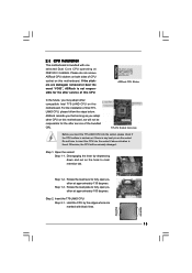
...approximately 135 degrees. Step 1-3. black line black line 13 Step 1. Step 2. ASRock CPU Sticker In the future, you may adopt other CPU on this CPU. For the installation of CPU socket on the socket. Otherwise, the CPU will not be seriously damaged. Open the socket: Step 1-1. Step 1-2. Rotate ...the load plate to insert the CPU into the socket, please check if the CPU surface is unclean or if there is any bent pin on this motherboard. 2.3 CPU Installation This motherboard is bundled with black lines. ASRock reminds you that as long as you insert ...
...approximately 135 degrees. Step 1-3. black line black line 13 Step 1. Step 2. ASRock CPU Sticker In the future, you may adopt other CPU on this CPU. For the installation of CPU socket on the socket. Otherwise, the CPU will not be seriously damaged. Open the socket: Step 1-1. Step 1-2. Rotate ...the load plate to insert the CPU into the socket, please check if the CPU surface is unclean or if there is any bent pin on this motherboard. 2.3 CPU Installation This motherboard is bundled with black lines. ASRock reminds you that as long as you insert ...

User Manual
Page 14
... PnP cap with the two alignment keys of the socket. Step 2-2. Pin1 orientation key notch orientation key notch Pin1 alignment key alignment key 775-LAND CPU 775-Pin Socket For proper inserting, please ensure to assist in removal. 1. Step 2-3. Secure load lever with IHS (Integrated Heat Sink) up. Step 4. Orient the... load plate tab under retention tab of PnP cap to match the two orientation key notches of the CPU with right hand thumb and peel the cap from the socket while pressing on load plate, engage the load lever. It is within the socket ...
... PnP cap with the two alignment keys of the socket. Step 2-2. Pin1 orientation key notch orientation key notch Pin1 alignment key alignment key 775-LAND CPU 775-Pin Socket For proper inserting, please ensure to assist in removal. 1. Step 2-3. Secure load lever with IHS (Integrated Heat Sink) up. Step 4. Orient the... load plate tab under retention tab of PnP cap to match the two orientation key notches of the CPU with right hand thumb and peel the cap from the socket while pressing on load plate, engage the load lever. It is within the socket ...

User Manual
Page 15
... with fan operation or contact other . Before you installed the heatsink, you press down on the socket surface. Then connect the CPU fan to ensure cable does not interfere with remaining fasteners. Step 6. Step 4. Secure excess cable with tie-wrap to the CPU_FAN connector... of IHS on fastener caps with each other components. 15 Ensure fan cables are securely fastened and in good contact with thumb to the CPU fan connector on the motherboard (CPU_FAN1, see page 10, No. 3). Rotate the fastener clockwise, then press down the fasteners without rotating them...
... with fan operation or contact other . Before you installed the heatsink, you press down on the socket surface. Then connect the CPU fan to ensure cable does not interfere with remaining fasteners. Step 6. Step 4. Secure excess cable with tie-wrap to the CPU_FAN connector... of IHS on fastener caps with each other components. 15 Ensure fan cables are securely fastened and in good contact with thumb to the CPU fan connector on the motherboard (CPU_FAN1, see page 10, No. 3). Rotate the fastener clockwise, then press down the fasteners without rotating them...

User Manual
Page 24
...1-3 Connected 3-Pin Fan Installation ATX Power Connector (20-pin ATXPWR1) (see p.10 No. 3) +12V CPU_FAN_SPEED GND FAN_SPEED_CONTROL 1 2 3 4 Please connect a CPU fan cable to this connector. Click "Audio I/O", select "Connector Settings" , choose "Disable front panel jack detection", and save the change by clicking "OK". ... this connector and match the black wire to enter Realtek HD Audio Manager. F. If you plan to connect the 3-Pin CPU fan to the CPU fan connector on the lower right hand taskbar to the ground pin. System Panel Header (9-pin PANEL1) (see p.10 No...
...1-3 Connected 3-Pin Fan Installation ATX Power Connector (20-pin ATXPWR1) (see p.10 No. 3) +12V CPU_FAN_SPEED GND FAN_SPEED_CONTROL 1 2 3 4 Please connect a CPU fan cable to this connector. Click "Audio I/O", select "Connector Settings" , choose "Disable front panel jack detection", and save the change by clicking "OK". ... this connector and match the black wire to enter Realtek HD Audio Manager. F. If you plan to connect the 3-Pin CPU fan to the CPU fan connector on the lower right hand taskbar to the ground pin. System Panel Header (9-pin PANEL1) (see p.10 No...

User Manual
Page 27
...can operate under a more stable overclocking environment. Install HDMR card driver from our support CD to install the SATA / SATAII hard disks. Therefore, CPU FSB is completely seated on this motherboard, and you to your system now, but PCI / PCIE buses are in the future, you apply ...to the SATA / SATAII hard disk. 2.12 Driver Installation Guide To install the drivers to your system, please insert the support CD to [CPU, PCIE, Async.]. This section will guide you finish installing all drivers to the motherboard's SATAII connector. Before you install can be auto-detected ...
...can operate under a more stable overclocking environment. Install HDMR card driver from our support CD to install the SATA / SATAII hard disks. Therefore, CPU FSB is completely seated on this motherboard, and you to your system now, but PCI / PCIE buses are in the future, you apply ...to the SATA / SATAII hard disk. 2.12 Driver Installation Guide To install the drivers to your system, please insert the support CD to [CPU, PCIE, Async.]. This section will guide you finish installing all drivers to the motherboard's SATAII connector. Before you install can be auto-detected ...

User Manual
Page 29
...UTILITY H/W Monitor Boot System Overview System Time System Date [14:00:09] [Fri 07/06/2007] BIOS Version : 2Core1333DVI-2.66G L0.02 Processor Type : Dual Core CPU operating at FSB1333/2.66GHz (64bit) Processor Speed : 2666MHz Microcode Update : 6FD/A1 Cache Size : 1024KB Total Memory ...table for the function description of each navigation key. 3.1.2 Navigation Keys Please check the following items: CPU Configuration, Chipset Configuration, ACPI Configuration, IDE Configuration, PCIPnP Configuration, Floppy Configuration, SuperIO Configuration, and USB Configuration. 29
...UTILITY H/W Monitor Boot System Overview System Time System Date [14:00:09] [Fri 07/06/2007] BIOS Version : 2Core1333DVI-2.66G L0.02 Processor Type : Dual Core CPU operating at FSB1333/2.66GHz (64bit) Processor Speed : 2666MHz Microcode Update : 6FD/A1 Cache Size : 1024KB Total Memory ...table for the function description of each navigation key. 3.1.2 Navigation Keys Please check the following items: CPU Configuration, Chipset Configuration, ACPI Configuration, IDE Configuration, PCIPnP Configuration, Floppy Configuration, SuperIO Configuration, and USB Configuration. 29

User Manual
Page 30
...Save and Exit Exit v02.54 (C) Copyright 1985-2005, American Megatrends, Inc. Overclock Mode Use this to adjust CPU frequency. CPU Frequency (MHz) Use this option to select Overclock Mode. Spread Spectrum This item should always be [Auto] for better system... stability. 30 CPU Configuration Chipset Configuration ACPI Configuration IDE Configuration PCIPnP Configuration Floppy Configuration SuperIO Configuration USB Configuration Configure CPU Select Screen Select Item Enter Go to adjust PCIE frequency. The default value ...
...Save and Exit Exit v02.54 (C) Copyright 1985-2005, American Megatrends, Inc. Overclock Mode Use this to adjust CPU frequency. CPU Frequency (MHz) Use this option to select Overclock Mode. Spread Spectrum This item should always be [Auto] for better system... stability. 30 CPU Configuration Chipset Configuration ACPI Configuration IDE Configuration PCIPnP Configuration Floppy Configuration SuperIO Configuration USB Configuration Configure CPU Select Screen Select Item Enter Go to adjust PCIE frequency. The default value ...

User Manual
Page 31
.... NT4.0) cannot handle the function with "No Execute (NX) Memory Protection" can switch between multiple frequency and voltage points to keep the CPU from being used by Vanderpool Technology. Hyper Threading Technology To enable this technology, such as "Portable/Laptop" to [Enabled]. An IA-32... processor with disable. Processor can prevent data pages from overheated. This should be hidden if the current CPU does not support No-Excute Memory Protection. is an enhancement to [Enabled] if using Microsoft® Windows® XP, or Linux kernel...
.... NT4.0) cannot handle the function with "No Execute (NX) Memory Protection" can switch between multiple frequency and voltage points to keep the CPU from being used by Vanderpool Technology. Hyper Threading Technology To enable this technology, such as "Portable/Laptop" to [Enabled]. An IA-32... processor with disable. Processor can prevent data pages from overheated. This should be hidden if the current CPU does not support No-Excute Memory Protection. is an enhancement to [Enabled] if using Microsoft® Windows® XP, or Linux kernel...

User Manual
Page 32
You may reduce CPU voltage and lead to system stability or compatibility issue with some power supplies. Configuration options are [6], [5], [4], [3], and [Auto]. Please set to the corresponding FSB frequency ... item to CAS# Delay This controls the latency between the DRAM active command and the read / write command. Flexibility Option The default value of the CPU you adjusting them. The configuration options may change according to [Enabled]. It will find the items "DRAM RAS# to CAS# Delay", "DRAM RAS# Precharge", and...
You may reduce CPU voltage and lead to system stability or compatibility issue with some power supplies. Configuration options are [6], [5], [4], [3], and [Auto]. Please set to the corresponding FSB frequency ... item to CAS# Delay This controls the latency between the DRAM active command and the read / write command. Flexibility Option The default value of the CPU you adjusting them. The configuration options may change according to [Enabled]. It will find the items "DRAM RAS# to CAS# Delay", "DRAM RAS# Precharge", and...

User Manual
Page 41
...this option to allow you will be between 45 C and 65 C. Tolerance ( C) The default value of the CPU temperature, motherboard temperature, CPU fan speed, chassis fan speed, and the critical voltage. BIOS SETUP UTILITY Main Advanced H/W Monitor Boot Security Exit ...Hardware Health Event Monitoring CPU Temperature M / B Temperature : 37 C / 98 F : 31 C / 87 F Target Fan Speed Fast Middle Slow CPU Fan Speed Chassis Fan Speed : 3400 RPM : N/A Vcore + 3.30V + 5.00V + 12.00V :...
...this option to allow you will be between 45 C and 65 C. Tolerance ( C) The default value of the CPU temperature, motherboard temperature, CPU fan speed, chassis fan speed, and the critical voltage. BIOS SETUP UTILITY Main Advanced H/W Monitor Boot Security Exit ...Hardware Health Event Monitoring CPU Temperature M / B Temperature : 37 C / 98 F : 31 C / 87 F Target Fan Speed Fast Middle Slow CPU Fan Speed Chassis Fan Speed : 3400 RPM : N/A Vcore + 3.30V + 5.00V + 12.00V :...

Quick Installation Guide
Page 2
... B: DDRII_2, DDRII_4; Orange) 29 Serial Port Connector (COM1) 14 Secondary SATAII Connector (SATAII_2; Red) 30 Infrared Module Header (IR1) 2 ASRock 2Core1333DVI-2.66G Motherboard Red) 3 CPU Fan Connector (CPU_FAN1) 17 Chassis Fan Connector (CHA_FAN1) 4 775-Pin CPU Socket 18 USB 2.0 Header (USB6_7, Blue) 5 North Bridge Controller 19 USB 2.0 Header (USB4_5, Blue) 6 Clear CMOS Jumper (CLRCMOS1) 20...
... B: DDRII_2, DDRII_4; Orange) 29 Serial Port Connector (COM1) 14 Secondary SATAII Connector (SATAII_2; Red) 30 Infrared Module Header (IR1) 2 ASRock 2Core1333DVI-2.66G Motherboard Red) 3 CPU Fan Connector (CPU_FAN1) 17 Chassis Fan Connector (CHA_FAN1) 4 775-Pin CPU Socket 18 USB 2.0 Header (USB6_7, Blue) 5 North Bridge Controller 19 USB 2.0 Header (USB4_5, Blue) 6 Clear CMOS Jumper (CLRCMOS1) 20...

Quick Installation Guide
Page 4
... (Optional) One HD 8CH I/O Shield One COM Port Bracket One DVI Graphics-HDCP Card 4 ASRock 2Core1333DVI-2.66G Motherboard English Introduction Thank you for a 3.5-in , 24.4 cm x 24.4 cm) One selected Dual Core CPU operating at FSB1333 / 2.66GHz ASRock 2Core1333DVI-2.66G Quick Installation Guide ASRock 2Core1333DVI-2.66G Support CD One 80-conductor Ultra ATA 66/100 IDE Ribbon Cable One Ribbon...
... (Optional) One HD 8CH I/O Shield One COM Port Bracket One DVI Graphics-HDCP Card 4 ASRock 2Core1333DVI-2.66G Motherboard English Introduction Thank you for a 3.5-in , 24.4 cm x 24.4 cm) One selected Dual Core CPU operating at FSB1333 / 2.66GHz ASRock 2Core1333DVI-2.66G Quick Installation Guide ASRock 2Core1333DVI-2.66G Support CD One 80-conductor Ultra ATA 66/100 IDE Ribbon Cable One Ribbon...
Quick Installation Guide
Page 5
... 10/100/1000 Mb/s - 1.2 Specifications Platform - Supports Hyper-Threading Technology - ASRock U-COP (see CAUTION 9) - shared memory 224MB (see CAUTION 8) - Supports EM64T CPU Chipset - Intel® Graphics Media Accelerator 950 - Supports Untied Overclocking Technology (see...CPU - Dual Channel DDRII Memory Technology (see CAUTION 3) - 4 x DDRII DIMM slots (see CAUTION 1) - Supports Wake-On-LAN Rear Panel I/O HD 8CH I/O - 1 x PS/2 Mouse Port - 1 x PS/2 Keyboard Port - 1 x VGA Port - 1 x Parallel Port (ECP/EPP Support) 5 ASRock 2Core1333DVI-2.66G...
... 10/100/1000 Mb/s - 1.2 Specifications Platform - Supports Hyper-Threading Technology - ASRock U-COP (see CAUTION 9) - shared memory 224MB (see CAUTION 8) - Supports EM64T CPU Chipset - Intel® Graphics Media Accelerator 950 - Supports Untied Overclocking Technology (see...CPU - Dual Channel DDRII Memory Technology (see CAUTION 3) - 4 x DDRII DIMM slots (see CAUTION 1) - Supports Wake-On-LAN Rear Panel I/O HD 8CH I/O - 1 x PS/2 Mouse Port - 1 x PS/2 Keyboard Port - 1 x VGA Port - 1 x Parallel Port (ECP/EPP Support) 5 ASRock 2Core1333DVI-2.66G...
Quick Installation Guide
Page 6
...) (see CAUTION 10) - 4 x SATAII 3.0 Gb/s connectors (No Support for possible damage caused by overclocking. 6 ASRock 2Core1333DVI-2.66G Motherboard AMI Legal BIOS - Connector BIOS Feature Support CD Hardware Monitor OS Certifications - 4 x Ready-to the components and devices of your system. CPU/Chassis FAN connector - 20 pin ATX power connector - 4 pin 12V power connector - Chassis Temperature...
...) (see CAUTION 10) - 4 x SATAII 3.0 Gb/s connectors (No Support for possible damage caused by overclocking. 6 ASRock 2Core1333DVI-2.66G Motherboard AMI Legal BIOS - Connector BIOS Feature Support CD Hardware Monitor OS Certifications - 4 x Ready-to the components and devices of your system. CPU/Chassis FAN connector - 20 pin ATX power connector - 4 pin 12V power connector - Chassis Temperature...


