User Manual
Page 3
... Slots (PCI, HDMR, and PCI Express Slots) ....... 17 2.7 Jumpers Setup 18 2.8 Onboard Headers and Connectors 19 2.9 SATAII Hard Disk Setup Guide 23 2.10 Serial ATA (SATA) / Serial ATAII (SATAII) Hard Disks Installation 24 2.11 Driver Installation Guide 24 2.12 HDMR Card and Driver Installation 24 2.13 Untied Overclocking Technology 24 3 BIOS SETUP UTILITY 25 3.1 Introduction 25 3.1.1 BIOS Menu Bar 25 3.1.2 Navigation Keys 26 3.2 Main Screen 26 3.3 Advanced Screen 26 3.3.1 CPU Configuration 27 3.3.2 Chipset Configuration 29 3.3.3 ACPI Configuration 32 3.3.4 IDE Configuration...
... Slots (PCI, HDMR, and PCI Express Slots) ....... 17 2.7 Jumpers Setup 18 2.8 Onboard Headers and Connectors 19 2.9 SATAII Hard Disk Setup Guide 23 2.10 Serial ATA (SATA) / Serial ATAII (SATAII) Hard Disks Installation 24 2.11 Driver Installation Guide 24 2.12 HDMR Card and Driver Installation 24 2.13 Untied Overclocking Technology 24 3 BIOS SETUP UTILITY 25 3.1 Introduction 25 3.1.1 BIOS Menu Bar 25 3.1.2 Navigation Keys 26 3.2 Main Screen 26 3.3 Advanced Screen 26 3.3.1 CPU Configuration 27 3.3.2 Chipset Configuration 29 3.3.3 ACPI Configuration 32 3.3.4 IDE Configuration...
User Manual
Page 7
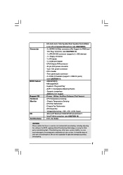
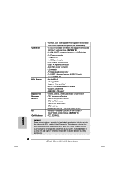
...; 2000/XP/XP 64-bit/VistaTM/ VistaTM 64-bit compliant (see CAUTION 11) - 4Mb AMI BIOS - AMBIOS 2.3.1 Support - CPU Temperature Sensing - Chassis Temperature Sensing - FCC, CE, WHQL WARNING Please realize that there is a certain risk involved with overclocking, including adjusting the setting in header - CPU/Chassis FAN connector - 20 pin ATX power connector - 4 pin 12V power connector - Front panel audio connector - 2 x USB 2.0 headers (support 4 USB 2.0 ports) (see CAUTION 12) - Drivers, Utilities, AntiVirus Software (Trial Version) - We are not responsible for RAID and "Hot...
...; 2000/XP/XP 64-bit/VistaTM/ VistaTM 64-bit compliant (see CAUTION 11) - 4Mb AMI BIOS - AMBIOS 2.3.1 Support - CPU Temperature Sensing - Chassis Temperature Sensing - FCC, CE, WHQL WARNING Please realize that there is a certain risk involved with overclocking, including adjusting the setting in header - CPU/Chassis FAN connector - 20 pin ATX power connector - 4 pin 12V power connector - Front panel audio connector - 2 x USB 2.0 headers (support 4 USB 2.0 ports) (see CAUTION 12) - Drivers, Utilities, AntiVirus Software (Trial Version) - We are not responsible for RAID and "Hot...
User Manual
Page 8
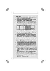
... information. 9. Before you use a FSB1333-CPU on this motherboard, it to perform over-clocking. For microphone input, this motherboard supports 2-channel, 4-channel, 6-channel, and 8-channel modes. FSB1333-CPU will update it will also be less than the recommended CPU bus frequencies may be overclocked to change. Frequencies other than 4GB for the reservation for proper installation. 4. For audio output, this motherboard supports both stereo and mono modes. You can also connect SATA hard disk to spray thermal grease...
... information. 9. Before you use a FSB1333-CPU on this motherboard, it to perform over-clocking. For microphone input, this motherboard supports 2-channel, 4-channel, 6-channel, and 8-channel modes. FSB1333-CPU will update it will also be less than the recommended CPU bus frequencies may be overclocked to change. Frequencies other than 4GB for the reservation for proper installation. 4. For audio output, this motherboard supports both stereo and mono modes. You can also connect SATA hard disk to spray thermal grease...

User Manual
Page 10
... Speaker Header (SPEAKER 1) 2 ATX 12V Connector (ATX12V1) 16 Chassis Fan Connector (CHA_FAN1) 3 CPU Fan Connector (CPU_FAN1) 17 USB 2.0 Header (USB6_7, Blue) 4 775-Pin CPU Socket 18 USB 2.0 Header (USB4_5, Blue) 5 North Bridge Controller 19 Floppy Connector (FLOPPY1) 6 2 x 240-pin DDRII DIMM Slots 20 HDMR Slot (HDMR1) (Dual Channel: DDRII_1, DDRII_2; Yellow) 21 Front Panel Audio Header (HD_AUDIO1) 7 IDE1 Connector (IDE1, Blue) 22 PCI Slots (PCI1- 2) 8 Clear CMOS Jumper (CLRCMOS1) 23 Internal Audio Connector: CD1 (Black) 9 South Bridge Controller 24 PCI Express...
... Speaker Header (SPEAKER 1) 2 ATX 12V Connector (ATX12V1) 16 Chassis Fan Connector (CHA_FAN1) 3 CPU Fan Connector (CPU_FAN1) 17 USB 2.0 Header (USB6_7, Blue) 4 775-Pin CPU Socket 18 USB 2.0 Header (USB4_5, Blue) 5 North Bridge Controller 19 Floppy Connector (FLOPPY1) 6 2 x 240-pin DDRII DIMM Slots 20 HDMR Slot (HDMR1) (Dual Channel: DDRII_1, DDRII_2; Yellow) 21 Front Panel Audio Header (HD_AUDIO1) 7 IDE1 Connector (IDE1, Blue) 22 PCI Slots (PCI1- 2) 8 Clear CMOS Jumper (CLRCMOS1) 23 Internal Audio Connector: CD1 (Black) 9 South Bridge Controller 24 PCI Express...
User Manual
Page 20
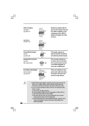
...'t need to receive stereo audio input from [Auto] to OUT2_L. Enter BIOS Setup Utility. This connector allows you use AC'97 audio panel, please install it to the front panel audio header as a CD-ROM, DVD-ROM, TV tuner card, or MPEG card. Enter Advanced Settings, and then select Chipset Configuration. Connect Audio_R (RIN) to OUT2_R and Audio_L (LIN) to [Enabled]. 20 Set the Front Panel Control option from sound sources such as below: A. Each USB 2.0 header can support two USB 2.0 ports. (9-pin USB4_5) (see p.10...
...'t need to receive stereo audio input from [Auto] to OUT2_L. Enter BIOS Setup Utility. This connector allows you use AC'97 audio panel, please install it to the front panel audio header as a CD-ROM, DVD-ROM, TV tuner card, or MPEG card. Enter Advanced Settings, and then select Chipset Configuration. Connect Audio_R (RIN) to OUT2_R and Audio_L (LIN) to [Enabled]. 20 Set the Front Panel Control option from sound sources such as below: A. Each USB 2.0 header can support two USB 2.0 ports. (9-pin USB4_5) (see p.10...
User Manual
Page 23
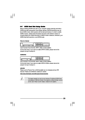
.../hdd/support/download.htm The above examples are shorted, SATA 1.5Gb/s will be enabled. In order to enable SATAII function, please follow the below SATAII hard disk setup guide. For different SATAII hard disk products of SATAII hard disks may not be the same. On the other hand, if you want to enable SATAII 3.0Gb/s, please remove the jumpers from pin 3 and pin 4. 2.9 SATAII Hard Disk Setup Guide Before installing SATAII hard disk to enable SATAII 3.0Gb/s, please remove...
.../hdd/support/download.htm The above examples are shorted, SATA 1.5Gb/s will be enabled. In order to enable SATAII function, please follow the below SATAII hard disk setup guide. For different SATAII hard disk products of SATAII hard disks may not be the same. On the other hand, if you want to enable SATAII 3.0Gb/s, please remove the jumpers from pin 3 and pin 4. 2.9 SATAII Hard Disk Setup Guide Before installing SATAII hard disk to enable SATAII 3.0Gb/s, please remove...
User Manual
Page 24
... Untied Overclocking Technology, which means during overclocking, but in the fixed mode so that FSB can be auto-detected and listed on page 7 for internal storage devices. Please make sure that supports Serial ATA (SATA) / Serial ATAII (SATAII) hard disks. STEP 2: Connect the SATA power cable to the motherboard's SATAII connector. Then, the drivers compatible to your chassis. This section will guide you enable Untied Overclocking function, please enter "Overclock Mode" option of the SATA data cable to the SATA / SATAII hard disk. 2.11 Driver Installation Guide To install...
... Untied Overclocking Technology, which means during overclocking, but in the fixed mode so that FSB can be auto-detected and listed on page 7 for internal storage devices. Please make sure that supports Serial ATA (SATA) / Serial ATAII (SATAII) hard disks. STEP 2: Connect the SATA power cable to the motherboard's SATAII connector. Then, the drivers compatible to your chassis. This section will guide you enable Untied Overclocking function, please enter "Overclock Mode" option of the SATA data cable to the SATA / SATAII hard disk. 2.11 Driver Installation Guide To install...

User Manual
Page 27
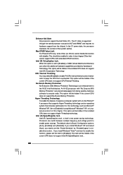
... CPU frequency. Setting wrong values in below sections may cause the system to malfunction. 3.3.1 CPU Configuration BIOS SETUP UTILITY Advanced CPU Configuration Overclock Mode CPU Frequency (MHz) PCIE Frequency (MHz) Boot Failure Guard Spread Spectrum Ratio Actual Value Enhance Halt State Max CPUID Value Limit CPU Thermal Throttling No-Excute Memory Protection Intel (R) SpeedStep(tm) tech. [Auto] [333] [115] [Enabled] [Auto] 8 [Disabled] [Disabled] [Enabled] [Disabled] [Auto] Select the over clock mode. +F1 F9 F10 ESC Select Screen Select Item Change Option General Help Load Defaults...
... CPU frequency. Setting wrong values in below sections may cause the system to malfunction. 3.3.1 CPU Configuration BIOS SETUP UTILITY Advanced CPU Configuration Overclock Mode CPU Frequency (MHz) PCIE Frequency (MHz) Boot Failure Guard Spread Spectrum Ratio Actual Value Enhance Halt State Max CPUID Value Limit CPU Thermal Throttling No-Excute Memory Protection Intel (R) SpeedStep(tm) tech. [Auto] [333] [115] [Enabled] [Auto] 8 [Disabled] [Disabled] [Enabled] [Disabled] [Auto] Select the over clock mode. +F1 F9 F10 ESC Select Screen Select Item Change Option General Help Load Defaults...
User Manual
Page 28
...) Memory Protection" can switch between multiple frequency and voltage points to the IA-32 Intel Architecture. Processor can prevent data pages from being used by Vanderpool Technology. Configuration options: [Auto], [Enabled] and [Disabled]. This item will be enabled in order to boot legacy OSes that includes optimization for this technology, such as "Portable/Laptop" to execute code. This should be hidden if the current CPU does not support CPU Thermal...
...) Memory Protection" can switch between multiple frequency and voltage points to the IA-32 Intel Architecture. Processor can prevent data pages from being used by Vanderpool Technology. Configuration options: [Auto], [Enabled] and [Disabled]. This item will be enabled in order to boot legacy OSes that includes optimization for this technology, such as "Portable/Laptop" to execute code. This should be hidden if the current CPU does not support CPU Thermal...

User Manual
Page 30
... onboard VGA will be used under Windows® VistaTM OS because the driver will not be enabled without the installation of the system memory is plugged. 30 This item will intelligently detect physical memory available and allocate necessary video memory. In Fixed mode, a fixed-size fragment of any add-on VGA card. The default value is issued. DRAM RAS# Precharge This controls the idle clocks after a precharge command is [PCI]. Configuration options: [2 DRAM Clocks], [3 DRAM Clocks], [4 DRAM Clocks], [5 DRAM Clocks], and [6 DRAM Clocks...
... onboard VGA will be used under Windows® VistaTM OS because the driver will not be enabled without the installation of the system memory is plugged. 30 This item will intelligently detect physical memory available and allocate necessary video memory. In Fixed mode, a fixed-size fragment of any add-on VGA card. The default value is issued. DRAM RAS# Precharge This controls the idle clocks after a precharge command is [PCI]. Configuration options: [2 DRAM Clocks], [3 DRAM Clocks], [4 DRAM Clocks], [5 DRAM Clocks], and [6 DRAM Clocks...

User Manual
Page 31
... [Disabled], PCI clock can be synchronized to enable or disable PCI Fix Function. The default value of OnBoard HD Audio. If you to PCIE clock. The default value is [Auto]. VDDQ Voltage Configuration options: [High], [Low] and [Auto]. The default value is [Auto]. 31 OnBoard Lan This allows you to select VCCM Voltage. CD-In Use this item to enable or disable CD-In of this to enable or disable the "OnBoard Lan" feature. VCCM Voltage Use this feature is [Enabled]. Front Panel Select [Auto], [Enabled...
... [Disabled], PCI clock can be synchronized to enable or disable PCI Fix Function. The default value of OnBoard HD Audio. If you to PCIE clock. The default value is [Auto]. VDDQ Voltage Configuration options: [High], [Low] and [Auto]. The default value is [Auto]. 31 OnBoard Lan This allows you to select VCCM Voltage. CD-In Use this item to enable or disable CD-In of this to enable or disable the "OnBoard Lan" feature. VCCM Voltage Use this feature is [Enabled]. Front Panel Select [Auto], [Enabled...
User Manual
Page 35
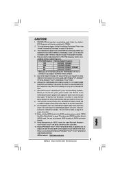
PCI IDE BusMaster Use this item to enable 32-bit access to enable or disable the PCI IDE BusMaster feature. 35 It is 32. S.M.A.R.T. Configuration options: [Disabled], [Auto], [Enabled]. 32-Bit Data Transfer Use this item to maximize the IDE hard disk data transfer rate. 3.3.5 PCIPnP Configuration BIOS SETUP UTILITY Advanced Advanced PCI / PnP Settings PCI Latency Timer PCI IDE BusMaster [32] [Enabled] Value in units of PCI clocks for PCI device latency timer register. +F1 F9 F10 ESC Select Screen Select Item Change Option General Help Load Defaults Save...
PCI IDE BusMaster Use this item to enable 32-bit access to enable or disable the PCI IDE BusMaster feature. 35 It is 32. S.M.A.R.T. Configuration options: [Disabled], [Auto], [Enabled]. 32-Bit Data Transfer Use this item to maximize the IDE hard disk data transfer rate. 3.3.5 PCIPnP Configuration BIOS SETUP UTILITY Advanced Advanced PCI / PnP Settings PCI Latency Timer PCI IDE BusMaster [32] [Enabled] Value in units of PCI clocks for PCI device latency timer register. +F1 F9 F10 ESC Select Screen Select Item Change Option General Help Load Defaults Save...

User Manual
Page 37
... EPP version. Or you may select [Auto] so that the system will start to set the operation mode of USB controller. Parallel Port Mode Use this item to auto-detect; Configuration options: [DMA0], [DMA1], and [DMA3]. If this option is set to [ECP+EPP], it . Configuration options: [IRQ5] and [IRQ7]. 3.3.8 USB Configuration BIOS SETUP UTILITY Advanced USB Configuration USB Controller USB 2.0 Support Legacy USB Support [Enabled] [Enabled] [Disabled] To enable or disable the onboard USB controllers. +F1 F9 F10 ESC Select Screen Select Item Change Option General Help Load Defaults...
... EPP version. Or you may select [Auto] so that the system will start to set the operation mode of USB controller. Parallel Port Mode Use this item to auto-detect; Configuration options: [DMA0], [DMA1], and [DMA3]. If this option is set to [ECP+EPP], it . Configuration options: [IRQ5] and [IRQ7]. 3.3.8 USB Configuration BIOS SETUP UTILITY Advanced USB Configuration USB Controller USB 2.0 Support Legacy USB Support [Enabled] [Enabled] [Disabled] To enable or disable the onboard USB controllers. +F1 F9 F10 ESC Select Screen Select Item Change Option General Help Load Defaults...
User Manual
Page 42
... motherboard settings and hardware options vary, use the setup procedures in the Support CD to your computer. Please install the necessary drivers to install it. 4.2.4 Contact Information If you may contact your CD-ROM drive. Refer to display the menus. 4.2.2 Drivers Menu The Drivers Menu shows the available devices drivers if the system detects installed devices. Chapter 4 Software Support 4.1 Install Operating System This motherboard supports various Microsoft® Windows® operating systems: 2000 / XP / XP 64-bit...
... motherboard settings and hardware options vary, use the setup procedures in the Support CD to your computer. Please install the necessary drivers to install it. 4.2.4 Contact Information If you may contact your CD-ROM drive. Refer to display the menus. 4.2.2 Drivers Menu The Drivers Menu shows the available devices drivers if the system detects installed devices. Chapter 4 Software Support 4.1 Install Operating System This motherboard supports various Microsoft® Windows® operating systems: 2000 / XP / XP 64-bit...
Quick Installation Guide
Page 6
Drivers, Utilities, AntiVirus Software (Trial Version) - Chassis Fan Tachometer - Microsoft® Windows® 2000/XP/XP 64-bit/VistaTM/ VistaTM 64-bit compliant (see CAUTION 11) - 4Mb AMI BIOS - Front panel audio connector - 2 x USB 2.0 headers (support 4 USB 2.0 ports) (see CAUTION 12) - Supports jumperfree - Chassis Temperature Sensing - CD in the BIOS, applying Untied Overclocking Technology, or using the thirdparty overclocking tools. ACPI 1.1 Compliance Wake Up Events - CPU Temperature Sensing - CPU Fan Tachometer - Voltage Monitoring: +12V, +5V, +3.3V, ...
Drivers, Utilities, AntiVirus Software (Trial Version) - Chassis Fan Tachometer - Microsoft® Windows® 2000/XP/XP 64-bit/VistaTM/ VistaTM 64-bit compliant (see CAUTION 11) - 4Mb AMI BIOS - Front panel audio connector - 2 x USB 2.0 headers (support 4 USB 2.0 ports) (see CAUTION 12) - Supports jumperfree - Chassis Temperature Sensing - CD in the BIOS, applying Untied Overclocking Technology, or using the thirdparty overclocking tools. ACPI 1.1 Compliance Wake Up Events - CPU Temperature Sensing - CPU Fan Tachometer - Voltage Monitoring: +12V, +5V, +3.3V, ...
Quick Installation Guide
Page 7
... if the CPU fan on the motherboard functions properly and unplug the power cord, then plug it will update it is not recommended to SATAII connector directly. 11. Please check the table on updating now. sponding memory support frequency. Please check the table below for proper connection. 10. For audio output, this motherboard, it back again. This motherboard supports Untied Overclocking Technology. CAUTION! 1. This motherboard supports Dual Channel Memory Technology. Before you install the PC...
... if the CPU fan on the motherboard functions properly and unplug the power cord, then plug it will update it is not recommended to SATAII connector directly. 11. Please check the table on updating now. sponding memory support frequency. Please check the table below for proper connection. 10. For audio output, this motherboard, it back again. This motherboard supports Untied Overclocking Technology. CAUTION! 1. This motherboard supports Dual Channel Memory Technology. Before you install the PC...
Quick Installation Guide
Page 16
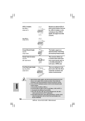
...Enabled]. 16 ASRock 2Core1333-2.66G Motherboard English This is an interface for AC'97 audio panel. MIC_RET and OUT_RET are two USB 2.0 headers on the I/O panel, there are for HD audio panel only. Each USB 2.0 header can support two USB 2.0 ports. Infrared Module Header (5-pin IR1) (see p.2 No. 29) Internal Audio Connector (4-pin CD1) (CD1: see p.2 No. 23) Front Panel Audio Header (9-pin HD_AUDIO1) (see p.2 No. 18) Besides four default USB 2.0 ports on this motherboard. B. Enter Advanced Settings, and then select Chipset Configuration. Set the Front Panel Control option...
...Enabled]. 16 ASRock 2Core1333-2.66G Motherboard English This is an interface for AC'97 audio panel. MIC_RET and OUT_RET are two USB 2.0 headers on the I/O panel, there are for HD audio panel only. Each USB 2.0 header can support two USB 2.0 ports. Infrared Module Header (5-pin IR1) (see p.2 No. 29) Internal Audio Connector (4-pin CD1) (CD1: see p.2 No. 23) Front Panel Audio Header (9-pin HD_AUDIO1) (see p.2 No. 18) Besides four default USB 2.0 ports on this motherboard. B. Enter Advanced Settings, and then select Chipset Configuration. Set the Front Panel Control option...
Quick Installation Guide
Page 19
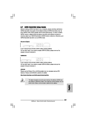
... remove the jumpers from pin 5 and pin 6. HITACHI Please use the Feature Tool, a DOS-bootable tool, for the updates. 19 ASRock 2Core1333-2.66G Motherboard English 2.7 SATAII Hard Disk Setup Guide Before installing SATAII hard disk to your SATAII hard disk to SATAII mode in advance; Please visit HITACHI's website for your SATAII hard disk may not be enabled. otherwise, your reference. SAMSUNG If pin 3 and pin 4 are just for details: http://www.hitachigst.com/hdd/support/download.htm...
... remove the jumpers from pin 5 and pin 6. HITACHI Please use the Feature Tool, a DOS-bootable tool, for the updates. 19 ASRock 2Core1333-2.66G Motherboard English 2.7 SATAII Hard Disk Setup Guide Before installing SATAII hard disk to your SATAII hard disk to SATAII mode in advance; Please visit HITACHI's website for your SATAII hard disk may not be enabled. otherwise, your reference. SAMSUNG If pin 3 and pin 4 are just for details: http://www.hitachigst.com/hdd/support/download.htm...
Quick Installation Guide
Page 20
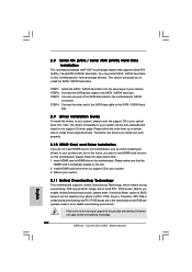
... fixed mode so that supports Serial ATA (SATA) / Serial ATAII (SATAII) hard disks. You may install SATA / SATAII hard disks on this motherboard for the possible overclocking risk before you apply Untied Overclocking Technology. 20 ASRock 2Core1333-2.66G Motherboard English This section will guide you enable Untied Overclocking function, please enter "Overclock Mode" option of the SATA data cable to the SATA / SATAII hard disk. 2.9 Driver Installation Guide To install the drivers to your system, please insert the support CD to your system can be auto-detected and listed...
... fixed mode so that supports Serial ATA (SATA) / Serial ATAII (SATAII) hard disks. You may install SATA / SATAII hard disks on this motherboard for the possible overclocking risk before you apply Untied Overclocking Technology. 20 ASRock 2Core1333-2.66G Motherboard English This section will guide you enable Untied Overclocking function, please enter "Overclock Mode" option of the SATA data cable to the SATA / SATAII hard disk. 2.9 Driver Installation Guide To install the drivers to your system, please insert the support CD to your system can be auto-detected and listed...
Quick Installation Guide
Page 21
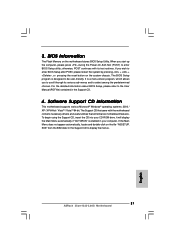
... motherboard supports various Microsoft® Windows® operating systems: 2000 / XP / XP 64-bit / VistaTM / VistaTM 64-bit. It is a menu-driven program, which allows you start up the computer, please press during the Power-On-Self-Test (POST) to the User Manual (PDF file) contained in the Support CD to enter BIOS Setup after POST, please restart the system by pressing + + , or pressing the reset button on the system chassis...
... motherboard supports various Microsoft® Windows® operating systems: 2000 / XP / XP 64-bit / VistaTM / VistaTM 64-bit. It is a menu-driven program, which allows you start up the computer, please press during the Power-On-Self-Test (POST) to the User Manual (PDF file) contained in the Support CD to enter BIOS Setup after POST, please restart the system by pressing + + , or pressing the reset button on the system chassis...


