
User Guide
Page 3
... Reference Guide The Command Reference Guide explains how to use the web configurator to configure the Switch. • Support Disc Refer to configure the Switch. Note: It is intended for support documents. READ CAREFULLY BEFORE USE. MES3500-24/24F User's Guide 3 KEEP THIS GUIDE FOR FUTURE REFERENCE. Intended Audience This manual is recommended you use...
... Reference Guide The Command Reference Guide explains how to use the web configurator to configure the Switch. • Support Disc Refer to configure the Switch. Note: It is intended for support documents. READ CAREFULLY BEFORE USE. MES3500-24/24F User's Guide 3 KEEP THIS GUIDE FOR FUTURE REFERENCE. Intended Audience This manual is recommended you use...

User Guide
Page 4
... menu and finally the Log Setting tab to get to configure or helpful tips) or recommendations. The Switch Computer Notebook computer Server DSLAM Firewall Telephone Switch Router 4 MES3500-24/24F User's Guide Document Conventions Document Conventions Warnings and Notes These are how warnings and notes are all in... bold font. • A key stroke is not an exact representation of your device. Syntax Conventions • The MES3500-24/24F may be referred to as the "Switch", the "device", the "system" or the "product" in this User's Guide. • Product labels, screen names, ...
... menu and finally the Log Setting tab to get to configure or helpful tips) or recommendations. The Switch Computer Notebook computer Server DSLAM Firewall Telephone Switch Router 4 MES3500-24/24F User's Guide Document Conventions Document Conventions Warnings and Notes These are how warnings and notes are all in... bold font. • A key stroke is not an exact representation of your device. Syntax Conventions • The MES3500-24/24F may be referred to as the "Switch", the "device", the "system" or the "product" in this User's Guide. • Product labels, screen names, ...

User Guide
Page 7
Contents Overview Contents Overview User's Guide ...21 Getting to Know Your Switch ...23 Hardware Installation and Connection 27 Hardware Overview ...30 The Web Configurator ...39 Initial Setup Example ...49 Tutorials ...53 Technical Reference ...79 System Status and ... Guard ...233 VLAN Mapping ...237 Layer 2 Protocol Tunneling ...241 sFlow ...245 PPPoE ...249 Error Disable ...257 Private VLAN ...262 Static Route ...265 Differentiated Services ...268 MES3500-24/24F User's Guide 7
Contents Overview Contents Overview User's Guide ...21 Getting to Know Your Switch ...23 Hardware Installation and Connection 27 Hardware Overview ...30 The Web Configurator ...39 Initial Setup Example ...49 Tutorials ...53 Technical Reference ...79 System Status and ... Guard ...233 VLAN Mapping ...237 Layer 2 Protocol Tunneling ...241 sFlow ...245 PPPoE ...249 Error Disable ...257 Private VLAN ...262 Static Route ...265 Differentiated Services ...268 MES3500-24/24F User's Guide 7
User Guide
Page 9
...I: User's Guide 21 Chapter 1 Getting to Know Your Switch 23 1.1 Introduction ...23 1.1.1 Backbone Application 23 1.1.2 Bridging Example ...24 1.1.3 High Performance Switching Example 24 1.1.4 IEEE 802.1Q VLAN Application Examples 25 1.1.5 IPv6 ...Switch on a Rack 27 2.3.1 Rack-mounted Installation Requirements 27 2.3.2 Attaching the Mounting Brackets to the Switch 28 2.3.3 Mounting the Switch on a Rack 29 Chapter 3 Hardware Overview ...30 3.1 Front Panel ...30 3.1.1 Console Port ...31 3.1.2 Ethernet Ports ...32 3.1.3 Transceiver Slots ...32 3.1.4 Power Connector ...34 MES3500-24/24F...
...I: User's Guide 21 Chapter 1 Getting to Know Your Switch 23 1.1 Introduction ...23 1.1.1 Backbone Application 23 1.1.2 Bridging Example ...24 1.1.3 High Performance Switching Example 24 1.1.4 IEEE 802.1Q VLAN Application Examples 25 1.1.5 IPv6 ...Switch on a Rack 27 2.3.1 Rack-mounted Installation Requirements 27 2.3.2 Attaching the Mounting Brackets to the Switch 28 2.3.3 Mounting the Switch on a Rack 29 Chapter 3 Hardware Overview ...30 3.1 Front Panel ...30 3.1.1 Console Port ...31 3.1.2 Ethernet Ports ...32 3.1.3 Transceiver Slots ...32 3.1.4 Power Connector ...34 MES3500-24/24F...
User Guide
Page 10
... 4.3 The Web Configurator Layout 40 4.3.1 Change Your Password 44 4.4 Saving Your Configuration 44 4.5 Switch Lockout ...44 4.6 Resetting the Switch ...45 4.6.1 Reload the Configuration File 45 4.7 Logging Out of the Web Configurator 46 4.8 Help...Switch B 63 6.4 How to Use Error Disable and Recovery on the Switch 66 6.5 How to Set Up a Guest VLAN 68 6.5.1 Creating a Guest VLAN 68 6.5.2 Enabling IEEE 802.1x Port Authentication 71 6.5.3 Enabling Guest VLAN 72 6.6 How to Do Port Isolation in a VLAN 73 6.6.1 Creating a VLAN ...74 6.6.2 Creating a Private VLAN Rule 76 10 MES3500-24/24F...
... 4.3 The Web Configurator Layout 40 4.3.1 Change Your Password 44 4.4 Saving Your Configuration 44 4.5 Switch Lockout ...44 4.6 Resetting the Switch ...45 4.6.1 Reload the Configuration File 45 4.7 Logging Out of the Web Configurator 46 4.8 Help...Switch B 63 6.4 How to Use Error Disable and Recovery on the Switch 66 6.5 How to Set Up a Guest VLAN 68 6.5.1 Creating a Guest VLAN 68 6.5.2 Enabling IEEE 802.1x Port Authentication 71 6.5.3 Enabling Guest VLAN 72 6.6 How to Do Port Isolation in a VLAN 73 6.6.1 Creating a VLAN ...74 6.6.2 Creating a Private VLAN Rule 76 10 MES3500-24/24F...
User Guide
Page 11
... Summary ...81 7.2.1 Status: Port Details 83 Chapter 8 Basic Setting ...86 8.1 Overview ...86 8.2 System Information ...86 8.3 General Setup ...88 8.4 Introduction to VLANs ...89 8.4.1 Smart Isolation ...90 8.5 Switch Setup ...91 8.6 IP Setup ...93 8.6.1 Management IP Addresses 93 8.7 Port Setup ...95 Chapter 9 VLAN ...97 9.1 Introduction to IEEE 802.1Q Tagged VLANs 97 9.1.1 Forwarding Tagged... 9.9 Configuring Protocol Based VLAN 108 9.10 Create an IP-based VLAN Example 109 9.11 Port-based VLAN Setup 110 9.11.1 Configure a Port-based VLAN 111 MES3500-24/24F User's Guide 11
... Summary ...81 7.2.1 Status: Port Details 83 Chapter 8 Basic Setting ...86 8.1 Overview ...86 8.2 System Information ...86 8.3 General Setup ...88 8.4 Introduction to VLANs ...89 8.4.1 Smart Isolation ...90 8.5 Switch Setup ...91 8.6 IP Setup ...93 8.6.1 Management IP Addresses 93 8.7 Port Setup ...95 Chapter 9 VLAN ...97 9.1 Introduction to IEEE 802.1Q Tagged VLANs 97 9.1.1 Forwarding Tagged... 9.9 Configuring Protocol Based VLAN 108 9.10 Create an IP-based VLAN Example 109 9.11 Port-based VLAN Setup 110 9.11.1 Configure a Port-based VLAN 111 MES3500-24/24F User's Guide 11

User Guide
Page 18
... 298 38.4 Setting Up Login Accounts 299 38.5 SSH Overview ...301 38.6 How SSH works ...302 38.7 SSH Implementation on the Switch 303 38.7.1 Requirements for Using SSH 303 38.8 Introduction to HTTPS ...303 38.9 HTTPS Example ...304 38.9.1 Internet Explorer Warning Messages ... Cluster Management ...316 41.1 Cluster Management Status Overview 316 41.2 Cluster Management Status 317 41.2.1 Cluster Member Switch Management 318 41.3 Clustering Management Configuration 320 Chapter 42 MAC Table ...322 42.1 MAC Table Overview ...322 42.2 Viewing the MAC Table 323 18 MES3500-24/24F User's Guide
... 298 38.4 Setting Up Login Accounts 299 38.5 SSH Overview ...301 38.6 How SSH works ...302 38.7 SSH Implementation on the Switch 303 38.7.1 Requirements for Using SSH 303 38.8 Introduction to HTTPS ...303 38.9 HTTPS Example ...304 38.9.1 Internet Explorer Warning Messages ... Cluster Management ...316 41.1 Cluster Management Status Overview 316 41.2 Cluster Management Status 317 41.2.1 Cluster Member Switch Management 318 41.3 Clustering Management Configuration 320 Chapter 42 MAC Table ...322 42.1 MAC Table Overview ...322 42.2 Viewing the MAC Table 323 18 MES3500-24/24F User's Guide
User Guide
Page 19
Table of Contents Chapter 43 ARP Table ...325 43.1 ARP Table Overview ...325 43.1.1 How ARP Works ...325 43.2 The ARP Table Screen ...326 Chapter 44 Configure Clone...327 44.1 Configure Clone ...327 Chapter 45 Troubleshooting...329 45.1 Power, Hardware Connections, and LEDs 329 45.2 Switch Access and Login 330 45.3 Switch Configuration ...332 Appendix A Common Services 333 Appendix B Legal Information 337 Index ...341 MES3500-24/24F User's Guide 19
Table of Contents Chapter 43 ARP Table ...325 43.1 ARP Table Overview ...325 43.1.1 How ARP Works ...325 43.2 The ARP Table Screen ...326 Chapter 44 Configure Clone...327 44.1 Configure Clone ...327 Chapter 45 Troubleshooting...329 45.1 Power, Hardware Connections, and LEDs 329 45.2 Switch Access and Login 330 45.3 Switch Configuration ...332 Appendix A Common Services 333 Appendix B Legal Information 337 Index ...341 MES3500-24/24F User's Guide 19
User Guide
Page 23
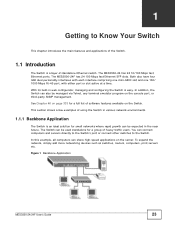
... example, all computers can also be used standalone for a full list of heavy traffic users. Figure 1 Backbone Application MES3500-24/24F User's Guide 23 The MES3500-24F has 24 100 Mbps fast Ethernet SFP slots. In addition, the Switch can share high-speed applications on the server. To expand the network, simply add more networking devices such...
... example, all computers can also be used standalone for a full list of heavy traffic users. Figure 1 Backbone Application MES3500-24/24F User's Guide 23 The MES3500-24F has 24 100 Mbps fast Ethernet SFP slots. In addition, the Switch can share high-speed applications on the server. To expand the network, simply add more networking devices such...
User Guide
Page 24
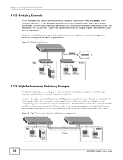
... communicate with each other. Chapter 1 Getting to Know Your Switch 1.1.2 Bridging Example In this example, the Switch connects different company departments (RD and Sales) to connect these two networks. In the following example, use existing adapters and switches. Figure 3 High Performance Switched Workgroup Application 24 MES3500-24/24F User's Guide Moreover, the current LAN structure can be retained...
... communicate with each other. Chapter 1 Getting to Know Your Switch 1.1.2 Bridging Example In this example, the Switch connects different company departments (RD and Sales) to connect these two networks. In the following example, use existing adapters and switches. Figure 3 High Performance Switched Workgroup Application 24 MES3500-24/24F User's Guide Moreover, the current LAN structure can be retained...

User Guide
Page 25
...Ports in IPv6 address size to 128 bits (from stations that need access to the server need to 3.4 x 1038 IP addresses. MES3500-24/24F User's Guide 25 the Switch can run IPv4 and IPv6 at any re-cabling. Stations on IPv6, refer to one group. Shared resources such as a server ... VLAN (Virtual Local Area Network) allows a physical network to enhance IP address size and features. A station can be part of writing, the Switch supports the following figure only ports that are not in packet processing and perform diagnostic functions, such as the server. At the time of VLAN...
...Ports in IPv6 address size to 128 bits (from stations that need access to the server need to 3.4 x 1038 IP addresses. MES3500-24/24F User's Guide 25 the Switch can run IPv4 and IPv6 at any re-cabling. Stations on IPv6, refer to one group. Shared resources such as a server ... VLAN (Virtual Local Area Network) allows a physical network to enhance IP address size and features. A station can be part of writing, the Switch supports the following figure only ports that are not in packet processing and perform diagnostic functions, such as the server. At the time of VLAN...
User Guide
Page 26
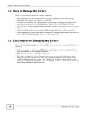
...monitored by an SNMP manager. See Chapter 4 on page 290. • Cluster Management. If you backed up the configuration (and make the Switch more effectively. • Change the password. Line commands offer an alternative to the web configurator and in a safe place. • Back...are necessary to restore it). If you forget your last configuration. 26 MES3500-24/24F User's Guide See Section 37.8 on page 316. 1.3 Good Habits for Managing the Switch Do the following methods to manage the Switch. • Web Configurator. Use FTP for everyday management of the following...
...monitored by an SNMP manager. See Chapter 4 on page 290. • Cluster Management. If you backed up the configuration (and make the Switch more effectively. • Change the password. Line commands offer an alternative to the web configurator and in a safe place. • Back...are necessary to restore it). If you forget your last configuration. 26 MES3500-24/24F User's Guide See Section 37.8 on page 316. 1.3 Good Habits for Managing the Switch Do the following methods to manage the Switch. • Web Configurator. Use FTP for everyday management of the following...
User Guide
Page 27
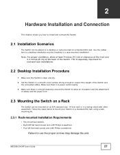
... steps below to allow at least 4 inches (10 cm) of clearance at the front and 3.4 inches (8 cm) at the back of the Switch and the connected cables. MES3500-24/24F User's Guide 27 Failure to support the weight of the Switch. This is especially important for enclosed rack installations. 2.2 Desktop Installation Procedure 1 Make sure the...
... steps below to allow at least 4 inches (10 cm) of clearance at the front and 3.4 inches (8 cm) at the back of the Switch and the connected cables. MES3500-24/24F User's Guide 27 Failure to support the weight of the Switch. This is especially important for enclosed rack installations. 2.2 Desktop Installation Procedure 1 Make sure the...
User Guide
Page 28
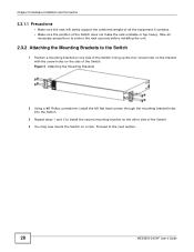
...to anchor the rack securely before installing the unit. 2.3.2 Attaching the Mounting Brackets to the Switch 1 Position a mounting bracket on one side of the Switch, lining up the four screw holes on the bracket with the screw holes on the side...Switch. Take all the equipment it contains. • Make sure the position of the Switch. 4 You may now mount the Switch on a rack. Figure 5 Attaching the Mounting Brackets 2 Using a #2 Philips screwdriver, install the M3 flat head screws through the mounting bracket holes into the Switch. 3 Repeat steps 1 and 2 to the next section. 28 MES3500-24/24F...
...to anchor the rack securely before installing the unit. 2.3.2 Attaching the Mounting Brackets to the Switch 1 Position a mounting bracket on one side of the Switch, lining up the four screw holes on the bracket with the screw holes on the side...Switch. Take all the equipment it contains. • Make sure the position of the Switch. 4 You may now mount the Switch on a rack. Figure 5 Attaching the Mounting Brackets 2 Using a #2 Philips screwdriver, install the M3 flat head screws through the mounting bracket holes into the Switch. 3 Repeat steps 1 and 2 to the next section. 28 MES3500-24/24F...
User Guide
Page 29
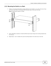
MES3500-24/24F User's Guide 29 Chapter 2 Hardware Installation and Connection 2.3.3 Mounting the Switch on a Rack 1 Position a mounting bracket (that is already attached to attach the second mounting bracket on the side of the rack. Figure 6 Mounting the Switch on a Rack 2 Using a #2 Philips screwdriver, install the M5 flat head screws through the mounting bracket holes into the rack. 3 Repeat steps 1 and 2 to the Switch) on one side of the rack, lining up the two screw holes on the bracket with the screw holes on the other side of the rack.
MES3500-24/24F User's Guide 29 Chapter 2 Hardware Installation and Connection 2.3.3 Mounting the Switch on a Rack 1 Position a mounting bracket (that is already attached to attach the second mounting bracket on the side of the rack. Figure 6 Mounting the Switch on a Rack 2 Using a #2 Philips screwdriver, install the M5 flat head screws through the mounting bracket holes into the rack. 3 Repeat steps 1 and 2 to the Switch) on one side of the rack, lining up the two screw holes on the bracket with the screw holes on the other side of the rack.
User Guide
Page 30
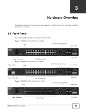
... Interfaces Console Port Power Connection Fast Ethernet Ports Figure 8 MES3500-24 Front Panel: DC Model Power Switch LEDs Signal slot Dual Personality Interfaces Console Port Power Connection Fast Ethernet Ports Figure 9 MES3500-24F Front Panel: AC Model LEDs Signal slot Dual Personality Interfaces Console Port Power Connection MES3500-24/24F User's Guide Fast SFP Slots Signal slot 30
... Interfaces Console Port Power Connection Fast Ethernet Ports Figure 8 MES3500-24 Front Panel: DC Model Power Switch LEDs Signal slot Dual Personality Interfaces Console Port Power Connection Fast Ethernet Ports Figure 9 MES3500-24F Front Panel: AC Model LEDs Signal slot Dual Personality Interfaces Console Port Power Connection MES3500-24/24F User's Guide Fast SFP Slots Signal slot 30
User Guide
Page 31
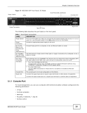
... transceivers in the ON position to the following table describes the port labels on the Switch. Table 1 Front Panel Connections LABEL Power Switch Power Connection 24 10/100 Mbps RJ-45 Fast Ethernet Ports (MES3500-24) 24 100 Mbps Fast SFP Slots (MES3500-24F) Four Dual Personality Interfaces Console Port Signal slot DESCRIPTION This is for fiber-optic...
... transceivers in the ON position to the following table describes the port labels on the Switch. Table 1 Front Panel Connections LABEL Power Switch Power Connection 24 10/100 Mbps RJ-45 Fast Ethernet Ports (MES3500-24) 24 100 Mbps Fast SFP Slots (MES3500-24F) Four Dual Personality Interfaces Console Port Signal slot DESCRIPTION This is for fiber-optic...
User Guide
Page 32
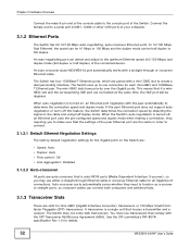
...MSA). See the SFF committee's INF-8074i specification Rev 1.0 for all Gigabit port connections. When the Switch's auto-negotiation is turned on, an Ethernet port negotiates with the peer automatically to connect. 3.1.2.1 Default ...on the cable and using half duplex mode. The Switch does not come with a straight-through Ethernet cable or crossover Ethernet cable for details. 32 MES3500-24/24F User's Guide In 10/100 Mbps Fast Ethernet, ... the settings of your computer. 3.1.2 Ethernet Ports The Switch has 24 10/100 Mbps auto-negotiating, auto-crossover Ethernet ports.
...MSA). See the SFF committee's INF-8074i specification Rev 1.0 for all Gigabit port connections. When the Switch's auto-negotiation is turned on, an Ethernet port negotiates with the peer automatically to connect. 3.1.2.1 Default ...on the cable and using half duplex mode. The Switch does not come with a straight-through Ethernet cable or crossover Ethernet cable for details. 32 MES3500-24/24F User's Guide In 10/100 Mbps Fast Ethernet, ... the settings of your computer. 3.1.2 Ethernet Ports The Switch has 24 10/100 Mbps auto-negotiating, auto-crossover Ethernet ports.
User Guide
Page 33
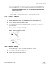
... Use the following steps to install a mini-GBIC transceiver (SFP module). 1 Insert the transceiver into place. 3 The Switch automatically detects the installed transceiver. Figure 11 Transceiver Installation Example Figure 12 Connecting the Fiber Optic Cables 3.1.3.2 Transceiver Removal Use ...switches with the exposed section of PCB board facing down. 2 Press the transceiver firmly until it clicks into the slot with different types of fiber-optic or even copper cable connectors. Chapter 3 Hardware Overview You can use different transceivers to connect to the transceiver. MES3500-24/24F...
... Use the following steps to install a mini-GBIC transceiver (SFP module). 1 Insert the transceiver into place. 3 The Switch automatically detects the installed transceiver. Figure 11 Transceiver Installation Example Figure 12 Connecting the Fiber Optic Cables 3.1.3.2 Transceiver Removal Use ...switches with the exposed section of PCB board facing down. 2 Press the transceiver firmly until it clicks into the slot with different types of fiber-optic or even copper cable connectors. Chapter 3 Hardware Overview You can use different transceivers to connect to the transceiver. MES3500-24/24F...

User Guide
Page 292
... the temperature returns to the normal operating range. 292 MES3500-24/24F User's Guide An OID (Object ID) that begins with "1.3.6.1.4.1.890.1.5.8.68" are specific to an SNMP manager when an event occurs. Otherwise, it is sent when the Switch restarts. This trap is sent when the voltage goes ...MIB for IP, RFC 2012 SNMPv2 MIB for TCP, RFC 2013 SNMPv2 MIB for UDP 38.3.3 SNMP Traps The Switch sends traps to the MES3500-24F switch. This trap is turned on. The Switch supports the following tables outline the SNMP traps by category. The following MIBs: • SNMP MIB II (...
... the temperature returns to the normal operating range. 292 MES3500-24/24F User's Guide An OID (Object ID) that begins with "1.3.6.1.4.1.890.1.5.8.68" are specific to an SNMP manager when an event occurs. Otherwise, it is sent when the Switch restarts. This trap is sent when the voltage goes ...MIB for IP, RFC 2012 SNMPv2 MIB for TCP, RFC 2013 SNMPv2 MIB for UDP 38.3.3 SNMP Traps The Switch sends traps to the MES3500-24F switch. This trap is turned on. The Switch supports the following tables outline the SNMP traps by category. The following MIBs: • SNMP MIB II (...