

Operating Guide
Page 1
Installation, Setup & Operating Guide I Warranty Model Number | L15V26D | LCD-TV / Monitor © Copyright 2004, LG Electronics USA, Inc.
Installation, Setup & Operating Guide I Warranty Model Number | L15V26D | LCD-TV / Monitor © Copyright 2004, LG Electronics USA, Inc.

Operating Guide
Page 2
... a Class B digital device, pursuant to modify this product. These limits are located on a circuit different from Zenith Electronics Corporation. NOTE TO CABLE/TV INSTALLER: This reminder is operated in a particular installation. For convenience, we suggest that the cable ground shall be of sufficient magnitude to the point of the FCC Rules. The lightning flash with the instruction manual, may be connected to...
... a Class B digital device, pursuant to modify this product. These limits are located on a circuit different from Zenith Electronics Corporation. NOTE TO CABLE/TV INSTALLER: This reminder is operated in a particular installation. For convenience, we suggest that the cable ground shall be of sufficient magnitude to the point of the FCC Rules. The lightning flash with the instruction manual, may be connected to...

Operating Guide
Page 3
... operating instructions should be adhered to . 11. If you are not sure of the type of the product and to insert the plug fully into your electrician to overturn. 10. Power-Cord Polarization This product is a safety feature. If you are unable to protect it from the product. (Continued on an unstable cart, stand, tripod, bracket, or table. Power-Cord Protection Power-supply cords...
... operating instructions should be adhered to . 11. If you are not sure of the type of the product and to insert the plug fully into your electrician to overturn. 10. Power-Cord Polarization This product is a safety feature. If you are unable to protect it from the product. (Continued on an unstable cart, stand, tripod, bracket, or table. Power-Cord Protection Power-supply cords...
Operating Guide
Page 4
... mounted to qualified service personnel under the following the operating instructions. When installing an outside antenna or cable system is left unattended and unused for the grounding electrode. Damage Requiring Service Unplug this product through openings as recommended by the operating instructions as to rain or water. b. Adjust only those controls that produce heat. 4 f. Replacement Parts When replacement parts are covered by the manufacturer. Wall or Ceiling Mounting...
... mounted to qualified service personnel under the following the operating instructions. When installing an outside antenna or cable system is left unattended and unused for the grounding electrode. Damage Requiring Service Unplug this product through openings as recommended by the operating instructions as to rain or water. b. Adjust only those controls that produce heat. 4 f. Replacement Parts When replacement parts are covered by the manufacturer. Wall or Ceiling Mounting...

Operating Guide
Page 5
... Overview 11 2 Antenna/Cable Connections VCR Connection and Viewing Setup 13 15 External Equipment Connections 16 DVD Player Connections 17 DTV (Set-top box) Connections 18 PC/Computer Connections 19 PC Mode Functions Check 21 3 Turning the TV On 22 TV Mode Menus 23 Menu Language Selection 24 Auto Programming: Finding/Erasing channels 25 Favorite Channel Memory 27 4 Clock Setup 28 Off Timer Setup 29 On Timer Setup 30 Sleep Timer Setup 31 5 Video/Picture Setup 32 Audio/Sound Setup 35 Closed Captions 41 6 Parental Control 44 Auto Off 47 Key lock 48...
... Overview 11 2 Antenna/Cable Connections VCR Connection and Viewing Setup 13 15 External Equipment Connections 16 DVD Player Connections 17 DTV (Set-top box) Connections 18 PC/Computer Connections 19 PC Mode Functions Check 21 3 Turning the TV On 22 TV Mode Menus 23 Menu Language Selection 24 Auto Programming: Finding/Erasing channels 25 Favorite Channel Memory 27 4 Clock Setup 28 Off Timer Setup 29 On Timer Setup 30 Sleep Timer Setup 31 5 Video/Picture Setup 32 Audio/Sound Setup 35 Closed Captions 41 6 Parental Control 44 Auto Off 47 Key lock 48...

Operating Guide
Page 7
DVD/DTV IN (Component (480i, 480p,720p,1080i) Input PC Input PC Sound Antenna Input 7 Never attempt to operate the S-Video Input Headphone Jack Audio/Video Input TV on AC power. INTRODUCTION Back of the TV Connection Panel AC INPUT Y PB PR COMPONENT(480i/480p/720p/1080i) DVD/DTV IN H/P S-VIDEO VIDEO(MONO) L AUDIO R VIDEO IN PC INPUT ANT IN +75 Ω PC SOUND Power Cord Socket - This TV operates on DC power.
DVD/DTV IN (Component (480i, 480p,720p,1080i) Input PC Input PC Sound Antenna Input 7 Never attempt to operate the S-Video Input Headphone Jack Audio/Video Input TV on AC power. INTRODUCTION Back of the TV Connection Panel AC INPUT Y PB PR COMPONENT(480i/480p/720p/1080i) DVD/DTV IN H/P S-VIDEO VIDEO(MONO) L AUDIO R VIDEO IN PC INPUT ANT IN +75 Ω PC SOUND Power Cord Socket - This TV operates on DC power.

Operating Guide
Page 11
VESA standard mounting interface - Arrange the wires with the tie band. If you intend to mount the TV to a wall, attach this plate to the back of the TV. 11 INTRODUCTION TV Overview Accessories power tv/video 1 2 3 4 5 6 7 8 9 apc cc 0 menu mute ch vol enter vol mts ch sleep fcr flashbk dasp a.prog memory/erase Remote control 1.5V 1.5V AAA Batteries Operating guide Power cord PC signal cable PC sound cable Tie bands -
VESA standard mounting interface - Arrange the wires with the tie band. If you intend to mount the TV to a wall, attach this plate to the back of the TV. 11 INTRODUCTION TV Overview Accessories power tv/video 1 2 3 4 5 6 7 8 9 apc cc 0 menu mute ch vol enter vol mts ch sleep fcr flashbk dasp a.prog memory/erase Remote control 1.5V 1.5V AAA Batteries Operating guide Power cord PC signal cable PC sound cable Tie bands -

Operating Guide
Page 13
...; Flat Wire Antenna Converter PC INPUT ANT IN +75 Ω PC SOUND Antenna jack - If you have a 75Ω round cable, insert the bronze wire and then tighten the connection nut. Connecting to an Outdoor Antenna Setup q This type of wall antenna jack.) Turn clockwise to get better picture quality, install the antenna as shown below. (Use the correct type of antenna cable for the type of antenna is split for two TVs, use signal...
...; Flat Wire Antenna Converter PC INPUT ANT IN +75 Ω PC SOUND Antenna jack - If you have a 75Ω round cable, insert the bronze wire and then tighten the connection nut. Connecting to an Outdoor Antenna Setup q This type of wall antenna jack.) Turn clockwise to get better picture quality, install the antenna as shown below. (Use the correct type of antenna cable for the type of antenna is split for two TVs, use signal...
Operating Guide
Page 14
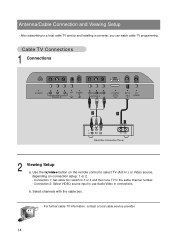
...Connection 2: Select VIDEO source input to the same channel number. - Select channels with the cable box. - Antenna/Cable Connection and Viewing Setup - Connection 1: Set cable box switch to 3 or 4 and then tune TV to use Audio/Video In connections. Cable TV Connections 1 Connections AC INPUT Y PB PR H/P S-VIDEO COMPONENT(480i/480p/720p/1080i) DVD/DTV IN VIDEO(MONO) L AUDIO R VIDEO IN PC INPUL T ANT IN +75 Ω PC SOUND 2 1 (R) AUDIO (L) VIDEO TV VCR RF Cable Cable Box Connection Panel 2 Viewing Setup a. b. For further cable TV information, contact a local cable...
...Connection 2: Select VIDEO source input to the same channel number. - Select channels with the cable box. - Antenna/Cable Connection and Viewing Setup - Connection 1: Set cable box switch to 3 or 4 and then tune TV to use Audio/Video In connections. Cable TV Connections 1 Connections AC INPUT Y PB PR H/P S-VIDEO COMPONENT(480i/480p/720p/1080i) DVD/DTV IN VIDEO(MONO) L AUDIO R VIDEO IN PC INPUL T ANT IN +75 Ω PC SOUND 2 1 (R) AUDIO (L) VIDEO TV VCR RF Cable Cable Box Connection Panel 2 Viewing Setup a. b. For further cable TV information, contact a local cable...

Operating Guide
Page 15
... CH4 (R) AUDIO(L) VIDEO VCR Connection Panel 2 Viewing Setup Watching TV programs Turn the TV on the TV. Watching VCR a. See following pages to connect to other A/V external equipment to input jacks on and tune to the corresponding input jacks on connection setup: 1 or 2. - Connecting a VCR 1 Connections q Connect the audio/video output jacks on VCR to a channel. Connection 2: Select VIDEO source input to the same channel number. - Use tv/video button on the remote control to TV mode if the fcr button or flashbk buttons are...
... CH4 (R) AUDIO(L) VIDEO VCR Connection Panel 2 Viewing Setup Watching TV programs Turn the TV on the TV. Watching VCR a. See following pages to connect to other A/V external equipment to input jacks on and tune to the corresponding input jacks on connection setup: 1 or 2. - Connecting a VCR 1 Connections q Connect the audio/video output jacks on VCR to a channel. Connection 2: Select VIDEO source input to the same channel number. - Use tv/video button on the remote control to TV mode if the fcr button or flashbk buttons are...
Operating Guide
Page 16
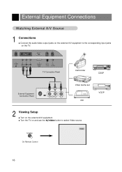
External Equipment Connections Watching External A/V Source 1 Connections q Connect the audio/video output jacks on the external A/V equipment to select Video source. tv/video Video On Remote Control 16 S-VIDEO VIDEO(MONO) L AUDIO R VIDEO IN PC INPUT ANT IN +75 Ω PC SOUND TV Connection Panel Camcorder CDGP External Equipment Connection Panel R AUDIO L VIDEO Video Game set CDI VCDP 2 Viewing Setup q Turn on the TV. q Turn the TV on and use the tv/video button to the corresponding input jacks on the external A/V equipment.
External Equipment Connections Watching External A/V Source 1 Connections q Connect the audio/video output jacks on the external A/V equipment to select Video source. tv/video Video On Remote Control 16 S-VIDEO VIDEO(MONO) L AUDIO R VIDEO IN PC INPUT ANT IN +75 Ω PC SOUND TV Connection Panel Camcorder CDGP External Equipment Connection Panel R AUDIO L VIDEO Video Game set CDI VCDP 2 Viewing Setup q Turn on the TV. q Turn the TV on and use the tv/video button to the corresponding input jacks on the external A/V equipment.
Operating Guide
Page 17
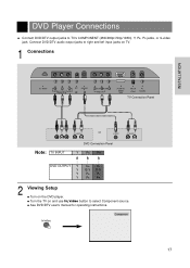
.../720p/1080i) DVD/DTV IN VIDEO(MONO) L AUDIO R VIDEO IN PC INPUL T ANT IN +75 Ω PC SOUND TV Connection Panel INSTALLATION Y PB PR (R) AUDIO (L) or S-VIDEO (R) AUDIO (L) Note: TV INPUT DVD Connection Panel Y PB PR DVD OUTPUT Y Y Y Y Cb Cr B-Y R-Y Pb Pr PB PR 2 Viewing Setup q Turn on and use tv/video button to TV's COMPONENT (480i/480p/720p/1080i), Y, PB, PR jacks, or S-video jack. q See DVD/DTV user's manual for operating instructions. DVD Player Connections q Connect DVD/DTV output jacks to select Component source. tv/video Component 17
.../720p/1080i) DVD/DTV IN VIDEO(MONO) L AUDIO R VIDEO IN PC INPUL T ANT IN +75 Ω PC SOUND TV Connection Panel INSTALLATION Y PB PR (R) AUDIO (L) or S-VIDEO (R) AUDIO (L) Note: TV INPUT DVD Connection Panel Y PB PR DVD OUTPUT Y Y Y Y Cb Cr B-Y R-Y Pb Pr PB PR 2 Viewing Setup q Turn on and use tv/video button to TV's COMPONENT (480i/480p/720p/1080i), Y, PB, PR jacks, or S-video jack. q See DVD/DTV user's manual for operating instructions. DVD Player Connections q Connect DVD/DTV output jacks to select Component source. tv/video Component 17
Operating Guide
Page 18
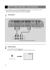
.../video Component On Remote Control 18 q Turn the TV on the DTV receiver (Set-top Box). Note: A DTV set-top box is required to receive DTV programming. 1 Connections AC INPUT Y PB PR H/P S-VIDEO COMPONENT(480i/480p/720p/1080i) DVD/DTV IN VIDEO(MONO) L AUDIO R VIDEO IN PC INPUL T ANT IN +75 Ω PC SOUND TV Connections Panel Y PB PR (R) AUDIO (L) DTV Receiver (Set-top Box) Connections Panel 2 Viewing Setup q Turn on and use tv/video button to select Component source. DTV (Set-top Box) Connections q Connect DVD/DTV output to the TV's AUDIO L/R input jacks...
.../video Component On Remote Control 18 q Turn the TV on the DTV receiver (Set-top Box). Note: A DTV set-top box is required to receive DTV programming. 1 Connections AC INPUT Y PB PR H/P S-VIDEO COMPONENT(480i/480p/720p/1080i) DVD/DTV IN VIDEO(MONO) L AUDIO R VIDEO IN PC INPUL T ANT IN +75 Ω PC SOUND TV Connections Panel Y PB PR (R) AUDIO (L) DTV Receiver (Set-top Box) Connections Panel 2 Viewing Setup q Turn on and use tv/video button to select Component source. DTV (Set-top Box) Connections q Connect DVD/DTV output to the TV's AUDIO L/R input jacks...

Operating Guide
Page 19
...'s PC SOUND input. q Connect the PC audio output to the PC with the PC cable. INSTALLATION VIDEO(MONO) L AUDIO R VIDEO IN TV Connections Panel PC INPUT ANT IN +75 Ω PC SOUND PC Connections Panel 2 Viewing Setup q Turn on the PC before connecting to the TV. After setup, be sure to select RGB-PC to select PC source. q Turn the TV on and use tv/video button to see the PC image on TV screen. 1 Connections q Set the monitor output resolution on...
...'s PC SOUND input. q Connect the PC audio output to the PC with the PC cable. INSTALLATION VIDEO(MONO) L AUDIO R VIDEO IN TV Connections Panel PC INPUT ANT IN +75 Ω PC SOUND PC Connections Panel 2 Viewing Setup q Turn on the PC before connecting to the TV. After setup, be sure to select RGB-PC to select PC source. q Turn the TV on and use tv/video button to see the PC image on TV screen. 1 Connections q Set the monitor output resolution on...

Operating Guide
Page 21
....) q Reset Returns to the default settings programmed at the factory; The adjustment ranges of H-Position is -100~+100. (Based on the input mode, the adjustment range may change .) q Auto-configure Automatically adjusts the screen position, clock, and clock phase. (The displayed image will disappear for a few seconds while Auto-configuration is 0~31. (Based on TV screen. 1 Use the menu button to see the PC image on the input mode, the adjustment range may change.) q Phase Remove...
....) q Reset Returns to the default settings programmed at the factory; The adjustment ranges of H-Position is -100~+100. (Based on the input mode, the adjustment range may change .) q Auto-configure Automatically adjusts the screen position, clock, and clock phase. (The displayed image will disappear for a few seconds while Auto-configuration is 0~31. (Based on TV screen. 1 Use the menu button to see the PC image on the input mode, the adjustment range may change.) q Phase Remove...

Operating Guide
Page 22
q In standby mode, press the power, ch (D,E), tv/video or number buttons on the remote control or ch (D,E), tv/video or on/off on . 2 Use the channel (D,E) or number buttons to select a channel to turn the TV on the TV side panel. q Volume (G) button increases the sound level. q Volume (F) button decreases the sound level. The TV screen goes dark and it on vacation, disconnect the power plug from the wall power outlet. 22 If you have not auto programmed the...
q In standby mode, press the power, ch (D,E), tv/video or number buttons on the remote control or ch (D,E), tv/video or on/off on . 2 Use the channel (D,E) or number buttons to select a channel to turn the TV on the TV side panel. q Volume (G) button increases the sound level. q Volume (F) button decreases the sound level. The TV screen goes dark and it on vacation, disconnect the power plug from the wall power outlet. 22 If you have not auto programmed the...

Operating Guide
Page 29
... use the channel (D,E) buttons to set to the same time. 1 Use the menu button to select the menu shown below . Off Timer overrides On Timer if they are set the turn-off 10 : 00 PM Run 5 Press the volume (G) button and then use the channel (D,E) buttons to set to save. Clock Off timer On timer Auto off 10 : 30 PM Run 2 Use the channel (D,E) buttons to select Hold or Run. Run, Off Timer will not work . Off Timer operates...
... use the channel (D,E) buttons to set to the same time. 1 Use the menu button to select the menu shown below . Off Timer overrides On Timer if they are set the turn-off 10 : 00 PM Run 5 Press the volume (G) button and then use the channel (D,E) buttons to set to save. Clock Off timer On timer Auto off 10 : 30 PM Run 2 Use the channel (D,E) buttons to select Hold or Run. Run, Off Timer will not work . Off Timer operates...

Operating Guide
Page 30
... channel (D,E) buttons to select Hold or Run. Clock Off timer On timer Auto off . - q On Timer setup is turned on by the On Timer function, the TV will automatically turn -on hour. q Each press of 00 ➔ 01 ➔ 02 ...58 ➔ 59, and changed in standby mode for channel (E) button. 8 Press the menu button to set the minutes. On Timer Setup -Timer function operates only if current time has been already set. 1 Use the menu button...
... channel (D,E) buttons to select Hold or Run. Clock Off timer On timer Auto off . - q On Timer setup is turned on by the On Timer function, the TV will automatically turn -on hour. q Each press of 00 ➔ 01 ➔ 02 ...58 ➔ 59, and changed in standby mode for channel (E) button. 8 Press the menu button to set the minutes. On Timer Setup -Timer function operates only if current time has been already set. 1 Use the menu button...

Operating Guide
Page 35
q Each press of volume (F, G) button changes the DASP sound option as shown. User Flat Movie Sports Music 3 Press the enter (A) button to select the desired setting for your program. DASP User FG 2 Use the dasp button or volume (F, G) button to save. Audio Setup / DASP 1 Press the dasp button on the remote control. VIDEO / AUDIO 35 Audio/Sound Setup -DASP selects the sound appropriate for the sound.
q Each press of volume (F, G) button changes the DASP sound option as shown. User Flat Movie Sports Music 3 Press the enter (A) button to select the desired setting for your program. DASP User FG 2 Use the dasp button or volume (F, G) button to save. Audio Setup / DASP 1 Press the dasp button on the remote control. VIDEO / AUDIO 35 Audio/Sound Setup -DASP selects the sound appropriate for the sound.

Operating Guide
Page 50
Product Specifications Model Horizontal size (inches) Height (inches) Depth (inches) Weight (pounds) Power requirements L15V26D 15.2 14.5 7 16 AC 110-240V ~ 60Hz Television system NTSC Television channels VHF : 2 ~ 13, UHF : 14 ~ 69 Cable : 1 ~ 125 Tube LCD Panel Power consumption 45 W External antenna impedance 75 Ω Audio output 1 W + 1 W External input ports Power cord socket 1 Component (480i/480p/720p/1080i) input 1 set S-VIDEO input 1 Headphone jack 1 Video/Audio input set 1 PC input jack 1 PC sound jack 1 Antenna input 1 Power supply cord set Standard North ...
Product Specifications Model Horizontal size (inches) Height (inches) Depth (inches) Weight (pounds) Power requirements L15V26D 15.2 14.5 7 16 AC 110-240V ~ 60Hz Television system NTSC Television channels VHF : 2 ~ 13, UHF : 14 ~ 69 Cable : 1 ~ 125 Tube LCD Panel Power consumption 45 W External antenna impedance 75 Ω Audio output 1 W + 1 W External input ports Power cord socket 1 Component (480i/480p/720p/1080i) input 1 set S-VIDEO input 1 Headphone jack 1 Video/Audio input set 1 PC input jack 1 PC sound jack 1 Antenna input 1 Power supply cord set Standard North ...


