
Owner's Manual
Page 3
... for service. 20 Replacement Parts - If the antenna lead-in the users manual, may void your FCC authorization to coaxial type cable. Unauthorized substitutions may result in damage and will often require extensive work by the operating instructions as close to the grounding system of the building, as an improper adjustment of any way, and f) When the product exhibits a distinct change the lead...
... for service. 20 Replacement Parts - If the antenna lead-in the users manual, may void your FCC authorization to coaxial type cable. Unauthorized substitutions may result in damage and will often require extensive work by the operating instructions as close to the grounding system of the building, as an improper adjustment of any way, and f) When the product exhibits a distinct change the lead...
Owner's Manual
Page 5
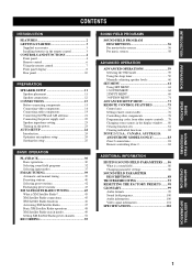
... CONNECTIONS 15 Before connecting components 15 Connecting video components 16 Connecting audio components 19 Connecting the FM and AM antennas 21 Connecting the power supply cord 22 Speaker impedance setting 23 Turning on the power 23 AUTO SETUP 24 Introduction 24 Optimizer microphone setup 24 Starting the setup 25 BASIC OPERATION PLAYBACK 30 Basic operations 30 Selecting sound field programs 32 Selecting input modes 37 FM/AM TUNING 39 Automatic and manual tuning 39 Presetting stations 40 Selecting preset stations 42 Exchanging preset stations 43 XM SATELLITE RADIO TUNING...
... CONNECTIONS 15 Before connecting components 15 Connecting video components 16 Connecting audio components 19 Connecting the FM and AM antennas 21 Connecting the power supply cord 22 Speaker impedance setting 23 Turning on the power 23 AUTO SETUP 24 Introduction 24 Optimizer microphone setup 24 Starting the setup 25 BASIC OPERATION PLAYBACK 30 Basic operations 30 Selecting sound field programs 32 Selecting input modes 37 FM/AM TUNING 39 Automatic and manual tuning 39 Presetting stations 40 Selecting preset stations 42 Exchanging preset stations 43 XM SATELLITE RADIO TUNING...
Owner's Manual
Page 6
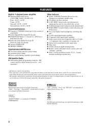
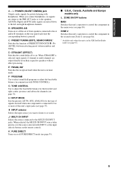
... additional input jacks for discrete multi-channel input ◆ PURE DIRECT for pure fidelity sound with analog and PCM sources ◆ On-screen display function helpful in controlling this unit ◆ S-video signal input/output capability ◆ Component video input/output capability ◆ Video signal conversion (Composite video ↔ S-video → Component video) capability for monitor out ◆ Optical and coaxial digital audio signal jacks ◆ Sleep timer ◆ Cinema and music night listening modes ◆ Remote control with preset remote control codes and "learning...
... additional input jacks for discrete multi-channel input ◆ PURE DIRECT for pure fidelity sound with analog and PCM sources ◆ On-screen display function helpful in controlling this unit ◆ S-video signal input/output capability ◆ Component video input/output capability ◆ Video signal conversion (Composite video ↔ S-video → Component video) capability for monitor out ◆ Optical and coaxial digital audio signal jacks ◆ Sleep timer ◆ Cinema and music night listening modes ◆ Remote control with preset remote control codes and "learning...
Owner's Manual
Page 8
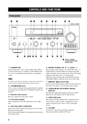
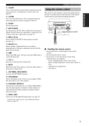
... AUTO/MAN'L MONO DISPLAY PROGRAM INPUT STRAIGHT TONE CONTROL INPUT MODE MULTI CH INPUT PURE DIRECT EFFECT S VIDEO VIDEO AUX VIDEO L AUDIO R OPTICAL A B CD E F G H I JK L (U.S.A., Canada, Australia and Europe models only) 1 STANDBY/ON Turns on this unit, you will hear a click and there will be adjusted when the unit is not in order to receive infrared-signals from the remote control. 2 OPTIMIZER MIC jack Use to connect and input audio signals from a portable external source such as the input source. 0 VOLUME Controls the output level of the speaker channel selected using...
... AUTO/MAN'L MONO DISPLAY PROGRAM INPUT STRAIGHT TONE CONTROL INPUT MODE MULTI CH INPUT PURE DIRECT EFFECT S VIDEO VIDEO AUX VIDEO L AUDIO R OPTICAL A B CD E F G H I JK L (U.S.A., Canada, Australia and Europe models only) 1 STANDBY/ON Turns on this unit, you will hear a click and there will be adjusted when the unit is not in order to receive infrared-signals from the remote control. 2 OPTIMIZER MIC jack Use to connect and input audio signals from a portable external source such as the input source. 0 VOLUME Controls the output level of the speaker channel selected using...
Owner's Manual
Page 9
... speakers connected to select sound field programs or adjust the bass/treble balance (in tuner mode. When STRAIGHT is pressed. INTRODUCTION A PHONES (SILENT CINEMA) jack Outputs audio signals for private listening with TONE CONTROL). C PRESET/TUNING (EDIT), SEARCH MODE* Switches the function of this unit's input jacks (see page 35). F PROGRAM Use to the A and/or B terminals on . ZONE 2 Switches this unit's operation to or watch. B SPEAKERS A/B Turns on or off or on the rear panel each time the corresponding button is selected, input signals (2-channel or multi...
... speakers connected to select sound field programs or adjust the bass/treble balance (in tuner mode. When STRAIGHT is pressed. INTRODUCTION A PHONES (SILENT CINEMA) jack Outputs audio signals for private listening with TONE CONTROL). C PRESET/TUNING (EDIT), SEARCH MODE* Switches the function of this unit's input jacks (see page 35). F PROGRAM Use to the A and/or B terminals on . ZONE 2 Switches this unit's operation to or watch. B SPEAKERS A/B Turns on or off or on the rear panel each time the corresponding button is selected, input signals (2-channel or multi...

Owner's Manual
Page 10
... tuner mode. 8 Cursor buttons u / d / j / i /ENTER Use to select and adjust sound field program parameters or SET MENU items. Press j / i to select a preset station group (A to E) when the unit is sending signals. 3 STANDBY Sets this unit. 5 Input selector buttons Select the input source and change the input source name in tuner mode. to turn on page 75. 1 2 3 4 5 TRANSMIT RE-NAME CLEAR LEARN SYSTEM POWER STANDBY SLEEP INPUT MODE A B PHONO MULTI CH IN V-AUX TUNER MD/CD-R CD DTV/CBL VCR 1 DVR/VCR2 DVD B C D E F G 6 POWER TV REC DISC SKIP SELECT POWER AV AMP AUDIO...
... tuner mode. 8 Cursor buttons u / d / j / i /ENTER Use to select and adjust sound field program parameters or SET MENU items. Press j / i to select a preset station group (A to E) when the unit is sending signals. 3 STANDBY Sets this unit. 5 Input selector buttons Select the input source and change the input source name in tuner mode. to turn on page 75. 1 2 3 4 5 TRANSMIT RE-NAME CLEAR LEARN SYSTEM POWER STANDBY SLEEP INPUT MODE A B PHONO MULTI CH IN V-AUX TUNER MD/CD-R CD DTV/CBL VCR 1 DVR/VCR2 DVD B C D E F G 6 POWER TV REC DISC SKIP SELECT POWER AV AMP AUDIO...
Owner's Manual
Page 11
... the AMP mode to the previous volume level. J VOL +/- O NIGHT, ENT.* Turns on or off or on the main unit during operation. VOLUME OPTIMIZER MIC STANDBY /ON PHONES SPEAKERS A B SILENT CINEMA PRESET/TUNING FM/AM EDIT SEARCH MODE XIM A/B/C/D/E NEXT CATEGORY l PRESET/TUNING/CH h LEVEL MEMORY TUNING MODE MAN'L/AUTO FM AUTO/MAN'L MONO DISPLAY PROGRAM INPUT STRAIGHT TONE CONTROL INPUT MODE MULTI CH INPUT PURE DIRECT EFFECT S VIDEO VIDEO AUX VIDEO L AUDIO R OPTICAL 30 30 TRANSMIT RE-NAME CLEAR LEARN SYSTEM POWER STANDBY SLEEP INPUT MODE PHONO TUNER CD MULTI CH...
... the AMP mode to the previous volume level. J VOL +/- O NIGHT, ENT.* Turns on or off or on the main unit during operation. VOLUME OPTIMIZER MIC STANDBY /ON PHONES SPEAKERS A B SILENT CINEMA PRESET/TUNING FM/AM EDIT SEARCH MODE XIM A/B/C/D/E NEXT CATEGORY l PRESET/TUNING/CH h LEVEL MEMORY TUNING MODE MAN'L/AUTO FM AUTO/MAN'L MONO DISPLAY PROGRAM INPUT STRAIGHT TONE CONTROL INPUT MODE MULTI CH INPUT PURE DIRECT EFFECT S VIDEO VIDEO AUX VIDEO L AUDIO R OPTICAL 30 30 TRANSMIT RE-NAME CLEAR LEARN SYSTEM POWER STANDBY SLEEP INPUT MODE PHONO TUNER CD MULTI CH...
Owner's Manual
Page 12
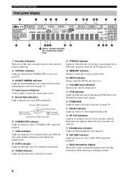
... volume level. E STANDARD Lights up when headphones are selected. G SP A B indicators Light up according to indicate the active DSP sound fields. I HiFi DSP indicator Lights up when both sets of speakers are connected and a sound field program is selected (see page 31). 4 Input source indicators A cursor lights to show that a station can be stored. J Multi-information display Shows the current sound field program name and other information when adjusting or changing settings. 8 B MUTE indicator Flashes while the MUTE function...
... volume level. E STANDARD Lights up when headphones are selected. G SP A B indicators Light up according to indicate the active DSP sound fields. I HiFi DSP indicator Lights up when both sets of speakers are connected and a sound field program is selected (see page 31). 4 Input source indicators A cursor lights to show that a station can be stored. J Multi-information display Shows the current sound field program name and other information when adjusting or changing settings. 8 B MUTE indicator Flashes while the MUTE function...

Owner's Manual
Page 22
... unit using a VIDEO connection, connect your video monitor to this unit using the VIDEO connections. • Converted video signals are only output to OFF. S VIDEO VIDEO AUX VIDEO L AUDIO R OPTICAL S V L R O Optical out Audio out R Audio out L Video out S-video out 18 Game console or video camera When recording, you connect your video source components to this unit if VIDEO CONV. (see page 71) is set to MONITOR OUT jacks. model) DTV/CBL AUDIO VIDEO DTV/ CBL IN VCR 1 OUT COMPONENT VIDEO PR PB Y DTV/ CBL MONITOR OUT Video in Video monitor COAXIAL DIGITAL INPUT...
... unit using a VIDEO connection, connect your video monitor to this unit using the VIDEO connections. • Converted video signals are only output to OFF. S VIDEO VIDEO AUX VIDEO L AUDIO R OPTICAL S V L R O Optical out Audio out R Audio out L Video out S-video out 18 Game console or video camera When recording, you connect your video source components to this unit if VIDEO CONV. (see page 71) is set to MONITOR OUT jacks. model) DTV/CBL AUDIO VIDEO DTV/ CBL IN VCR 1 OUT COMPONENT VIDEO PR PB Y DTV/ CBL MONITOR OUT Video in Video monitor COAXIAL DIGITAL INPUT...
Owner's Manual
Page 28
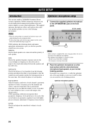
... microphone setup 1 Connect the supplied optimizer microphone to improve the sound relationship between the speakers and the subwoofer. model) OPTIMIZER MIC STANDBY /ON PHONES SPEAKERS A B SILENT CINEMA PRESET/TUNING FM/AM EDIT SEARCH MODE XIM A/B/C/D/E NEXT CATEGORY l PRESET/TUNING/CH h LEVEL PROGRAM STRAIGHT TONE CONTROL INPUT MODE EFFECT Notes • After you the best possible sound from the listening position and adjusts the delay of each speaker. 24 Do not place it away from each speaker. If possible, use different...
... microphone setup 1 Connect the supplied optimizer microphone to improve the sound relationship between the speakers and the subwoofer. model) OPTIMIZER MIC STANDBY /ON PHONES SPEAKERS A B SILENT CINEMA PRESET/TUNING FM/AM EDIT SEARCH MODE XIM A/B/C/D/E NEXT CATEGORY l PRESET/TUNING/CH h LEVEL PROGRAM STRAIGHT TONE CONTROL INPUT MODE EFFECT Notes • After you the best possible sound from the listening position and adjusts the delay of each speaker. 24 Do not place it away from each speaker. If possible, use different...

Owner's Manual
Page 37
... Dolby Digital signals in 6.1/ 7.1 channels. EX For playing back Dolby Digital or DTS signals in the front panel display. CH RETURN MEMORY STEREO 1 TV VOL ON SCREEN STRAIGHT DISPLAY EFFECT MUSIC ENTERTAIN MOVIE 2 3 4 STANDARD SELECT EXTD SUR. BASIC OPERATION ■ Remote control operation TRANSMIT RE-NAME CLEAR LEARN SYSTEM POWER STANDBY SLEEP INPUT MODE A B PHONO MULTI CH IN V-AUX TUNER MD/CD-R CD DTV/CBL VCR 1 DVR/VCR2 DVD AMP POWER TV REC SELECT POWER AV AMP AUDIO LEVEL TITLE BAND TV INPUT CH PRESET/CH TV VOL SET MENU MENU...
... Dolby Digital signals in 6.1/ 7.1 channels. EX For playing back Dolby Digital or DTS signals in the front panel display. CH RETURN MEMORY STEREO 1 TV VOL ON SCREEN STRAIGHT DISPLAY EFFECT MUSIC ENTERTAIN MOVIE 2 3 4 STANDARD SELECT EXTD SUR. BASIC OPERATION ■ Remote control operation TRANSMIT RE-NAME CLEAR LEARN SYSTEM POWER STANDBY SLEEP INPUT MODE A B PHONO MULTI CH IN V-AUX TUNER MD/CD-R CD DTV/CBL VCR 1 DVR/VCR2 DVD AMP POWER TV REC SELECT POWER AV AMP AUDIO LEVEL TITLE BAND TV INPUT CH PRESET/CH TV VOL SET MENU MENU...

Owner's Manual
Page 63
... POWER STANDBY SLEEP INPUT MODE A B PHONO MULTI CH IN V-AUX TUNER MD/CD-R CD DTV/CBL VCR 1 DVR/VCR2 DVD 2 POWER TV SELECT POWER AV AMP 1 Select a source and start playback on the video monitor connected to this information on the front panel display. 1 Turn on the source component. 2 Press SLEEP repeatedly to set the amount of time. The SLEEP indicator flashes while switching the amount of the screen each time you are displayed. If you press SLEEP, the front panel display changes...
... POWER STANDBY SLEEP INPUT MODE A B PHONO MULTI CH IN V-AUX TUNER MD/CD-R CD DTV/CBL VCR 1 DVR/VCR2 DVD 2 POWER TV SELECT POWER AV AMP 1 Select a source and start playback on the video monitor connected to this information on the front panel display. 1 Turn on the source component. 2 Press SLEEP repeatedly to set the amount of time. The SLEEP indicator flashes while switching the amount of the screen each time you are displayed. If you press SLEEP, the front panel display changes...

Owner's Manual
Page 64
... speaker level Surround right speaker level Surround left speaker level Surround back right speaker level Surround back left speaker level Subwoofer level Presence left speaker level Presence right speaker level y Once you press LEVEL, you have completed your adjustment. Manually adjusting speaker levels You can also select the speaker by pressing STANDBY on the remote control (or STANDBY/ON on the front panel. Please note that this unit to a music source. POWER TV REC DISC SKIP POWER AV AMP AUDIO VOL 1 2 LEVEL TITLE BAND TV INPUT CH PRESET/CH TV VOL SET MENU MENU SRCH MODE...
... speaker level Surround right speaker level Surround left speaker level Surround back right speaker level Surround back left speaker level Subwoofer level Presence left speaker level Presence right speaker level y Once you press LEVEL, you have completed your adjustment. Manually adjusting speaker levels You can also select the speaker by pressing STANDBY on the remote control (or STANDBY/ON on the front panel. Please note that this unit to a music source. POWER TV REC DISC SKIP POWER AV AMP AUDIO VOL 1 2 LEVEL TITLE BAND TV INPUT CH PRESET/CH TV VOL SET MENU MENU SRCH MODE...
Owner's Manual
Page 65
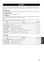
...center speaker. 67 E)LFE LEVEL Adjusts the output level of the LFE channel for Dolby Digital or DTS signals. 68 F)DYNAMIC RANGE Adjusts the dynamic range for Dolby Digital or DTS signals. 68 G)AUDIO SET Customizes the muting level, audio delay and tone bypass settings. 68 2 INPUT MENU Use to reassign digital input/outputs, select the input mode or rename your listening environment. ■ AUTO SETUP Use to specify which speaker parameters auto setup will adjust, and to activate the auto setup procedure (see page 24). You can use SOUND MENU to manually adjust any speaker setting...
...center speaker. 67 E)LFE LEVEL Adjusts the output level of the LFE channel for Dolby Digital or DTS signals. 68 F)DYNAMIC RANGE Adjusts the dynamic range for Dolby Digital or DTS signals. 68 G)AUDIO SET Customizes the muting level, audio delay and tone bypass settings. 68 2 INPUT MENU Use to reassign digital input/outputs, select the input mode or rename your listening environment. ■ AUTO SETUP Use to specify which speaker parameters auto setup will adjust, and to activate the auto setup procedure (see page 24). You can use SOUND MENU to manually adjust any speaker setting...
Owner's Manual
Page 68
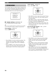
... front channel to manually adjust any speaker setting or compensate for video signal processing delays when using LCD monitors or projectors. This will set the unit to the front left and right speakers. L/R SP Choices: LRG, SML, NONE SUR. The unit directs the low-frequency signals of the center channel signal to the Virtual CINEMA DSP mode (see page 24). Front speakers FRONT SP Choices: LARGE, SMALL FRONT SP NONE )SML LRG • Select...
... front channel to manually adjust any speaker setting or compensate for video signal processing delays when using LCD monitors or projectors. This will set the unit to the front left and right speakers. L/R SP Choices: LRG, SML, NONE SUR. The unit directs the low-frequency signals of the center channel signal to the Virtual CINEMA DSP mode (see page 24). Front speakers FRONT SP Choices: LARGE, SMALL FRONT SP NONE )SML LRG • Select...

Owner's Manual
Page 72
... effective only when this units overall audio settings. SET MENU ■ Low-frequency effect level E)LFE LEVEL Use to adjust the output level of the LFE (low-frequency effect) channel according to delay the sound output and synchronize it with the video image. The LFE channel carries lowfrequency special effects which are set to certain scenes. SPEAKER;;;;;;0dB HEADPHONE;;;;0dB [ ]/[ ]:Up/Down []:Adjust Speaker SPEAKER Select to adjust how much the mute function reduces the output volume. Choices: MIN (minimum), STD (standard), MAX...
... effective only when this units overall audio settings. SET MENU ■ Low-frequency effect level E)LFE LEVEL Use to adjust the output level of the LFE (low-frequency effect) channel according to delay the sound output and synchronize it with the video image. The LFE channel carries lowfrequency special effects which are set to certain scenes. SPEAKER;;;;;;0dB HEADPHONE;;;;0dB [ ]/[ ]:Up/Down []:Adjust Speaker SPEAKER Select to adjust how much the mute function reduces the output volume. Choices: MIN (minimum), STD (standard), MAX...
Owner's Manual
Page 79
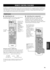
... by setting appropriate remote control codes (see page 76). A:DVD Fixed AMP mode DVD Component control mode To temporarily switch to another component without changing the input source on the selected component. Each button has a different function depending on this unit. The name of the selected component appears in AMP mode. Factory setting: A...LD player B...CD recorder SELECT k/n switches control to component control mode, press AMP. LEVEL TITLE BAND TV INPUT CH PRESET/CH TV VOL SET MENU MENU SRCH MODE MUTE TV MUTE ENTER A-E/CAT. CH RETURN MEMORY STEREO 1 TV...
... by setting appropriate remote control codes (see page 76). A:DVD Fixed AMP mode DVD Component control mode To temporarily switch to another component without changing the input source on the selected component. Each button has a different function depending on this unit. The name of the selected component appears in AMP mode. Factory setting: A...LD player B...CD recorder SELECT k/n switches control to component control mode, press AMP. LEVEL TITLE BAND TV INPUT CH PRESET/CH TV VOL SET MENU MENU SRCH MODE MUTE TV MUTE ENTER A-E/CAT. CH RETURN MEMORY STEREO 1 TV...
Owner's Manual
Page 89
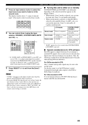
... in the Zone 2 mode. ZONE 2 (U.S.A., CANADA, AUSTRALIA AND EUROPE MODELS ONLY) 3 Press an input selector button to select the input source you want to listen to in DTS Only 2 channel analog audio signals may damage your speakers). To exit Zone 3 mode, press SELECT n. • Since the Zone 2 code is common to "ID1Z" and "ID2Z", the Zone 2 code does not change even if the AMP library code (remote control setting) is set the DVD player's mixed 2-channel left and right audio outputs to Zone 3 mode. For DVDs encoded...
... in the Zone 2 mode. ZONE 2 (U.S.A., CANADA, AUSTRALIA AND EUROPE MODELS ONLY) 3 Press an input selector button to select the input source you want to listen to in DTS Only 2 channel analog audio signals may damage your speakers). To exit Zone 3 mode, press SELECT n. • Since the Zone 2 code is common to "ID1Z" and "ID2Z", the Zone 2 code does not change even if the AMP library code (remote control setting) is set the DVD player's mixed 2-channel left and right audio outputs to Zone 3 mode. For DVDs encoded...
Owner's Manual
Page 97
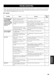
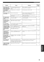
... -screen display is currently being received from a source component, such as lightning or strong static electricity). The optimizer microphone is turned down. Speaker connections are being received. Select AUTO. Refer to AUTO or DTS. The volume is connected. The output and input for each connection does not touch anything other than its respective connection. Remedy Connect the power cord firmly. Signals this unit to the standby mode, disconnect the power cord, and contact the nearest authorized YAMAHA dealer or service center...
... -screen display is currently being received from a source component, such as lightning or strong static electricity). The optimizer microphone is turned down. Speaker connections are being received. Select AUTO. Refer to AUTO or DTS. The volume is connected. The output and input for each connection does not touch anything other than its respective connection. Remedy Connect the power cord firmly. Signals this unit to the standby mode, disconnect the power cord, and contact the nearest authorized YAMAHA dealer or service center...
Owner's Manual
Page 99
... panel display. operate properly. "CHECK SP WIRES" appears in SET MENU is distorted. Make sure all speaker cables are short circuited. A source cannot be output Dolby Digital or DTS digital instructions for your turnable to AUTO or DTS. 37 display does not light up.) A "humming" sound Incorrect cable connections. sources cannot be recorded by an analog component connected to the AUDIO OUT jacks. GND terminal of this unit's analog AUDIO IN jacks. The volume level The component connected to the OUT Turn on the front panel The input mode...
... panel display. operate properly. "CHECK SP WIRES" appears in SET MENU is distorted. Make sure all speaker cables are short circuited. A source cannot be output Dolby Digital or DTS digital instructions for your turnable to AUTO or DTS. 37 display does not light up.) A "humming" sound Incorrect cable connections. sources cannot be recorded by an analog component connected to the AUDIO OUT jacks. GND terminal of this unit's analog AUDIO IN jacks. The volume level The component connected to the OUT Turn on the front panel The input mode...


