
Owner's Manual
Page 3
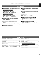
...REMOTE CONTROL TRANSMITTER 5 CONNECTIONS 6 CONTROLS AND THEIR FUNCTIONS ........10 RECEIVING RDS STATIONS RX-496RDS and RX-396RDS only .........21 TROUBLESHOOTING 26 SPECIFICATIONS 27 3 FEATURES q Minimum RMS Output Power per Channel RX-496RDS and RX-496 75W + 75W (8Ω) RMS Output Power, 0.04% THD, 20-20,000 Hz RX-396RDS and RX-396... Preset Tuning q Preset Station Shifting Capability (Preset Editing) q IF Count Direct PLL Synthesizer Tuning System q SLEEP Timer q Remote Control Capability q RX-496RDS and RX-396RDS only Multi-Functions for selecting this YAMAHA Stereo receiver.
...REMOTE CONTROL TRANSMITTER 5 CONNECTIONS 6 CONTROLS AND THEIR FUNCTIONS ........10 RECEIVING RDS STATIONS RX-496RDS and RX-396RDS only .........21 TROUBLESHOOTING 26 SPECIFICATIONS 27 3 FEATURES q Minimum RMS Output Power per Channel RX-496RDS and RX-496 75W + 75W (8Ω) RMS Output Power, 0.04% THD, 20-20,000 Hz RX-396RDS and RX-396... Preset Tuning q Preset Station Shifting Capability (Preset Editing) q IF Count Direct PLL Synthesizer Tuning System q SLEEP Timer q Remote Control Capability q RX-496RDS and RX-396RDS only Multi-Functions for selecting this YAMAHA Stereo receiver.
Owner's Manual
Page 5
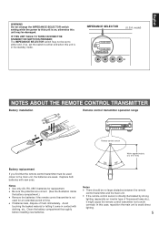
.... q Be sure the polarities are weak. q If batteries leak, dispose of time. The IMPEDANCE SELECTOR switch may be damaged. q If the remote control sensor is in contact with new ones. Replace both batteries with clothing, etc. Avoid touching the leaked material or letting it might cause the... the switch to the main unit, the batteries are correct. (See the illustration inside the battery compartment.) q Remove the batteries if the remote control transmitter is on, otherwise this case, reposition the main unit to work correctly. If so, set to this unit is not used ...
.... q Be sure the polarities are weak. q If batteries leak, dispose of time. The IMPEDANCE SELECTOR switch may be damaged. q If the remote control sensor is in contact with new ones. Replace both batteries with clothing, etc. Avoid touching the leaked material or letting it might cause the... the switch to the main unit, the batteries are correct. (See the illustration inside the battery compartment.) q Remove the batteries if the remote control transmitter is on, otherwise this case, reposition the main unit to work correctly. If so, set to this unit is not used ...
Owner's Manual
Page 6
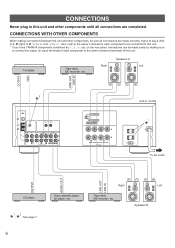
on the rear panel, connections can be connected to this unit. * If you have YAMAHA components numbered as 1, 3, 4, etc. SPEAKERS (U.S.A. Also, refer to the owner's manual for each component to "-". TOTAL SWITCHED AC OUTLETS To AC outlet OUTPUT AUDIO... all connections are made easily by making connections between this unit and other components until all connections are completed. FM ANT GND AM ANT GND REMOTE CONTROL IN OUT PHONO CD AUX TAPE 1 PLAY /MD REC TAPE 2 PLAY REC 1 3 4 3 or 5 4 or 6 AUDIO SIGNAL A OR B:4ΩMIN. /SPEAKER A B:8ΩMIN. /SPEAKER ...
on the rear panel, connections can be connected to this unit. * If you have YAMAHA components numbered as 1, 3, 4, etc. SPEAKERS (U.S.A. Also, refer to the owner's manual for each component to "-". TOTAL SWITCHED AC OUTLETS To AC outlet OUTPUT AUDIO... all connections are made easily by making connections between this unit and other components until all connections are completed. FM ANT GND AM ANT GND REMOTE CONTROL IN OUT PHONO CD AUX TAPE 1 PLAY /MD REC TAPE 2 PLAY REC 1 3 4 3 or 5 4 or 6 AUDIO SIGNAL A OR B:4ΩMIN. /SPEAKER A B:8ΩMIN. /SPEAKER ...

Owner's Manual
Page 7
... this unit is 100 watts. 2 *GND terminal (For turntable use only one speaker system, connect it to this unit's STANDBY/ON switch or the provided remote control transmitter's STANDBY/ON key. Use speakers with wire of components) that can be unnatural and lack bass. The power to any metal part of...
... this unit is 100 watts. 2 *GND terminal (For turntable use only one speaker system, connect it to this unit's STANDBY/ON switch or the provided remote control transmitter's STANDBY/ON key. Use speakers with wire of components) that can be unnatural and lack bass. The power to any metal part of...
Owner's Manual
Page 8
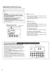
... the impedance of each speaker must be 8Ω or higher. (Right position) If you can also operate the component with the system remote control. If you use two pairs of speakers, the impedance of the central controller for custom installation system. The impedance of each speaker ...must be 12Ω or higher. GND REMOTE CONTROL IN OUT PHONO CD AUX TAPE 1 PLAY /MD REC TAPE 2 PLAY REC 1 3 4 3 or 5 4 or 6 AUDIO SIGNAL 8 Select the position ...
... the impedance of each speaker must be 8Ω or higher. (Right position) If you can also operate the component with the system remote control. If you use two pairs of speakers, the impedance of the central controller for custom installation system. The impedance of each speaker ...must be 12Ω or higher. GND REMOTE CONTROL IN OUT PHONO CD AUX TAPE 1 PLAY /MD REC TAPE 2 PLAY REC 1 3 4 3 or 5 4 or 6 AUDIO SIGNAL 8 Select the position ...
Owner's Manual
Page 11
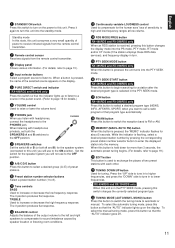
... controls BASS Used to increase or decrease the high frequency response. The 0 position produces flat response. D RDS MODE/FREQ button RX-496RDS and RX-396RDS only When an RDS station is received, pressing this button to select a desired group (A-E) of preset stations. 0 Preset ...Press it again to turn this unit consumes a very small quantity of power to receive infrared-signals from the remote control transmitter. 2 Remote control sensor Receives signals from the remote control transmitter. 3 Display panel Shows various information. (For details, refer to page 13.) 4 Input selector ...
... controls BASS Used to increase or decrease the high frequency response. The 0 position produces flat response. D RDS MODE/FREQ button RX-496RDS and RX-396RDS only When an RDS station is received, pressing this button to select a desired group (A-E) of preset stations. 0 Preset ...Press it again to turn this unit consumes a very small quantity of power to receive infrared-signals from the remote control transmitter. 2 Remote control sensor Receives signals from the remote control transmitter. 3 Display panel Shows various information. (For details, refer to page 13.) 4 Input selector ...
Owner's Manual
Page 12
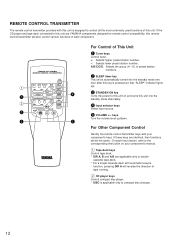
... E) of each key function, refer to the corresponding instruction on and turns this remote control transmitter will be the same. If these keys are YAMAHA components designed for remote control compatibility, this unit into the standby mode one hour after this key is pressed.... PRESET + A/B/C/D/E TUNER DISC PLAY CD PHONO STANDBY/ON SLEEP VOLUME 4 5 For Control of this unit. On each component. 1 1 2 2 3 YAMAHA HiFi SYSTEM REMOTE CONTROL TRANSMITTER AUX DIR A DIR B REC/PAUSE PLAY TAPE 2 A/B TAPE 1 - A/B/C/D/E: Selects the group (A - If the CD player and tape deck...
... E) of each key function, refer to the corresponding instruction on and turns this remote control transmitter will be the same. If these keys are YAMAHA components designed for remote control compatibility, this unit into the standby mode one hour after this key is pressed.... PRESET + A/B/C/D/E TUNER DISC PLAY CD PHONO STANDBY/ON SLEEP VOLUME 4 5 For Control of this unit. On each component. 1 1 2 2 3 YAMAHA HiFi SYSTEM REMOTE CONTROL TRANSMITTER AUX DIR A DIR B REC/PAUSE PLAY TAPE 2 A/B TAPE 1 - A/B/C/D/E: Selects the group (A - If the CD player and tape deck...
Owner's Manual
Page 14
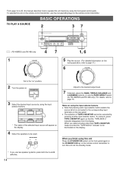
...TAPE 2 MONITOR, make sure that the "TAPE MON 2" indicator is connected to the corresponding input terminals on the remote control transmitter, use the PURE DIRECT switch (for RX-496RDS and RX-496 only). From page 14 to 25, this manual describes how to operate this unit mainly by using the input... selector buttons. To operate this unit on the rear panel. SPEAKERS A B ON OFF 5 Play the source. (For detailed information on the remote control transmitter. ...
...TAPE 2 MONITOR, make sure that the "TAPE MON 2" indicator is connected to the corresponding input terminals on the remote control transmitter, use the PURE DIRECT switch (for RX-496RDS and RX-496 only). From page 14 to 25, this manual describes how to operate this unit mainly by using the input... selector buttons. To operate this unit on the rear panel. SPEAKERS A B ON OFF 5 Play the source. (For detailed information on the remote control transmitter. ...
Owner's Manual
Page 26
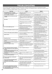
...Only one side speaker outputs the sound. There are connected in the SYMPTOM column, disconnect the power cord and contact your authorized YAMAHA dealer or service center for a long period. CAUSE Power cord is difficult to eliminate all the noises. The SPEAKERS switches are ... There is a lack of this unit. The SLEEP timer has functioned. A desired station cannot be obtained even with new ones. The remote control transmitter does not work normally. Speaker connections are too weak. Adjust antenna placement to either end. Use an outdoor antenna and a ...
...Only one side speaker outputs the sound. There are connected in the SYMPTOM column, disconnect the power cord and contact your authorized YAMAHA dealer or service center for a long period. CAUSE Power cord is difficult to eliminate all the noises. The SPEAKERS switches are ... There is a lack of this unit. The SLEEP timer has functioned. A desired station cannot be obtained even with new ones. The remote control transmitter does not work normally. Speaker connections are too weak. Adjust antenna placement to either end. Use an outdoor antenna and a ...


