
Owner's Manual
Page 3
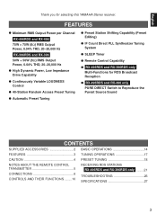
...REMOTE CONTROL TRANSMITTER 5 CONNECTIONS 6 CONTROLS AND THEIR FUNCTIONS ........10 RECEIVING RDS STATIONS RX-496RDS and RX-396RDS only .........21 TROUBLESHOOTING 26 SPECIFICATIONS 27 3 FEATURES q Minimum RMS Output Power per Channel RX-496RDS and RX-496 75W + 75W (8Ω) RMS Output Power, 0.04% THD, 20-20,000 Hz RX-396RDS and RX-396... Preset Tuning q Preset Station Shifting Capability (Preset Editing) q IF Count Direct PLL Synthesizer Tuning System q SLEEP Timer q Remote Control Capability q RX-496RDS and RX-396RDS only Multi-Functions for selecting this YAMAHA Stereo receiver.
...REMOTE CONTROL TRANSMITTER 5 CONNECTIONS 6 CONTROLS AND THEIR FUNCTIONS ........10 RECEIVING RDS STATIONS RX-496RDS and RX-396RDS only .........21 TROUBLESHOOTING 26 SPECIFICATIONS 27 3 FEATURES q Minimum RMS Output Power per Channel RX-496RDS and RX-496 75W + 75W (8Ω) RMS Output Power, 0.04% THD, 20-20,000 Hz RX-396RDS and RX-396... Preset Tuning q Preset Station Shifting Capability (Preset Editing) q IF Count Direct PLL Synthesizer Tuning System q SLEEP Timer q Remote Control Capability q RX-496RDS and RX-396RDS only Multi-Functions for selecting this YAMAHA Stereo receiver.
Owner's Manual
Page 5
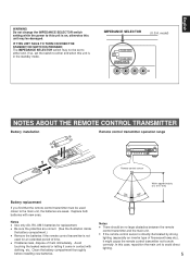
... the main unit, the batteries are correct. (See the illustration inside the battery compartment.) q Remove the batteries if the remote control transmitter is directly illuminated by strong lighting (especially an inverter type of fluorescent lamp etc.), it come in the standby ...mode. IMPEDANCE SELECTOR (U.S.A. Avoid touching the leaked material or letting it might cause the remote control transmitter not to avoid direct lighting. 5 model) A OR B:4ΩMIN. /SPEAKER A B:8ΩMIN. /SPEAKER A OR B: 6ΩMIN....
... the main unit, the batteries are correct. (See the illustration inside the battery compartment.) q Remove the batteries if the remote control transmitter is directly illuminated by strong lighting (especially an inverter type of fluorescent lamp etc.), it come in the standby ...mode. IMPEDANCE SELECTOR (U.S.A. Avoid touching the leaked material or letting it might cause the remote control transmitter not to avoid direct lighting. 5 model) A OR B:4ΩMIN. /SPEAKER A B:8ΩMIN. /SPEAKER A OR B: 6ΩMIN....
Owner's Manual
Page 6
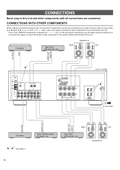
...L, R (right) to R, "+" to "+" and "-" to be sure all connections are made easily by making connections between this unit. * If you have YAMAHA components numbered as 1, 3, 4, etc. Turntable Tape deck, MD recorder, etc. SPEAKERS (U.S.A. Left Speakers B Also, refer to the owner's manual for each ... of this unit and other components, be connected to this unit and other components until all connections are completed. FM ANT GND AM ANT GND REMOTE CONTROL IN OUT PHONO CD AUX TAPE 1 PLAY /MD REC TAPE 2 PLAY REC 1 3 4 3 or 5 4 or 6 AUDIO SIGNAL A OR B:4Ω...
...L, R (right) to R, "+" to "+" and "-" to be sure all connections are made easily by making connections between this unit. * If you have YAMAHA components numbered as 1, 3, 4, etc. Turntable Tape deck, MD recorder, etc. SPEAKERS (U.S.A. Left Speakers B Also, refer to the owner's manual for each ... of this unit and other components, be connected to this unit and other components until all connections are completed. FM ANT GND AM ANT GND REMOTE CONTROL IN OUT PHONO CD AUX TAPE 1 PLAY /MD REC TAPE 2 PLAY REC 1 3 4 3 or 5 4 or 6 AUDIO SIGNAL A OR B:4Ω...

Owner's Manual
Page 7
... part of this unit is the + and - If these to the SWITCHED AC OUTLETS is controlled by this unit's STANDBY/ON switch or the provided remote control transmitter's STANDBY/ON key. Note One or two speaker systems can be heard from your speakers with the specified impedance shown on . The maximum...
... part of this unit is the + and - If these to the SWITCHED AC OUTLETS is controlled by this unit's STANDBY/ON switch or the provided remote control transmitter's STANDBY/ON key. Note One or two speaker systems can be heard from your speakers with the specified impedance shown on . The maximum...
Owner's Manual
Page 8
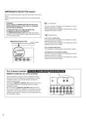
...8486; or higher. If you use two pairs of speakers, the impedance of each speaker must be 8Ω or higher. By connecting the REMOTE CONTROL OUT terminal of this unit is not on , otherwise this way, up to 6 components can operate this unit is connected to the components...Ω or higher. When this unit is in series. Select the position whose requirements your speaker system meets. Connect the REMOTE CONTROL IN terminal of this unit to either end. GND REMOTE CONTROL IN OUT PHONO CD AUX TAPE 1 PLAY /MD REC TAPE 2 PLAY REC 1 3 4 3 or 5 4 or 6 AUDIO SIGNAL...
...8486; or higher. If you use two pairs of speakers, the impedance of each speaker must be 8Ω or higher. By connecting the REMOTE CONTROL OUT terminal of this unit is not on , otherwise this way, up to 6 components can operate this unit is connected to the components...Ω or higher. When this unit is in series. Select the position whose requirements your speaker system meets. Connect the REMOTE CONTROL IN terminal of this unit to either end. GND REMOTE CONTROL IN OUT PHONO CD AUX TAPE 1 PLAY /MD REC TAPE 2 PLAY REC 1 3 4 3 or 5 4 or 6 AUDIO SIGNAL...
Owner's Manual
Page 11
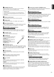
...purest sound. (Refer to page 16 for the human ears' loss of power to receive infrared-signals from the remote control transmitter. 2 Remote control sensor Receives signals from the remote control transmitter. 3 Display panel Shows various information. (For details, refer to page 13.) 4 Input selector ...buttons Select a program source to listen to high and low-frequency ranges at low volume. F PTY SEEK START button RX-496RDS and RX-396RDS only Press...
...purest sound. (Refer to page 16 for the human ears' loss of power to receive infrared-signals from the remote control transmitter. 2 Remote control sensor Receives signals from the remote control transmitter. 3 Display panel Shows various information. (For details, refer to page 13.) 4 Input selector ...buttons Select a program source to listen to high and low-frequency ranges at low volume. F PTY SEEK START button RX-496RDS and RX-396RDS only Press...
Owner's Manual
Page 12
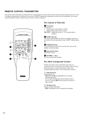
... power to this unit on your component's keys. If the CD player and tape deck connected to this unit are YAMAHA components designed for remote control compatibility, this unit. If these keys are applicable only to double cassette tape deck. * For a single cassette...E) of This Unit 1 Tuner keys Control tuner. +: Selects higher preset station number. -: Selects lower preset station number. For Other Component Control Identify the remote control transmitter keys with your component's manual. 1 Tape deck keys Control tape deck. * DIR A, B and A/B are identical, their functions will be ...
... power to this unit on your component's keys. If the CD player and tape deck connected to this unit are YAMAHA components designed for remote control compatibility, this unit. If these keys are applicable only to double cassette tape deck. * For a single cassette...E) of This Unit 1 Tuner keys Control tuner. +: Selects higher preset station number. -: Selects lower preset station number. For Other Component Control Identify the remote control transmitter keys with your component's manual. 1 Tape deck keys Control tape deck. * DIR A, B and A/B are identical, their functions will be ...
Owner's Manual
Page 14
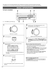
... appear on the display. Notes on using the front panel control parts. SPEAKERS A B ON OFF 5 Play the source. (For detailed information on the remote control transmitter. When you use two speaker systems, press both the A and B switches. 14 From page 14 to 25, this manual describes how to... the STANDBY/ON switch on the front panel again or the STANDBY/ON key on the remote control transmitter to turn this unit on the remote control transmitter, use the PURE DIRECT switch (for RX-496RDS and RX-496 only). To cancel it, press TAPE 2 MONITOR again so that the "TAPE MON...
... appear on the display. Notes on using the front panel control parts. SPEAKERS A B ON OFF 5 Play the source. (For detailed information on the remote control transmitter. When you use two speaker systems, press both the A and B switches. 14 From page 14 to 25, this manual describes how to... the STANDBY/ON switch on the front panel again or the STANDBY/ON key on the remote control transmitter to turn this unit on the remote control transmitter, use the PURE DIRECT switch (for RX-496RDS and RX-496 only). To cancel it, press TAPE 2 MONITOR again so that the "TAPE MON...
Owner's Manual
Page 26
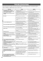
... work . A desired station cannot be used nearby. The sound is connected with the headphones connected to either end. There is striking the remote control sensor of the main unit. The protection circuit has been activated because of strong external noise (lightning, excessive static electricity, etc.) or... input source with new ones. Adjust it cannot be tuned in the SYMPTOM column, disconnect the power cord and contact your authorized YAMAHA dealer or service center for help somewhat but it for a long period. Turn the power to reset the protection circuit. Set the...
... work . A desired station cannot be used nearby. The sound is connected with the headphones connected to either end. There is striking the remote control sensor of the main unit. The protection circuit has been activated because of strong external noise (lightning, excessive static electricity, etc.) or... input source with new ones. Adjust it cannot be tuned in the SYMPTOM column, disconnect the power cord and contact your authorized YAMAHA dealer or service center for help somewhat but it for a long period. Turn the power to reset the protection circuit. Set the...


