
Owner's Manual
Page 7
...switch scenes ...122 Using GPI (General Purpose Interface 123 Using GPI IN 123 Calibrating the GPI IN ports 125 Using GPI OUT 126 17 Using memory cards 128 Using memory cards with the PM5D 128 Saving files to a memory card 128 Loading files from a memory ...the PM5D to a computer via USB ..........146 Caution when using the USB TO HOST connector ........ 146 Initializing the PM5D's internal memory 147 Adjusting the faders and input/output gain (Calibration 147 Calibrating the faders 148 Adjusting the analog input gain (PM5D-RH model only 148 Adjusting the output gain 148 PM5D/PM5D-RH...
...switch scenes ...122 Using GPI (General Purpose Interface 123 Using GPI IN 123 Calibrating the GPI IN ports 125 Using GPI OUT 126 17 Using memory cards 128 Using memory cards with the PM5D 128 Saving files to a memory card 128 Loading files from a memory ...the PM5D to a computer via USB ..........146 Caution when using the USB TO HOST connector ........ 146 Initializing the PM5D's internal memory 147 Adjusting the faders and input/output gain (Calibration 147 Calibrating the faders 148 Adjusting the analog input gain (PM5D-RH model only 148 Adjusting the output gain 148 PM5D/PM5D-RH...
Owner's Manual
Page 147
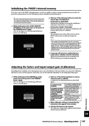
...ENTER] key of the panel, turn on the power of the motor faders. A window for the calibration item you selected will appear, allowing you can use , discrepancies may occur in the behavior of the PW800W power supply. PM5D-RH model only) The AD INPUT TRIM window will be lost if... you to make fine adjustments to calibrate the specified faders. The calibration settings will appear, allowing you initialize the internal memory.
...ENTER] key of the panel, turn on the power of the motor faders. A window for the calibration item you selected will appear, allowing you can use , discrepancies may occur in the behavior of the PW800W power supply. PM5D-RH model only) The AD INPUT TRIM window will be lost if... you to make fine adjustments to calibrate the specified faders. The calibration settings will appear, allowing you initialize the internal memory.
Owner's Manual
Page 148
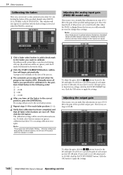
... to 0.00 dB, click the FACTORY PRESET button. calibration will also appear if a problem with certain faders were detected during start-up . do not turn off . Click the OK button to apply the settings. 148 PM5D/PM5D-RH Owner's Manual Operating section Click the OK button... to apply the settings. Note Since these settings. The calibration settings will proceed to the next fader position. 5 Repeat steps 3-4 for calibration to the positions listed below in steps of...
... to 0.00 dB, click the FACTORY PRESET button. calibration will also appear if a problem with certain faders were detected during start-up . do not turn off . Click the OK button to apply the settings. 148 PM5D/PM5D-RH Owner's Manual Operating section Click the OK button... to apply the settings. Note Since these settings. The calibration settings will proceed to the next fader position. 5 Repeat steps 3-4 for calibration to the positions listed below in steps of...
Owner's Manual
Page 178
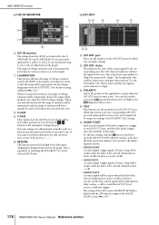
...to switching the POLARITY (3) of voltage variation used by a yellow in the X-axis (horizontal) and Y-axis (vertical) dimensions of the FADER START screen (➥ p.179). 178 PM5D/PM5D-RH Owner's Manual Reference section You can make settings. MIDI REMOTE function ❏ GPI IN MONITOR 8 6 9 7 J F ... XAXIS field (8) and Y-AXIS field (9) is respectively indicated by the PM5D to determine active/inactive status, so that is output when the GPI OUT port becomes active. G CALIBRATION This button calibrates the range of voltage variation used to determine the active/inactive state. ...
...to switching the POLARITY (3) of voltage variation used by a yellow in the X-axis (horizontal) and Y-axis (vertical) dimensions of the FADER START screen (➥ p.179). 178 PM5D/PM5D-RH Owner's Manual Reference section You can make settings. MIDI REMOTE function ❏ GPI IN MONITOR 8 6 9 7 J F ... XAXIS field (8) and Y-AXIS field (9) is respectively indicated by the PM5D to determine active/inactive status, so that is output when the GPI OUT port becomes active. G CALIBRATION This button calibrates the range of voltage variation used to determine the active/inactive state. ...
Owner's Manual
Page 359
...External user interface 21 F Fade function 87 FADE TIME 87, 167 FADER ASSIGN 197 Fader Assign function 139 Fader calibration 147 FADER FLIP/ENCODER MODE section 40 FADER MODE 150, 151 FADER MODE section 139 FADER START 179 FADER VIEW 249, 288 Faders 19, 25 FADING indicator 150 Features 10 FIX ASSIGN VIEW 282 ... INPUT PATCH LIBRARY...... 257 INSERT PATCH 254 INSERT/DIRECT OUT POINT 256 NAME 257 INPUT SOLO SAFE 219 PM5D/PM5D-RH Owner's Manual Reference section 359 Appendices Input functions Output functions Global functions Function menu Information shown in the display
...External user interface 21 F Fade function 87 FADE TIME 87, 167 FADER ASSIGN 197 Fader Assign function 139 Fader calibration 147 FADER FLIP/ENCODER MODE section 40 FADER MODE 150, 151 FADER MODE section 139 FADER START 179 FADER VIEW 249, 288 Faders 19, 25 FADING indicator 150 Features 10 FIX ASSIGN VIEW 282 ... INPUT PATCH LIBRARY...... 257 INSERT PATCH 254 INSERT/DIRECT OUT POINT 256 NAME 257 INPUT SOLO SAFE 219 PM5D/PM5D-RH Owner's Manual Reference section 359 Appendices Input functions Output functions Global functions Function menu Information shown in the display


