

Owner's Manual
Page 2
...Read these instructions. 2 Keep these requirements provides a reasonable level of interference, which can not locate the appropriate retailer, please contact Yamaha Corporation of America, Electronic Service Division, 6600 Orangethorpe Ave, Buena Park, CA90620 The above warning is required when the apparatus has ... two blades with this apparatus near any ventilation openings. IMPORTANT NOTICE: DO NOT MODIFY THIS UNIT! This product, when installed as power-supply cord or plug is found to comply with these instructions. 3 Heed all warnings. 4 Follow all servicing to co-axial type ...
...Read these instructions. 2 Keep these requirements provides a reasonable level of interference, which can not locate the appropriate retailer, please contact Yamaha Corporation of America, Electronic Service Division, 6600 Orangethorpe Ave, Buena Park, CA90620 The above warning is required when the apparatus has ... two blades with this apparatus near any ventilation openings. IMPORTANT NOTICE: DO NOT MODIFY THIS UNIT! This product, when installed as power-supply cord or plug is found to comply with these instructions. 3 Heed all warnings. 4 Follow all servicing to co-axial type ...
Owner's Manual
Page 4
... plug itself and not the cord. WARNING Always follow the basic precautions listed below to , the following : Power supply/Power cord • Use only the specified power supply (PW800W or an equivalent recommended by the cord can cause damage. Otherwise, the device, TV, or radio may...READ CAREFULLY BEFORE PROCEEDING * Please keep this device or the power supply should be dropped or damaged, immediately turn off the power switch, disconnect the electric plug from the outlet, and have the device inspected by qualified Yamaha service personnel. • If this manual in a safe...
... plug itself and not the cord. WARNING Always follow the basic precautions listed below to , the following : Power supply/Power cord • Use only the specified power supply (PW800W or an equivalent recommended by the cord can cause damage. Otherwise, the device, TV, or radio may...READ CAREFULLY BEFORE PROCEEDING * Please keep this device or the power supply should be dropped or damaged, immediately turn off the power switch, disconnect the electric plug from the outlet, and have the device inspected by qualified Yamaha service personnel. • If this manual in a safe...
Owner's Manual
Page 11
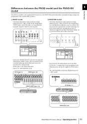
.../off ) for line level. • There is available as the standard PM5D model or as follows. ❏ PM5D model • Head amp adjustments (input sensitivity settings, phantom power (+48V) on/off . Phantom power can be saved in the analog domain. • ST IN jacks 1-4 are... only for the analog inputs (INPUT jacks 1-48, ST IN jacks 1-4) are controlled from within the screen via software. These models differ as the PM5D-RH model which allows internal head amp settings to be supplied...
.../off ) for line level. • There is available as the standard PM5D model or as follows. ❏ PM5D model • Head amp adjustments (input sensitivity settings, phantom power (+48V) on/off . Phantom power can be saved in the analog domain. • ST IN jacks 1-4 are... only for the analog inputs (INPUT jacks 1-48, ST IN jacks 1-4) are controlled from within the screen via software. These models differ as the PM5D-RH model which allows internal head amp settings to be supplied...
Owner's Manual
Page 17
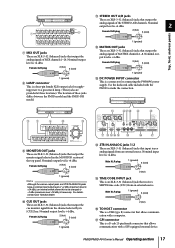
...XLR-3-32 (balanced) jacks that output the analog signals of the STEREO A/B channels. Nominal output level is +4 dBu. PM5D/PM5D-RH Owner's Manual Operating section 17 Nominal output level is an XLR-3-31 (balanced) jack that allows communication with a ...Yamaha dealer. Nominal output level is +4 dBu. Male XLR plug 1 (ground) 3 (cold) 2 (hot) P TO HOST connector This is a connector for supplying power to a gooseneck lamp. (These jacks are provided at three locations). Q GPI connector This is a four-pin female XLR output jack for connecting the PW800W power supply...
...XLR-3-32 (balanced) jacks that output the analog signals of the STEREO A/B channels. Nominal output level is +4 dBu. PM5D/PM5D-RH Owner's Manual Operating section 17 Nominal output level is an XLR-3-31 (balanced) jack that allows communication with a ...Yamaha dealer. Nominal output level is +4 dBu. Male XLR plug 1 (ground) 3 (cold) 2 (hot) P TO HOST connector This is a connector for supplying power to a gooseneck lamp. (These jacks are provided at three locations). Q GPI connector This is a four-pin female XLR output jack for connecting the PW800W power supply...

Owner's Manual
Page 28
... cue monitor signal of the channel that is currently selected by its [CUE] key. Main speakers 28 PM5D/PM5D-RH Owner's Manual Operating section 4 Connections and setup Analog output connections Monitor speakers Monitor speakers PW800W power supply MIX OUT MONITOR OUT CUE OUT C R L R L R L R L 8 7 6 5 4 3 2 1 DC POWER INPUT LA MATRIX OUT STEREO OUT Recorder, relay vehicle, etc.
... cue monitor signal of the channel that is currently selected by its [CUE] key. Main speakers 28 PM5D/PM5D-RH Owner's Manual Operating section 4 Connections and setup Analog output connections Monitor speakers Monitor speakers PW800W power supply MIX OUT MONITOR OUT CUE OUT C R L R L R L R L 8 7 6 5 4 3 2 1 DC POWER INPUT LA MATRIX OUT STEREO OUT Recorder, relay vehicle, etc.
Owner's Manual
Page 36
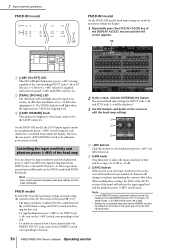
... edit the head amp settings. 1 2 3 A +48V button Click this button to switch phantom power (+48V) on /off setting for the signals being supplied to the corresponding INPUT jacks 1-48 or ST IN jacks 1-4. PM5D model For the PM5D model, head amp settings are made using the controls of the AD IN section of... jack. • To supply phantom power (+48V) to an INPUT jack 1-48, turn on the [+48V] switch corresponding to that jack. • To enable an external device that is inserted into the INSERT IN/OUT jacks, turn on the PM5D model and PM5DRH model. Note • On the PM5D-RH model, head amp...
... edit the head amp settings. 1 2 3 A +48V button Click this button to switch phantom power (+48V) on /off setting for the signals being supplied to the corresponding INPUT jacks 1-48 or ST IN jacks 1-4. PM5D model For the PM5D model, head amp settings are made using the controls of the AD IN section of... jack. • To supply phantom power (+48V) to an INPUT jack 1-48, turn on the [+48V] switch corresponding to that jack. • To enable an external device that is inserted into the INSERT IN/OUT jacks, turn on the PM5D model and PM5DRH model. Note • On the PM5D-RH model, head amp...

Owner's Manual
Page 97
... screen; About the TALKBACK/OSCILLATOR sections The TALKBACK and OSCILLATOR sections let you hold down the key. Signal flow in the display to supply +48V phantom power to the TALKBACK jack. C TALKBACK [ON] key This switches the talkback signal on . D OSCILLATOR [ON] key This is as... will turn it will remain on . 12 Talkback and Oscillator This chapter explains how to the desired output jacks. Talkback and Oscillator 12 PM5D/PM5D-RH Owner's Manual Operating section 97 B TALKBACK [LEVEL] knob This adjusts the input level of a test oscillator to use talkback and ...
... screen; About the TALKBACK/OSCILLATOR sections The TALKBACK and OSCILLATOR sections let you hold down the key. Signal flow in the display to supply +48V phantom power to the TALKBACK jack. C TALKBACK [ON] key This switches the talkback signal on . D OSCILLATOR [ON] key This is as... will turn it will remain on . 12 Talkback and Oscillator This chapter explains how to the desired output jacks. Talkback and Oscillator 12 PM5D/PM5D-RH Owner's Manual Operating section 97 B TALKBACK [LEVEL] knob This adjusts the input level of a test oscillator to use talkback and ...

Owner's Manual
Page 98
...the +48V button located in the TALKBACK OUT area to access the OUTPUT PATCH screen, and patch talkback to the jack you want phantom power (+48V) to be supplied to lower the monitor levels other than talkback (➥ p.216). • You can operate in either of the following buses. Hint ...TALKBACK ON/OFF button in the TALKBACK IN area indicates the input level of the mic connected to a user-defined key (➥ p.189). 98 PM5D/PM5D-RH Owner's Manual Operating section TALKBACK TALKBACK area BUS ASSIGN area INPUT TO TALKBACK area TALKBACK OUT area 2 Turn the TALKBACK [LEVEL] knob to...
...the +48V button located in the TALKBACK OUT area to access the OUTPUT PATCH screen, and patch talkback to the jack you want phantom power (+48V) to be supplied to lower the monitor levels other than talkback (➥ p.216). • You can operate in either of the following buses. Hint ...TALKBACK ON/OFF button in the TALKBACK IN area indicates the input level of the mic connected to a user-defined key (➥ p.189). 98 PM5D/PM5D-RH Owner's Manual Operating section TALKBACK TALKBACK area BUS ASSIGN area INPUT TO TALKBACK area TALKBACK OUT area 2 Turn the TALKBACK [LEVEL] knob to...
Owner's Manual
Page 126
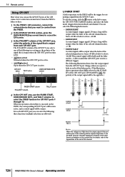
...GPI OUT area, select the polarity of this case there is a limitation on the PM5D, the corresponding GPI OUT port will become active, and a control signal will be the trigger for outputting a signal from the +5 power supply pin. The following fader modes. • FADER START A control signal (trigger signal)...select the following illustration shows how the output signal from the GPI OUT port changes when you operate a fader in this manual. 126 PM5D/PM5D-RH Owner's Manual Operating section To edit the setting, click the button at High level, the output signal of the port will be ...
...GPI OUT area, select the polarity of this case there is a limitation on the PM5D, the corresponding GPI OUT port will become active, and a control signal will be the trigger for outputting a signal from the +5 power supply pin. The following fader modes. • FADER START A control signal (trigger signal)...select the following illustration shows how the output signal from the GPI OUT port changes when you operate a fader in this manual. 126 PM5D/PM5D-RH Owner's Manual Operating section To edit the setting, click the button at High level, the output signal of the port will be ...
Owner's Manual
Page 128
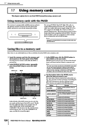
17 Using memory cards 17 Using memory cards This chapter explains how to save/load PM5D internal data using them with the PM5D. Using memory cards with a power supply voltage of the effect library 128 PM5D/PM5D-RH Owner's Manual Operating section If you do need to save modes provided are sold in... the right side of the PM5D. Note Operation is not guaranteed for saving. (You can ...
17 Using memory cards 17 Using memory cards This chapter explains how to save/load PM5D internal data using them with the PM5D. Using memory cards with a power supply voltage of the effect library 128 PM5D/PM5D-RH Owner's Manual Operating section If you do need to save modes provided are sold in... the right side of the PM5D. Note Operation is not guaranteed for saving. (You can ...
Owner's Manual
Page 147
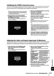
... use extreme caution when performing this operation. 1 While holding down the SCENE MEMORY [STORE] key of the panel, turn on the power of the PW800W power supply. CALIBRATE OUTPUT GAIN (make fine adjustments to the output ports) The OUTPUT TRIM window will appear, allowing you really want to...in the PM5D's internal memory, or if you are unable to return to normal operation because you to make fine adjustments to the gain of the specified analog input port. Adjusting the faders and input/output gain (Calibration) Depending on the power of the PW800W power supply. If...
... use extreme caution when performing this operation. 1 While holding down the SCENE MEMORY [STORE] key of the panel, turn on the power of the PW800W power supply. CALIBRATE OUTPUT GAIN (make fine adjustments to the output ports) The OUTPUT TRIM window will appear, allowing you really want to...in the PM5D's internal memory, or if you are unable to return to normal operation because you to make fine adjustments to the gain of the specified analog input port. Adjusting the faders and input/output gain (Calibration) Depending on the power of the PW800W power supply. If...

Owner's Manual
Page 195
...and the free area on the memory card. (The directory name is delineated by "\" characters.) B SCAN This scans the directory that is divided into the PM5D. In this button, the FILE DELETE window will appear, and the operation cannot be changed. Q MAKE DIR (Make directory) This button creates a new .../SIZE, and COMMENT. (To see the COMMENT field, use either PCMCIA Type II flash ATA cards or CompactFlash media inserted in a PC card adaptor (power supply voltage of 3.3V/5V in either change the filename or select a different directory in which to save the file. • When you to assign a...
...and the free area on the memory card. (The directory name is delineated by "\" characters.) B SCAN This scans the directory that is divided into the PM5D. In this button, the FILE DELETE window will appear, and the operation cannot be changed. Q MAKE DIR (Make directory) This button creates a new .../SIZE, and COMMENT. (To see the COMMENT field, use either PCMCIA Type II flash ATA cards or CompactFlash media inserted in a PC card adaptor (power supply voltage of 3.3V/5V in either change the filename or select a different directory in which to save the file. • When you to assign a...

Owner's Manual
Page 199
...operate. In order to protect your speaker system, be sure to turn down the power amp output before changing the word clock setting. • If you attempt to select a channel whose SRC is on which the PM5D is occurring normally between that the sampling rate converter will operate. Information shown in ... sampling frequency at the output jacks when the word clock setting is shown by the color of each clock is changed. nected PM5D 2TR IN D1 The clock data of the digital audio signal supplied from 2TR IN DIGITAL connector 1 2TR IN D2 The clock data of the digital audio signal...
...operate. In order to protect your speaker system, be sure to turn down the power amp output before changing the word clock setting. • If you attempt to select a channel whose SRC is on which the PM5D is occurring normally between that the sampling rate converter will operate. Information shown in ... sampling frequency at the output jacks when the word clock setting is shown by the color of each clock is changed. nected PM5D 2TR IN D1 The clock data of the digital audio signal supplied from 2TR IN DIGITAL connector 1 2TR IN D2 The clock data of the digital audio signal...

Owner's Manual
Page 344
... contact your Yamaha dealer. File Already Exist! Saving Aborted. Additional Cascade Unit Detected. Couldn't Store Scene on Slave Console! Processing Aborted. Meaning Parameter Lock has been enabled. The memory card already contain a file/directory with the PW800W power supply connected to... Messages Message Parameter Locked. Parameter Unlocked. Cannot Paste to control is no data in the slots exceed the rated power capacity. 344 PM5D/PM5D-RH Owner's Manual Reference section No Controllable Gain. Tap Operation Ignored. Cascade Unit Disconnected. No Response from an ...
... contact your Yamaha dealer. File Already Exist! Saving Aborted. Additional Cascade Unit Detected. Couldn't Store Scene on Slave Console! Processing Aborted. Meaning Parameter Lock has been enabled. The memory card already contain a file/directory with the PW800W power supply connected to... Messages Message Parameter Locked. Parameter Unlocked. Cannot Paste to control is no data in the slots exceed the rated power capacity. 344 PM5D/PM5D-RH Owner's Manual Reference section No Controllable Gain. Tap Operation Ignored. Cascade Unit Disconnected. No Response from an ...
Owner's Manual
Page 346
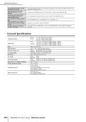
... the paired input channels to +60 °C Owner's Manual Gooseneck Lamps x 3 Power Supply PW800W Connection Cable Studio Manager CD-ROM Studio Manager Installation Guide mini YGDAI cards Power Supply PW800W Power Supply Link Cable PSL120 346 PM5D/PM5D-RH Owner's Manual Reference section General Specifications You paired input channels, but it takes ... External: 44.1 kHz, 48 kHz, 88.2 kHz, 96 kHz 44.1 kHz (-10%) to 48 kHz (+6%) 88.2 kHz (-10%) to 96 kHz (+6%) PM5D: PM5D-RH: Less than 2.3 ms INPUT to STEREO A,B (@Fs = 48 kHz) Less than 1.15 ms INPUT to STEREO A,B (@Fs = 96 kHz) Less than...
... the paired input channels to +60 °C Owner's Manual Gooseneck Lamps x 3 Power Supply PW800W Connection Cable Studio Manager CD-ROM Studio Manager Installation Guide mini YGDAI cards Power Supply PW800W Power Supply Link Cable PSL120 346 PM5D/PM5D-RH Owner's Manual Reference section General Specifications You paired input channels, but it takes ... External: 44.1 kHz, 48 kHz, 88.2 kHz, 96 kHz 44.1 kHz (-10%) to 48 kHz (+6%) 88.2 kHz (-10%) to 96 kHz (+6%) PM5D: PM5D-RH: Less than 2.3 ms INPUT to STEREO A,B (@Fs = 48 kHz) Less than 1.15 ms INPUT to STEREO A,B (@Fs = 96 kHz) Less than...

Owner's Manual
Page 351
..., Maximum Rating: 5V) Output Pin: Open Collector (Vmax=12V, Imax/pin=75 mA, GPO1-8: Total Imax=300 mA, GPO9-12: Total Imax=300 mA) Power Pin: Power Supply (Vp=5V, Imax/2 pin=500 mA) ❏ SLOT 1-4 Characteristics Card Name MY8-AT MY8-TD MY8-AE MY4-AD MY8-AD MY4-DA MY8-AD24... 8 IN - 8 IN - 8 IN 16 IN 16 IN Output 8 OUT - 4 OUT - 8 OUT The Number Of Usable Cards 4 16 OUT 16 OUT Output functions Input functions Appendices PM5D/PM5D-RH Owner's Manual Reference section 351
..., Maximum Rating: 5V) Output Pin: Open Collector (Vmax=12V, Imax/pin=75 mA, GPO1-8: Total Imax=300 mA, GPO9-12: Total Imax=300 mA) Power Pin: Power Supply (Vp=5V, Imax/2 pin=500 mA) ❏ SLOT 1-4 Characteristics Card Name MY8-AT MY8-TD MY8-AE MY4-AD MY8-AD MY4-DA MY8-AD24... 8 IN - 8 IN - 8 IN 16 IN 16 IN Output 8 OUT - 4 OUT - 8 OUT The Number Of Usable Cards 4 16 OUT 16 OUT Output functions Input functions Appendices PM5D/PM5D-RH Owner's Manual Reference section 351

V1.05 Supplementary Manual
Page 1
... Supplementary Manual PM5D system software V1.05 includes the following changes and additions relative to the RECALL SAFE screen and SELECTIVE RECALL screen. Switch parameter value indication on ... been added to the corresponding channel. If this option is on /off operations A new SAFE KEY MODE SELECT section has been added to turn phantom power supply (+48V) on , Recall Safe and Selective Recall will turn on . In V1.04 and earlier, operating the fader or encoder (pan setting) of each encoder...
... Supplementary Manual PM5D system software V1.05 includes the following changes and additions relative to the RECALL SAFE screen and SELECTIVE RECALL screen. Switch parameter value indication on ... been added to the corresponding channel. If this option is on /off operations A new SAFE KEY MODE SELECT section has been added to turn phantom power supply (+48V) on , Recall Safe and Selective Recall will turn on . In V1.04 and earlier, operating the fader or encoder (pan setting) of each encoder...

V1.10 Supplementary Manual
Page 1
...been added to the PREFERENCE 2 screen. In V1.04 and earlier, operating the fader or encoder (pan setting) of each encoder to turn phantom power supply (+48V) on one source from appearing when you to select a single monitor source more rapidly. Support for the Y96K card (from the Waves Corporation..../off operations A new SAFE KEY MODE SELECT section has been added to the RECALL SAFE screen. These additions are also included). PM5D V1.10 Supplementary Manual PM5D system software V1.10 includes the following changes and additions relative to V1.04 (changes in V1.05 are in order to support...
...been added to the PREFERENCE 2 screen. In V1.04 and earlier, operating the fader or encoder (pan setting) of each encoder to turn phantom power supply (+48V) on one source from appearing when you to select a single monitor source more rapidly. Support for the Y96K card (from the Waves Corporation..../off operations A new SAFE KEY MODE SELECT section has been added to the RECALL SAFE screen. These additions are also included). PM5D V1.10 Supplementary Manual PM5D system software V1.10 includes the following changes and additions relative to V1.04 (changes in V1.05 are in order to support...

V1.12 Supplementary Manual
Page 1
...exclude just the DCA group name from DCA group Recall Safe and Selective Recall. PM5D V1.12 Supplementary Manual PM5D system software V1.12 includes the following changes and additions relative to V1.04 .../off operations (from [2TR A1]-[2TR D3] or [DEFINE] and one key will now also turn phantom power supply (+48V) on , and HA (head amp input sensitivity) is selected as the encoder mode, you want...VIEW screen (INPUT VIEW function) to the corresponding channel. If the CH button is off will turn phantom power (+48V) on . In V1.05 and later, turning on /off in V1.04 or earlier, you...
...exclude just the DCA group name from DCA group Recall Safe and Selective Recall. PM5D V1.12 Supplementary Manual PM5D system software V1.12 includes the following changes and additions relative to V1.04 .../off operations (from [2TR A1]-[2TR D3] or [DEFINE] and one key will now also turn phantom power supply (+48V) on , and HA (head amp input sensitivity) is selected as the encoder mode, you want...VIEW screen (INPUT VIEW function) to the corresponding channel. If the CH button is off will turn phantom power (+48V) on . In V1.05 and later, turning on /off in V1.04 or earlier, you...

V1.20 Supplementary Manual
Page 1
In V1.04 and earlier, operating the fader or encoder (pan setting) of each encoder to turn phantom power supply (+48V) on/off. In V1.05 and later, turning the "ENCODER VALUE" and "FADER VALUE" options off will prevent the respective parameter value from appearing ... to turn on the HA+CH button, using the [RECALL SAFE] key of DCA groups for the HA patched to the corresponding channel. PM5D V1.20 Supplementary Manual PM5D system software V1.20 includes the following changes and additions relative to V1.04 (changes up to V1.12 are on. EN If...
In V1.04 and earlier, operating the fader or encoder (pan setting) of each encoder to turn phantom power supply (+48V) on/off. In V1.05 and later, turning the "ENCODER VALUE" and "FADER VALUE" options off will prevent the respective parameter value from appearing ... to turn on the HA+CH button, using the [RECALL SAFE] key of DCA groups for the HA patched to the corresponding channel. PM5D V1.20 Supplementary Manual PM5D system software V1.20 includes the following changes and additions relative to V1.04 (changes up to V1.12 are on. EN If...


