
Owner's Manual
Page 6
... Moving the cursor 23 Scrolling the screen 24 Operating the buttons 25 Adjusting the setting of a knob or fader 25 Assigning a name 26 4 Connections and setup 27 Audio connections 27 Analog audio connections 27 Analog output connections 28 Digital input/output connections 29 Installing an option card 30 Word clock connections and settings 31 About word clock 31 Selecting the word clock master 31 Restoring the current scene to the default state .......... 32 5 Input channel operations 33 About the input channels 33 AD IN section 35...
... Moving the cursor 23 Scrolling the screen 24 Operating the buttons 25 Adjusting the setting of a knob or fader 25 Assigning a name 26 4 Connections and setup 27 Audio connections 27 Analog audio connections 27 Analog output connections 28 Digital input/output connections 29 Installing an option card 30 Word clock connections and settings 31 About word clock 31 Selecting the word clock master 31 Restoring the current scene to the default state .......... 32 5 Input channel operations 33 About the input channels 33 AD IN section 35...
Owner's Manual
Page 7
... metering point for output channels.......... 101 Viewing the gain reduction of the internal gates and compressors 102 Viewing the gain reduction for input channels 102 Viewing the gain reduction for output channels 102 14 Effects 103 About the internal effects 103 Using an internal effect via a MIX bus 104 Inserting an internal effect into a channel 105 Basic operations in the effect screen 106 Recalling settings from the effect library 106 Editing the effect parameters 106 Storing settings in the effect library 107 Using the Tap Tempo function...
... metering point for output channels.......... 101 Viewing the gain reduction of the internal gates and compressors 102 Viewing the gain reduction for input channels 102 Viewing the gain reduction for output channels 102 14 Effects 103 About the internal effects 103 Using an internal effect via a MIX bus 104 Inserting an internal effect into a channel 105 Basic operations in the effect screen 106 Recalling settings from the effect library 106 Editing the effect parameters 106 Storing settings in the effect library 107 Using the Tap Tempo function...
Owner's Manual
Page 10
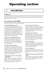
... can also be inserted into any channel or any output. ❏ Scene memories and libraries Mix parameters and internal effect settings can be installed in a safe place. In order to control the send level and master level. AD cards, DA cards, or digital I /O card expansion The rear panel provides four slots in a wide range of trouble-free use them as group faders. ❏ PM5D model and PM5D-RH model In addition to 110 dB of cutting-edge digital audio processing technology. 24...
... can also be inserted into any channel or any output. ❏ Scene memories and libraries Mix parameters and internal effect settings can be installed in a safe place. In order to control the send level and master level. AD cards, DA cards, or digital I /O card expansion The rear panel provides four slots in a wide range of trouble-free use them as group faders. ❏ PM5D model and PM5D-RH model In addition to 110 dB of cutting-edge digital audio processing technology. 24...
Owner's Manual
Page 32
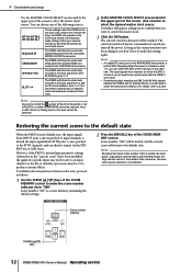
... current scene will operate as the word clock master. You can choose one of two channels. The PM5D will also return to produce extreme effects. 4 Connections and setup Use the MASTER CLOCK SELECT area located in the upper part of the screen to the ST IN channels, and can then be output via the STEREO bus or MIX buses. The input signals from a digital I /O card (such as follows. 1 Use the SCENE [π]/[†] keys of the SCENE MEMORY section...
... current scene will operate as the word clock master. You can choose one of two channels. The PM5D will also return to produce extreme effects. 4 Connections and setup Use the MASTER CLOCK SELECT area located in the upper part of the screen to the ST IN channels, and can then be output via the STEREO bus or MIX buses. The input signals from a digital I /O card (such as follows. 1 Use the SCENE [π]/[†] keys of the SCENE MEMORY section...
Owner's Manual
Page 34
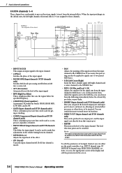
...; LEVEL/DCA 1-8 Adjusts the input level of an input channel, you can be used mainly to make fine adjustments in the screen. 34 PM5D/PM5D-RH Owner's Manual Operating section It can choose from the input channel to MIX buses 1-24. To edit the parameters of the effect. • ON (On/off) Turns the input channel on /off , that channel is muted. • PAN Adjusts the panning of the input signal. • HPF (High Pass Filter) This is connected...
...; LEVEL/DCA 1-8 Adjusts the input level of an input channel, you can be used mainly to make fine adjustments in the screen. 34 PM5D/PM5D-RH Owner's Manual Operating section It can choose from the input channel to MIX buses 1-24. To edit the parameters of the effect. • ON (On/off) Turns the input channel on /off , that channel is muted. • PAN Adjusts the panning of the input signal. • HPF (High Pass Filter) This is connected...
Owner's Manual
Page 66
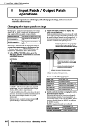
... IN jacks 1-4 (L/R) Output signals of input ports assigned to access the INPUT PATCH screen. The following input ports. To view input ports that are not currently visible, use the vertical scroll bar. The INPUT PATCH screen is where you assign input ports to input channels. To see channels that are assigned to display a " " symbol. Changing the input patch settings The input patch section lets you can patch (assign) input ports (rear panel input jacks or input channels of internal effects 1-8 2TR IN DIGITAL jacks 1-3 (L/R) 2TR...
... IN jacks 1-4 (L/R) Output signals of input ports assigned to access the INPUT PATCH screen. The following input ports. To view input ports that are not currently visible, use the vertical scroll bar. The INPUT PATCH screen is where you assign input ports to input channels. To see channels that are assigned to display a " " symbol. Changing the input patch settings The input patch section lets you can patch (assign) input ports (rear panel input jacks or input channels of internal effects 1-8 2TR IN DIGITAL jacks 1-3 (L/R) 2TR...
Owner's Manual
Page 74
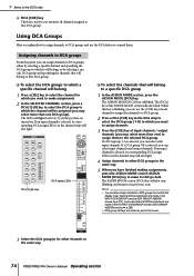
... as part of the scene. 3 Select the DCA group(s) for which you want to assign channels. 3 Press the [CUE] key of the FADER MODE section will also blink. If an input channel is selected, its corresponding DCA assign LED(s) in the channel strip will also light. 4 Assign channels to other channels in the same way. 74 PM5D/PM5D-RH Owner's Manual Operating section Assigning channels to DCA groups From the panel, you can also assign channels to control them...
... as part of the scene. 3 Select the DCA group(s) for which you want to assign channels. 3 Press the [CUE] key of the FADER MODE section will also blink. If an input channel is selected, its corresponding DCA assign LED(s) in the channel strip will also light. 4 Assign channels to other channels in the same way. 74 PM5D/PM5D-RH Owner's Manual Operating section Assigning channels to DCA groups From the panel, you can also assign channels to control them...
Owner's Manual
Page 78
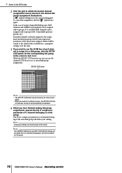
... groups A-F, and MATRIX channels can use the [CUE] key of channels belonging to the same compressor link group. 78 PM5D/PM5D-RH Owner's Manual Operating section A " " symbol will automatically be turned on for channels belonging to the same link group will follow your editing. SET BY CUE button Note • The SET BY CUE button can be defeated. 4 When you have finished making link group assignments, operate the EQ or compressor parameters of the scene. Note The STEREO LINK button and KEY IN SOURCE settings...
... groups A-F, and MATRIX channels can use the [CUE] key of channels belonging to the same compressor link group. 78 PM5D/PM5D-RH Owner's Manual Operating section A " " symbol will automatically be turned on for channels belonging to the same link group will follow your editing. SET BY CUE button Note • The SET BY CUE button can be defeated. 4 When you have finished making link group assignments, operate the EQ or compressor parameters of the scene. Note The STEREO LINK button and KEY IN SOURCE settings...

Owner's Manual
Page 104
... assigned, a window will appear when you press the [ENTER] key, asking you want to use an internal effect via a MIX bus. Don't raise the encoder of MIX channel 1 to confirm the assignment. This box selects the operation of the L CH box to confirm the assignment. EFFECT PARAM The effect module you can turn on the [MIX SEND] key of the MIX section, then use the input channel encoders to adjust the send level from each channel to MIX bus 1. 9 Turn...
... assigned, a window will appear when you press the [ENTER] key, asking you want to use an internal effect via a MIX bus. Don't raise the encoder of MIX channel 1 to confirm the assignment. This box selects the operation of the L CH box to confirm the assignment. EFFECT PARAM The effect module you can turn on the [MIX SEND] key of the MIX section, then use the input channel encoders to adjust the send level from each channel to MIX bus 1. 9 Turn...
Owner's Manual
Page 114
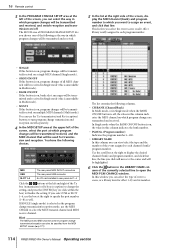
... in which program changes will be specified from the MIDI SETUP screen (➥ p.171). If SINGLE (single mode) is on, program changes will be transmitted/received, and the MIDI channel that line; 16 Remote control 3 In the PROGRAM CHANGE SETUP area at the left of the screen, you can select the type of event (a scene, or a library item for effect 1-8) and its number. 114 PM5D/PM5D-RH Owner's Manual Operating section The list contains the...
... in which program changes will be specified from the MIDI SETUP screen (➥ p.171). If SINGLE (single mode) is on, program changes will be transmitted/received, and the MIDI channel that line; 16 Remote control 3 In the PROGRAM CHANGE SETUP area at the left of the screen, you can select the type of event (a scene, or a library item for effect 1-8) and its number. 114 PM5D/PM5D-RH Owner's Manual Operating section The list contains the...
Owner's Manual
Page 147
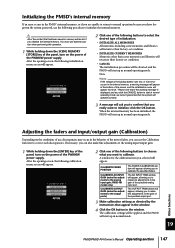
... analog input/output gain. 1 While holding down the [ENTER] key of the panel, turn on the power of the screen, and the initialization menu will appear at the bottom of the PW800W power supply. The calibration settings will be applied, and the PM5D will start up in the internal memory, a warning message will appear "by the instructions that appear in the window. 4 Click the OK button in normal operating mode...
... analog input/output gain. 1 While holding down the [ENTER] key of the panel, turn on the power of the screen, and the initialization menu will appear at the bottom of the PW800W power supply. The calibration settings will be applied, and the PM5D will start up in the internal memory, a warning message will appear "by the instructions that appear in the window. 4 Click the OK button in normal operating mode...
Owner's Manual
Page 150
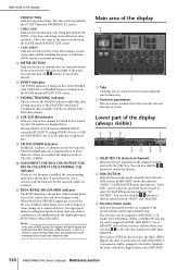
... LEVEL, MIX SEND 1-24, or REMOTE. J SOLO/INPUT CUE/DCA CUE/OUTPUT CUE/ KEY IN CUE/EFFECT CUE/EXTERNAL CUE indicator If Solo or Cue Monitor is enabled, the corresponding indicator is displayed here. If more than REMOTE. However, active sensing, MIDI clock, and quarter time code messages will appear briefly. In MIX SEND mode this indicates "SEND," in the SYS/W.CLOCK function MIXER SETUP screen the BUS SETUP setting STEREO B is shown. Similarly, the faders will be flipped if you can be assigned to directly select...
... LEVEL, MIX SEND 1-24, or REMOTE. J SOLO/INPUT CUE/DCA CUE/OUTPUT CUE/ KEY IN CUE/EFFECT CUE/EXTERNAL CUE indicator If Solo or Cue Monitor is enabled, the corresponding indicator is displayed here. If more than REMOTE. However, active sensing, MIDI clock, and quarter time code messages will appear briefly. In MIX SEND mode this indicates "SEND," in the SYS/W.CLOCK function MIXER SETUP screen the BUS SETUP setting STEREO B is shown. Similarly, the faders will be flipped if you can be assigned to directly select...
Owner's Manual
Page 178
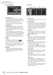
... fader mode and channel. While this button is on , the range of voltage variation will be performed. the range will be appropriate for the voltages being input from the GPI PORT. (For details on using a two-dimensional controller such as a joystick, specify a port for the corresponding port. J REVERSE This button inverts the low/high level of the input, changing the displayed direction of the output signal...
... fader mode and channel. While this button is on , the range of voltage variation will be performed. the range will be appropriate for the voltages being input from the GPI PORT. (For details on using a two-dimensional controller such as a joystick, specify a port for the corresponding port. J REVERSE This button inverts the low/high level of the input, changing the displayed direction of the output signal...

Owner's Manual
Page 188
... one of the following as the time code shown in the SCENE function EVENT LIST screen. • CASCADE/Fs Indicates the master/slave status when using a cascade connection, and the sampling frequency at which scene memories and library items will appear in a dark environment. J SCREEN TIPS • SHOW SCREEN TIPS If this button is on , LEDs corresponding to a specific reference value (e.g., 0 dB or CENTER) will...
... one of the following as the time code shown in the SCENE function EVENT LIST screen. • CASCADE/Fs Indicates the master/slave status when using a cascade connection, and the sampling frequency at which scene memories and library items will appear in a dark environment. J SCREEN TIPS • SHOW SCREEN TIPS If this button is on , LEDs corresponding to a specific reference value (e.g., 0 dB or CENTER) will...

Owner's Manual
Page 190
.../DISABLE button in the TRACKING RECALL screen The same function as the OFFSET LOCK button in the TRACKING RECALL screen Switch the Tracking Recall function on/off for the currently selected channel When an output channel is selected, turn talkback transmission on/off for that channel Send the talkback signal to the specified output channel Monitor the desired MIX/MATRIX channel *1 Switch on the monitor dimmer function Control the Tap Tempo function in the displayed screen Control the Tap Tempo function of the specified effect Use a joystick assigned...
.../DISABLE button in the TRACKING RECALL screen The same function as the OFFSET LOCK button in the TRACKING RECALL screen Switch the Tracking Recall function on/off for the currently selected channel When an output channel is selected, turn talkback transmission on/off for that channel Send the talkback signal to the specified output channel Monitor the desired MIX/MATRIX channel *1 Switch on the monitor dimmer function Control the Tap Tempo function in the displayed screen Control the Tap Tempo function of the specified effect Use a joystick assigned...

Owner's Manual
Page 345
..., panel LEDs and the LCD display do not light ❍ Are the PM5D and PW800W correctly connected by the special power cable? ❍ Is the PW800W's POWER switch turned on ? Only the sound of the METER function to check the levels. (➥ p.209, 210) ❍ Is the DCA fader assigned to an appropriate volume? Turning a MIX encoder does not ❍ Is the MIX [ON] key turned on ? PHONES jack Noise occurs from headphones or the MONITOR...
..., panel LEDs and the LCD display do not light ❍ Are the PM5D and PW800W correctly connected by the special power cable? ❍ Is the PW800W's POWER switch turned on ? Only the sound of the METER function to check the levels. (➥ p.209, 210) ❍ Is the DCA fader assigned to an appropriate volume? Turning a MIX encoder does not ❍ Is the MIX [ON] key turned on ? PHONES jack Noise occurs from headphones or the MONITOR...

Owner's Manual
Page 361
... MIX SEND VIEW 280 SURR PARAM 283 SURR VIEW 285 Panels 14 Parameter Lock 142 Parameters that can be assigned to control changes......... 312 PASTE MODE 89 Patch 66 Patching Insert-out and insert-in 70 Pattern 136 Phantom power 36 Phase 59 Pin Assignment 355 PM5D, PM5D-RH model 11 Pointer 19 PREFERENCE 1/2 186 PRESENT TIME 149 PREVIEW indicator 82 PREVIEW mode 82 Program changes 113 R Rear panel 16 RECALL SAFE 86, 166 Recall...
... MIX SEND VIEW 280 SURR PARAM 283 SURR VIEW 285 Panels 14 Parameter Lock 142 Parameters that can be assigned to control changes......... 312 PASTE MODE 89 Patch 66 Patching Insert-out and insert-in 70 Pattern 136 Phantom power 36 Phase 59 Pin Assignment 355 PM5D, PM5D-RH model 11 Pointer 19 PREFERENCE 1/2 186 PRESENT TIME 149 PREVIEW indicator 82 PREVIEW mode 82 Program changes 113 R Rear panel 16 RECALL SAFE 86, 166 Recall...
Studio Manager Installation Guide
Page 6
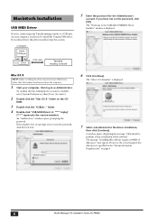
.... Computer Studio Manager Driver USB cable Yamaha mixing console 5 Enter the password for PM5D) To confirm that the Administrator account is specified in as Administrator. However, the actual required free disk space is available, select [System Preferences], then [Users (Account)]. 2 Double-click the "Mac OS X" folder on page 6. 6 Studio Manager V2 Installation Guide (for the Administrator's account. Macintosh Installation USB MIDI Driver If you're connecting your Yamaha mixing console to a USB port on...
.... Computer Studio Manager Driver USB cable Yamaha mixing console 5 Enter the password for PM5D) To confirm that the Administrator account is specified in as Administrator. However, the actual required free disk space is available, select [System Preferences], then [Users (Account)]. 2 Double-click the "Mac OS X" folder on page 6. 6 Studio Manager V2 Installation Guide (for the Administrator's account. Macintosh Installation USB MIDI Driver If you're connecting your Yamaha mixing console to a USB port on...
Studio Manager Installation Guide
Page 7
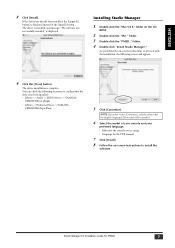
... English-language PDF manual will appear. 9 Click the [Close] button. Installing Studio Manager 1 Double-click the "Mac OS X" folder on -screen instructions to confirm that the driver has been installed: • Library -> Audio -> MIDI Drivers -> YAMAHA- The driver installation is displayed instead of your console and your preferred language. • Editor for PM5D) 7 If the driver has already been installed, the [Upgrade] button is complete. The driver is installed, and message "The software was successfully installed" is displayed. ENGLISH 8 Click [Install...
... English-language PDF manual will appear. 9 Click the [Close] button. Installing Studio Manager 1 Double-click the "Mac OS X" folder on -screen instructions to confirm that the driver has been installed: • Library -> Audio -> MIDI Drivers -> YAMAHA- The driver installation is displayed instead of your console and your preferred language. • Editor for PM5D) 7 If the driver has already been installed, the [Upgrade] button is complete. The driver is installed, and message "The software was successfully installed" is displayed. ENGLISH 8 Click [Install...

V1.20 Supplementary Manual
Page 4
... for Recall Safe operation. ■ Input channels Parameter Recall Safe HA NAME PHASE MS DECODE LCR Fade Time Insert Direct Out On Fader PAN Att Gate Comp HPF EQ Delay On Delay TIME Surround LFE Surround Div Surround Div Rear Surround Div Link Mute Assign DCA Assign To Stereo On To Mix Follow Pan To Mix ON To Mix LEVEL To Mix PAN To Mix PRE/POST PAIR Global Paste Solo Safe Cue Key In Cue Mute Safe Selective Recall Tracking Recall Pair...
... for Recall Safe operation. ■ Input channels Parameter Recall Safe HA NAME PHASE MS DECODE LCR Fade Time Insert Direct Out On Fader PAN Att Gate Comp HPF EQ Delay On Delay TIME Surround LFE Surround Div Surround Div Rear Surround Div Link Mute Assign DCA Assign To Stereo On To Mix Follow Pan To Mix ON To Mix LEVEL To Mix PAN To Mix PRE/POST PAIR Global Paste Solo Safe Cue Key In Cue Mute Safe Selective Recall Tracking Recall Pair...


