
Owner's Manual
Page 1
DIGITAL MIXING CONSOLE PM5D / PM5D-RH Owner's Manual
DIGITAL MIXING CONSOLE PM5D / PM5D-RH Owner's Manual

Owner's Manual
Page 2
...all installations. A grounding type plug has two blades and a third grounding prong. FCC INFORMATION (U.S.A.) 1. Modifications not expressly approved by Yamaha may void your authority, granted by using one wider than the other electronic devices. If these requirements provides a reasonable level of other . ...Install in the users manual, may be determined by turning the unit "OFF" and "ON", please try to eliminate the problem by the FCC, to...
...all installations. A grounding type plug has two blades and a third grounding prong. FCC INFORMATION (U.S.A.) 1. Modifications not expressly approved by Yamaha may void your authority, granted by using one wider than the other electronic devices. If these requirements provides a reasonable level of other . ...Install in the users manual, may be determined by turning the unit "OFF" and "ON", please try to eliminate the problem by the FCC, to...
Owner's Manual
Page 4
...or during electrical storms. • When removing the electric plug from electrical shock, short-circuiting, damages, fire or other hazards. Pulling by Yamaha). • Only use the voltage specified as a bookcase or closet. • Do not use four or more people. • ...Do not expose the device to prevent the internal temperature from the outlet, and have the device inspected by qualified Yamaha service personnel. • If this manual in the vicinity of a TV, radio, stereo equipment, mobile phone, or other electric devices. This device has ventilation holes ...
...or during electrical storms. • When removing the electric plug from electrical shock, short-circuiting, damages, fire or other hazards. Pulling by Yamaha). • Only use the voltage specified as a bookcase or closet. • Do not use four or more people. • ...Do not expose the device to prevent the internal temperature from the outlet, and have the device inspected by qualified Yamaha service personnel. • If this manual in the vicinity of a TV, radio, stereo equipment, mobile phone, or other electric devices. This device has ventilation holes ...
Owner's Manual
Page 6
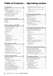
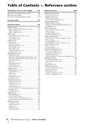
...1 Introduction 10 Thank you 10 An overview of the PM5D 10 Differences between the PM5D model and the PM5D-RH model 11 About the channel structure of the PM5D 12 Regarding word clock synchronization 12 How this manual is organized 13 Conventions in this manual 13 2 Top, front, and rear panels 14 Top ...panel 14 Rear panel 16 Front panel 18 3 Basic operation on the PM5D 19 About the various types of ...
...1 Introduction 10 Thank you 10 An overview of the PM5D 10 Differences between the PM5D model and the PM5D-RH model 11 About the channel structure of the PM5D 12 Regarding word clock synchronization 12 How this manual is organized 13 Conventions in this manual 13 2 Top, front, and rear panels 14 Top ...panel 14 Rear panel 16 Front panel 18 3 Basic operation on the PM5D 19 About the various types of ...
Owner's Manual
Page 7
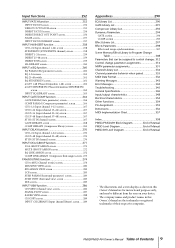
...in the FADER MODE section 139 Assigning channels to DCA faders 139 Controlling the channels assigned to DCA faders 140 Locking the PM5D (Security functions 141 Setting the System Password or Console Password.......... 141 Using Parameter Lock or Console Lock 142 Using cascade ... using the USB TO HOST connector ........ 146 Initializing the PM5D's internal memory 147 Adjusting the faders and input/output gain (Calibration 147 Calibrating the faders 148 Adjusting the analog input gain (PM5D-RH model only 148 Adjusting the output gain 148 PM5D/PM5D-RH Owner's Manual Table of Contents 7
...in the FADER MODE section 139 Assigning channels to DCA faders 139 Controlling the channels assigned to DCA faders 140 Locking the PM5D (Security functions 141 Setting the System Password or Console Password.......... 141 Using Parameter Lock or Console Lock 142 Using cascade ... using the USB TO HOST connector ........ 146 Initializing the PM5D's internal memory 147 Adjusting the faders and input/output gain (Calibration 147 Calibrating the faders 148 Adjusting the analog input gain (PM5D-RH model only 148 Adjusting the output gain 148 PM5D/PM5D-RH Owner's Manual Table of Contents 7
Owner's Manual
Page 8
... CH VIEW (Channel view) screen 245 SIGNAL FLOW screen 247 FADER VIEW screen 249 CH COPY (Channel copy) screen 249 OUTPUT CH LIBRARY screen 251 8 PM5D/PM5D-RH Owner's Manual Table of Contents -
... CH VIEW (Channel view) screen 245 SIGNAL FLOW screen 247 FADER VIEW screen 249 CH COPY (Channel copy) screen 249 OUTPUT CH LIBRARY screen 251 8 PM5D/PM5D-RH Owner's Manual Table of Contents -
Owner's Manual
Page 9
... Functions 354 Pin Assignment 355 Dimensions 356 MIDI Implementation Chart 357 Index 358 PM5D/PM5D-RH Block Diagram End of Manual PM5D Level Diagram End of Manual PM5D-RH Level Diagram End of Manual • The illustrations and screen displays as shown in this Owner's Manual are for instructional purposes only, and may be different from the ones...
... Functions 354 Pin Assignment 355 Dimensions 356 MIDI Implementation Chart 357 Index 358 PM5D/PM5D-RH Block Diagram End of Manual PM5D Level Diagram End of Manual PM5D-RH Level Diagram End of Manual • The illustrations and screen displays as shown in this Owner's Manual are for instructional purposes only, and may be different from the ones...
Owner's Manual
Page 10
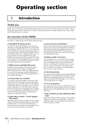
...-free use, please read the manual, keep it in the digital domain. In order to take full advantage of the PM5D's superior functionality and enjoy years of scenes. ❏ Digital cascade connection Up to four PM5D units, or one PM5D and one Yamaha DM2000/02R96 unit, can be ... dedicated channel strips are available. ❏ I /O cards can be used as inserts or as an Add-On Effect for purchasing the Yamaha PM5D digital mixing console. After you for the DM2000 or 02R96 is also available, providing programmable control of applications. Compatible external devices can also ...
...-free use, please read the manual, keep it in the digital domain. In order to take full advantage of the PM5D's superior functionality and enjoy years of scenes. ❏ Digital cascade connection Up to four PM5D units, or one PM5D and one Yamaha DM2000/02R96 unit, can be ... dedicated channel strips are available. ❏ I /O cards can be used as inserts or as an Add-On Effect for purchasing the Yamaha PM5D digital mixing console. After you for the DM2000 or 02R96 is also available, providing programmable control of applications. Compatible external devices can also ...
Owner's Manual
Page 11
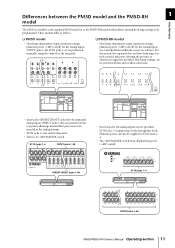
... MASTER switch. These models differ as the PM5D-RH model which allows internal head amp settings to ST IN jacks 1- 4. • The +48V MASTER switch turns all phantom power (+48V) on/off ) for the analog inputs (INPUT jacks 1-48, ST IN jacks 1-4) are performed manually, using the controls of a signal are not... time. • Insert jacks (INSERT IN/OUT jacks) for the analog inputs are provided. INSERT IN/OUT jacks 1-48 ST IN jacks 1-4 INPUT jacks 1-48 PM5D/PM5D-RH Owner's Manual Operating section 11
... MASTER switch. These models differ as the PM5D-RH model which allows internal head amp settings to ST IN jacks 1- 4. • The +48V MASTER switch turns all phantom power (+48V) on/off ) for the analog inputs (INPUT jacks 1-48, ST IN jacks 1-4) are performed manually, using the controls of a signal are not... time. • Insert jacks (INSERT IN/OUT jacks) for the analog inputs are provided. INSERT IN/OUT jacks 1-48 ST IN jacks 1-4 INPUT jacks 1-48 PM5D/PM5D-RH Owner's Manual Operating section 11
Owner's Manual
Page 12
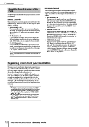
... to these channels. Be aware that contains a sampling rate converter, or via the 2TR IN/OUT DIGITAL jacks. 12 PM5D/PM5D-RH Owner's Manual Operating section These channels are used to synchronize digital audio signal processing is not synchronized, the signals will not be synchronized between...from input channels to MIX buses, and output them from the internal effects. 2 Introduction About the channel structure of the PM5D The PM5D provides the following input channels and output channels. ❏ Input channels This section processes input signals and sends them to STEREO ...
... to these channels. Be aware that contains a sampling rate converter, or via the 2TR IN/OUT DIGITAL jacks. 12 PM5D/PM5D-RH Owner's Manual Operating section These channels are used to synchronize digital audio signal processing is not synchronized, the signals will not be synchronized between...from input channels to MIX buses, and output them from the internal effects. 2 Introduction About the channel structure of the PM5D The PM5D provides the following input channels and output channels. ❏ Input channels This section processes input signals and sends them to STEREO ...
Owner's Manual
Page 13
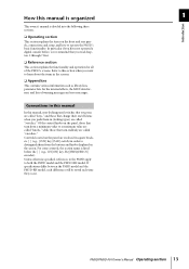
...; Appendices This contains various information such as library lists, parameter lists for all of warning messages and error messages. PM5D/PM5D-RH Owner's Manual Operating section 13 Controls located on /off status when you press are called "keys," and those that turn endlessly... section explains the functionality and operation for the internal effects, the MIDI data format, and lists of the PM5D's screens. How this manual is organized 1 Introduction This owner's manual is listed before , we recommend that you have not operated a digital console before the [ ] (e.g., CH...
...; Appendices This contains various information such as library lists, parameter lists for all of warning messages and error messages. PM5D/PM5D-RH Owner's Manual Operating section 13 Controls located on /off status when you press are called "keys," and those that turn endlessly... section explains the functionality and operation for the internal effects, the MIDI data format, and lists of the PM5D's screens. How this manual is organized 1 Introduction This owner's manual is listed before , we recommend that you have not operated a digital console before the [ ] (e.g., CH...
Owner's Manual
Page 14
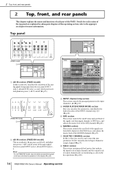
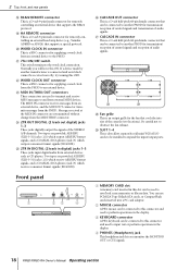
... SELECTED CHANNEL section In this section you can view and control the mix parameters for each part of the PM5D. F MATRIX section This section controls the send level of the signals sent from input channels to the appropriate ... MIX buses, and adjusts the master level of the MIX channels (➥ p.49). Top panel (PM5D model) 1 6 4 5 8 7 A AD IN section (PM5D model) In this section you can select the parameters controlled by the faders/encoders of the INPUT channel...panel are controlled by key operations (➥ p.100). 14 PM5D/PM5D-RH Owner's Manual Operating section
... SELECTED CHANNEL section In this section you can view and control the mix parameters for each part of the PM5D. F MATRIX section This section controls the send level of the signals sent from input channels to the appropriate ... MIX buses, and adjusts the master level of the MIX channels (➥ p.49). Top panel (PM5D model) 1 6 4 5 8 7 A AD IN section (PM5D model) In this section you can select the parameters controlled by the faders/encoders of the INPUT channel...panel are controlled by key operations (➥ p.100). 14 PM5D/PM5D-RH Owner's Manual Operating section
Owner's Manual
Page 15
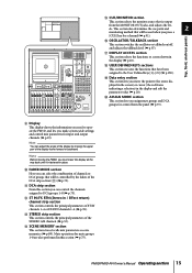
...way back until it is output from the panel (➥ p.73). I Display This display shows the information you need to operate the PM5D, and lets you can control the channels assigned to the User Defined keys [1]-[25] (➥ p.138). Note Before moving the upper part... J FADER MODE section Here you make system-wide settings and control mix parameters for control from the MONITOR OUT jacks, and adjusts the lev- PM5D/PM5D-RH Owner's Manual Operating section 15 8 9 N OP Q JR R K M LT S O CUE/MONITOR section This section selects the monitor source that is fastened...
...way back until it is output from the panel (➥ p.73). I Display This display shows the information you need to operate the PM5D, and lets you can control the channels assigned to the User Defined keys [1]-[25] (➥ p.138). Note Before moving the upper part... J FADER MODE section Here you make system-wide settings and control mix parameters for control from the MONITOR OUT jacks, and adjusts the lev- PM5D/PM5D-RH Owner's Manual Operating section 15 8 9 N OP Q JR R K M LT S O CUE/MONITOR section This section selects the monitor source that is fastened...
Owner's Manual
Page 16
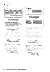
...dBu. Male XLR plug 1 (ground) 3 (cold) 2 (hot) 5 D +48V MASTER switch (PM5D-RH model only) This is -62 dBu to +10 dBu. Male XLR plug 1 (ground) 3 (cold) 2 (hot) 16 PM5D/PM5D-RH Owner's Manual Operating section Male XLR plug 1 (ground) 3 (cold) 2 (hot) B INSERT IN/OUT jacks ...1-48 (PM5D model only) These are balanced XLR-3-31 type input jacks for inserting external effects or dynamics processors...
...dBu. Male XLR plug 1 (ground) 3 (cold) 2 (hot) 5 D +48V MASTER switch (PM5D-RH model only) This is -62 dBu to +10 dBu. Male XLR plug 1 (ground) 3 (cold) 2 (hot) 16 PM5D/PM5D-RH Owner's Manual Operating section Male XLR plug 1 (ground) 3 (cold) 2 (hot) B INSERT IN/OUT jacks ...1-48 (PM5D model only) These are balanced XLR-3-31 type input jacks for inserting external effects or dynamics processors...
Owner's Manual
Page 17
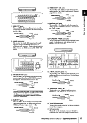
... is an XLR-3-31 (balanced) jack that receives SMPTE time code (LTC) from the channel selected by its [CUE] key. For details, contact your Yamaha dealer. Male XLR plug 1 (ground) 3 (cold) 2 (hot) O TIME CODE INPUT jack This is a four-pin female XLR output jack for... monitor signal selected in the MONITOR section of MATRIX channels 1-8. Use the dedicated cable included with a computer. Q GPI connector This is +4 dBu. PM5D/PM5D-RH Owner's Manual Operating section 17 Female XLR plug 2 (hot) 3 (cold) 1 (ground) Note Although the various output jacks and 2TR IN ANALOG jacks have ...
... is an XLR-3-31 (balanced) jack that receives SMPTE time code (LTC) from the channel selected by its [CUE] key. For details, contact your Yamaha dealer. Male XLR plug 1 (ground) 3 (cold) 2 (hot) O TIME CODE INPUT jack This is a four-pin female XLR output jack for... monitor signal selected in the MONITOR section of MATRIX channels 1-8. Use the dedicated cable included with a computer. Q GPI connector This is +4 dBu. PM5D/PM5D-RH Owner's Manual Operating section 17 Female XLR plug 2 (hot) 3 (cold) 1 (ground) Note Although the various output jacks and 2TR IN ANALOG jacks have ...
Owner's Manual
Page 18
S HA REMOTE connector This is a D-sub 9-pin male connector for remotely controlling an external head amp device (e.g., Yamaha AD8HR or AD824) that can be connected to another PM5D for transmission/ reception of control signals and transmission of audio signals. T WORD CLOCK IN connector This is a BNC connector for ... RS422 protocol. Be careful not to expand the input/output ports. Normally you monitor the MONITOR OUT or CUE signals. 18 PM5D/PM5D-RH Owner's Manual Operating section D PHONES (Headphone) jack This headphone jack lets you will leave this connector and used to the...
S HA REMOTE connector This is a D-sub 9-pin male connector for remotely controlling an external head amp device (e.g., Yamaha AD8HR or AD824) that can be connected to another PM5D for transmission/ reception of control signals and transmission of audio signals. T WORD CLOCK IN connector This is a BNC connector for ... RS422 protocol. Be careful not to expand the input/output ports. Normally you monitor the MONITOR OUT or CUE signals. 18 PM5D/PM5D-RH Owner's Manual Operating section D PHONES (Headphone) jack This headphone jack lets you will leave this connector and used to the...
Owner's Manual
Page 19
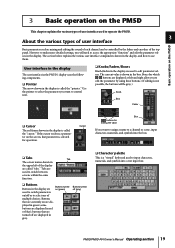
... palette This is selected for operation. The section below explains the various user interface components shown in the display are called "tabs." PM5D/PM5D-RH Owner's Manual Operating section 19 If the cursor encloses a parameter on the screen, that are turned off or to select one of multiple choices... "cursor." However to make more detailed settings, you want to use them. User interface in the display The user interface in the PM5D's display uses the following components. ❏ Pointer The arrow shown in the display is shown in the display. The current value is...
... palette This is selected for operation. The section below explains the various user interface components shown in the display are called "tabs." PM5D/PM5D-RH Owner's Manual Operating section 19 If the cursor encloses a parameter on the screen, that are turned off or to select one of multiple choices... "cursor." However to make more detailed settings, you want to use them. User interface in the display The user interface in the PM5D's display uses the following components. ❏ Pointer The arrow shown in the display is shown in the display. The current value is...
Owner's Manual
Page 20
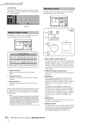
... in that function will appear.) D [ENTER] key Use this to input channels. If you hold down the [SHIFT] key. 20 PM5D/PM5D-RH Owner's Manual Operating section Scroll bar DISPLAY ACCESS section 1 The DISPLAY ACCESS section contains keys that access the desired function or screen in conjunction with the... value will return to the first screen in the display are gathered into a single screen, you will change the parameter value rapidly. If the PM5D has displayed a window asking you turn the [DATA] encoder while holding down the [SHIFT] key and press the [ENTER] key, the JOB...
... in that function will appear.) D [ENTER] key Use this to input channels. If you hold down the [SHIFT] key. 20 PM5D/PM5D-RH Owner's Manual Operating section Scroll bar DISPLAY ACCESS section 1 The DISPLAY ACCESS section contains keys that access the desired function or screen in conjunction with the... value will return to the first screen in the display are gathered into a single screen, you will change the parameter value rapidly. If the PM5D has displayed a window asking you turn the [DATA] encoder while holding down the [SHIFT] key and press the [ENTER] key, the JOB...
Owner's Manual
Page 21
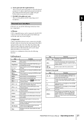
... or select the desired parameter. Function Input a scene number (if the PREFERENCE 1 screen item USE NUMERIC-KEYPAD is on the PM5D External user interface If desired, you operate the track pad. Basic operation on ), same function as the DEL button of 3 headphones... be connected to the KEYBOARD connector located on the front panel of the character palette Same function as the [ENTER] key (when off) PM5D/PM5D-RH Owner's Manual Operating section 21 F Track pad and left button or right track pad button while you can add the following function. Full keyboard Key +...
... or select the desired parameter. Function Input a scene number (if the PREFERENCE 1 screen item USE NUMERIC-KEYPAD is on the PM5D External user interface If desired, you operate the track pad. Basic operation on ), same function as the DEL button of 3 headphones... be connected to the KEYBOARD connector located on the front panel of the character palette Same function as the [ENTER] key (when off) PM5D/PM5D-RH Owner's Manual Operating section 21 F Track pad and left button or right track pad button while you can add the following function. Full keyboard Key +...
Owner's Manual
Page 22
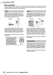
...will simply be called "clicking." Clicking is mainly used to turn an on-screen button on the PM5D Basic operation This section explains the basic procedures you will perform operations in this manual, this operation will simply be performed using the arrow keys and the key. Click Moving the ... in the screen and pressing the left/right track pad button (or the left/ right mouse button) is called "dragging and dropping." 22 PM5D/PM5D-RH Owner's Manual Operating section Drag and drop Moving the mouse pointer to a specific parameter in the screen, dragging to another channel.
...will simply be called "clicking." Clicking is mainly used to turn an on-screen button on the PM5D Basic operation This section explains the basic procedures you will perform operations in this manual, this operation will simply be performed using the arrow keys and the key. Click Moving the ... in the screen and pressing the left/right track pad button (or the left/ right mouse button) is called "dragging and dropping." 22 PM5D/PM5D-RH Owner's Manual Operating section Drag and drop Moving the mouse pointer to a specific parameter in the screen, dragging to another channel.

