
Owner's Manual
Page 2
.... Install in the mains lead of this apparatus during lightning storms or when unused for replacement of the obsolete outlet. 10 Protect the power cord from tip-over. 13 Unplug this apparatus may be connected to the terminal which is necessary either to have "a person who have received appropriate guidance on handling" make the connection or to use leads or a cord...
.... Install in the mains lead of this apparatus during lightning storms or when unused for replacement of the obsolete outlet. 10 Protect the power cord from tip-over. 13 Unplug this apparatus may be connected to the terminal which is necessary either to have "a person who have received appropriate guidance on handling" make the connection or to use leads or a cord...

Owner's Manual
Page 3
... AC outlet, and remove all musical instruments, audio equipment, and speakers when connecting to place heavy objects on vacation, remove the power plug from the following locations: - If some trouble or malfunction occurs, immediately turn the power switch off , remove the power plug from the AC outlet, and contact your dealer. When you think internal inspection, maintenance, or repair is easily accessible. A damaged power cord is a fire...
... AC outlet, and remove all musical instruments, audio equipment, and speakers when connecting to place heavy objects on vacation, remove the power plug from the following locations: - If some trouble or malfunction occurs, immediately turn the power switch off , remove the power plug from the AC outlet, and contact your dealer. When you think internal inspection, maintenance, or repair is easily accessible. A damaged power cord is a fire...
Owner's Manual
Page 4
... follows Pin 1: ground; Follow all installation instructions. Pin 2: hot (+); Illustrations in use only high quality shielded cables. IMPORTANT NOTICE: DO NOT MODIFY THIS UNIT! Always turn the power off when the amplifier is not in this manual, meets FCC requirements. IMPORTANT: When connecting this product MUST be used in this Owner's Manual are trademarks or registered trademarks of a mobile...
... follows Pin 1: ground; Follow all installation instructions. Pin 2: hot (+); Illustrations in use only high quality shielded cables. IMPORTANT NOTICE: DO NOT MODIFY THIS UNIT! Always turn the power off when the amplifier is not in this manual, meets FCC requirements. IMPORTANT: When connecting this product MUST be used in this Owner's Manual are trademarks or registered trademarks of a mobile...

Owner's Manual
Page 5
... offers three operating modes: STEREO (where Channels A and B operate independently), PARALLEL (where the unit outputs a mono source through the manual, please store it in a trim, 2U-sized package. With LOW CUT or SUBWOOFER selected, you for years to come. Contents Controls and Functions 6 Front Panel 6 Rear Panel 7 Speaker Connections 9 Speaker impedance 9 Wiring 10 Rack Mounting 11 Specifications 12 General Specifications 12 Block Diagram 13 Dimensions 14 Current Draw 14 Troubleshooting 15...
... offers three operating modes: STEREO (where Channels A and B operate independently), PARALLEL (where the unit outputs a mono source through the manual, please store it in a trim, 2U-sized package. With LOW CUT or SUBWOOFER selected, you for years to come. Contents Controls and Functions 6 Front Panel 6 Rear Panel 7 Speaker Connections 9 Speaker impedance 9 Wiring 10 Rack Mounting 11 Specifications 12 General Specifications 12 Block Diagram 13 Dimensions 14 Current Draw 14 Troubleshooting 15...

Owner's Manual
Page 6
... occurred because the signal level is corrected, the indicator goes off and normal operation resumes. 4 CLIP indicator Lights up red to 0 dB. Controls and Functions ■ Front Panel 2 4 8 13 576 8 1 POWER switch and indicator Press to toggle the power on the rear panel is set ON. (See page 7.) 8 Air intakes The amplifier uses forced-air cooling. How to install the security cover (1) Use the supplied...
... occurred because the signal level is corrected, the indicator goes off and normal operation resumes. 4 CLIP indicator Lights up red to 0 dB. Controls and Functions ■ Front Panel 2 4 8 13 576 8 1 POWER switch and indicator Press to toggle the power on the rear panel is set ON. (See page 7.) 8 Air intakes The amplifier uses forced-air cooling. How to install the security cover (1) Use the supplied...

Owner's Manual
Page 7
...; Rear Panel 12 5 LOW CUT SUB WOOFER OFF OFF SUB WOOFER LOW CUT 90 50 125 ON OFF 90 50 125 25 Hz 150 STEREO BRIDGE PARALLEL 25 Hz 150 FREQUENCY FREQUENCY INPUT LOCK LOCK SPEAKERS 3 2 23 + 1+ - 1- - 1+ +1- 1+ + 1- - 2+ + 2- - (-) (+) BRIDGE 43 6 1 FILTER switch and FREQUENCY adjustment knob (One pair for each channel) Use these controls to select the filter type and adjust the cutoff frequency on speakers such as the YAMAHA S112 and S115. 3 INPUT jacks (Channels A, B) Two jack types are wired...
...; Rear Panel 12 5 LOW CUT SUB WOOFER OFF OFF SUB WOOFER LOW CUT 90 50 125 ON OFF 90 50 125 25 Hz 150 STEREO BRIDGE PARALLEL 25 Hz 150 FREQUENCY FREQUENCY INPUT LOCK LOCK SPEAKERS 3 2 23 + 1+ - 1- - 1+ +1- 1+ + 1- - 2+ + 2- - (-) (+) BRIDGE 43 6 1 FILTER switch and FREQUENCY adjustment knob (One pair for each channel) Use these controls to select the filter type and adjust the cutoff frequency on speakers such as the YAMAHA S112 and S115. 3 INPUT jacks (Channels A, B) Two jack types are wired...

Owner's Manual
Page 8
... B input jacks do not function. To adjust the volume, you are having a problem with a conventional stereo amplifier). If you must use this switch to the Channel B output jacks. • PARALLEL mode The Channel A input signal is output through both the Channel A and Channel B output jacks. The Channel A input goes to the Channel A output jacks, and the Channel B input goes to select the operating mode. • STEREO mode Channels A and B operate independently (as with hum or noise, use the Channel A volume control knob. 5 SPEAKER jacks Neutrik NL4FC Speakon output connectors...
... B input jacks do not function. To adjust the volume, you are having a problem with a conventional stereo amplifier). If you must use this switch to the Channel B output jacks. • PARALLEL mode The Channel A input signal is output through both the Channel A and Channel B output jacks. The Channel A input goes to the Channel A output jacks, and the Channel B input goes to select the operating mode. • STEREO mode Channels A and B operate independently (as with hum or noise, use the Channel A volume control knob. 5 SPEAKER jacks Neutrik NL4FC Speakon output connectors...
Owner's Manual
Page 9
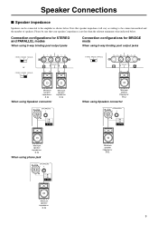
...value indicated below . Please be connected to the connection method and the number of speakers. Connection configurations for STEREO and PARALLEL modes When using 5-way binding post output jacks Connection configurations for BRIDGE mode When using 5-way binding post output jacks STEREO BRIDGE PARALLEL or STEREO BRIDGE PARALLEL - 1+ +1- (-) (+) BRIDGE STEREO BRIDGE PARALLEL - 1+ +1- (-) (+) BRIDGE Minimum speaker impedance: 4 Ω When using phone jack LOCK LOCK SPEAKERS 3 2 23 + 1+ - 1- 1+ + 1- - 2+ + 2- - Minimum speaker impedance: 8 Ω Minimum...
...value indicated below . Please be connected to the connection method and the number of speakers. Connection configurations for STEREO and PARALLEL modes When using 5-way binding post output jacks Connection configurations for BRIDGE mode When using 5-way binding post output jacks STEREO BRIDGE PARALLEL or STEREO BRIDGE PARALLEL - 1+ +1- (-) (+) BRIDGE STEREO BRIDGE PARALLEL - 1+ +1- (-) (+) BRIDGE Minimum speaker impedance: 4 Ω When using phone jack LOCK LOCK SPEAKERS 3 2 23 + 1+ - 1- 1+ + 1- - 2+ + 2- - Minimum speaker impedance: 8 Ω Minimum...

Owner's Manual
Page 10
.... Speakon connector (1) Turn off the POWER switch. (2) Remove the cover attachment screws and remove the pro- Neutrik NL4FC plugs CHANNEL A STEREO or PARALLEL BRIDGE 1+ A+ 1+ + 1- B- 2- Neutrik NL4FC plugs CHANNEL B 1+ B+ 1- 15mm ■ Wiring 5-way binding post (1) Turn off the POWER switch. (2) Insert the Neutrik NL4FC plugs into the jack on the rear of the amplifier, and turn clockwise to lock. tective cover from the speaker terminals. tor on the rear of the...
.... Speakon connector (1) Turn off the POWER switch. (2) Remove the cover attachment screws and remove the pro- Neutrik NL4FC plugs CHANNEL A STEREO or PARALLEL BRIDGE 1+ A+ 1+ + 1- B- 2- Neutrik NL4FC plugs CHANNEL B 1+ B+ 1- 15mm ■ Wiring 5-way binding post (1) Turn off the POWER switch. (2) Insert the Neutrik NL4FC plugs into the jack on the rear of the amplifier, and turn clockwise to lock. tective cover from the speaker terminals. tor on the rear of the...

Owner's Manual
Page 11
..., and when mounting any number of amplifiers in a close-backed rack Install ventilation panels above and below each amplifer. Rack Mounting Mounting in a standard EIA rack If you are mounting multiple power amplifiers in a rack, be sure to use metal brackets (one on each side) to support the rear of each amplifi...
..., and when mounting any number of amplifiers in a close-backed rack Install ventilation panels above and below each amplifer. Rack Mounting Mounting in a standard EIA rack If you are mounting multiple power amplifiers in a rack, be sure to use metal brackets (one on each side) to support the rear of each amplifi...

Owner's Manual
Page 12
... Volume control knobs (one per ch) Rear Panel MODE switch (STEREO/PARALLEL/BRIDGE) Two FILTER switches (SUBWOOFER/LOW CUT/OFF) Two fc knobs (25 to 150 Hz, 12 dB/octave) YS Processing switch (ON/OFF) Connectors INPUT XLR-3-31 jacks (one per ch) 1/4-inch TRS phone jacks (one per ch) OUTPUT Speakon jacks (one per ch) 5-way binding posts 1/4-inch phone jacks (one per ch) Indicators POWER × 1 (Green) PROTECTION...
... Volume control knobs (one per ch) Rear Panel MODE switch (STEREO/PARALLEL/BRIDGE) Two FILTER switches (SUBWOOFER/LOW CUT/OFF) Two fc knobs (25 to 150 Hz, 12 dB/octave) YS Processing switch (ON/OFF) Connectors INPUT XLR-3-31 jacks (one per ch) 1/4-inch TRS phone jacks (one per ch) OUTPUT Speakon jacks (one per ch) 5-way binding posts 1/4-inch phone jacks (one per ch) Indicators POWER × 1 (Green) PROTECTION...

Owner's Manual
Page 14
■ Dimensions ■ Current Draw P7000S standby idle 1/8 power 8Ω/ch 4Ω/ch 1/3 power 8Ω/ch 4Ω/ch P5000S standby idle 1/8 power 8Ω/ch 4Ω/ch 1/3 power 8Ω/ch 4Ω/ch P3500S standby idle 1/8 power 8Ω/ch 4Ω/ch 1/3 power 8Ω/ch 4Ω/ch Line Current (A) 100/120V 230/240V 0.08 0.04 1.0 0.5 5.4 3.0 8.5 4.7 12.8 7.0 20.6 11.3 Line Current (A) 100/120V 230/240V...
■ Dimensions ■ Current Draw P7000S standby idle 1/8 power 8Ω/ch 4Ω/ch 1/3 power 8Ω/ch 4Ω/ch P5000S standby idle 1/8 power 8Ω/ch 4Ω/ch 1/3 power 8Ω/ch 4Ω/ch P3500S standby idle 1/8 power 8Ω/ch 4Ω/ch 1/3 power 8Ω/ch 4Ω/ch Line Current (A) 100/120V 230/240V 0.08 0.04 1.0 0.5 5.4 3.0 8.5 4.7 12.8 7.0 20.6 11.3 Line Current (A) 100/120V 230/240V...

Owner's Manual
Page 15
... amplifier. The thermal protection circuit operates to indicate temperature warning. Consult your dealer or the nearest Yamaha service center. PROTECTION indicator lights. P3500S, P2500S Indicator(s) PROTECTION indicator lights. The amplifier load is a short at least 4 Ω (STEREO/PARALLEL mode) or 8 Ω (BRIDGE mode). Consult your dealer or the nearest Yamaha service center. P2500S standby idle 1/8 power 8Ω/ch 4Ω/ch 1/3 power 8Ω/ch 4Ω/ch...
... amplifier. The thermal protection circuit operates to indicate temperature warning. Consult your dealer or the nearest Yamaha service center. PROTECTION indicator lights. P3500S, P2500S Indicator(s) PROTECTION indicator lights. The amplifier load is a short at least 4 Ω (STEREO/PARALLEL mode) or 8 Ω (BRIDGE mode). Consult your dealer or the nearest Yamaha service center. P2500S standby idle 1/8 power 8Ω/ch 4Ω/ch 1/3 power 8Ω/ch 4Ω/ch...

Owner's Manual
Page 16
... 91-639-8888 SWEDEN Yamaha Scandinavia AB J. Wettergrens Gata 1, Box 30053 S-400 43 G&#...Yamaha Musica Italia S.P.A. Taiwan 104, R.O.C. NORTH AMERICA CANADA Yamaha Canada Music Ltd. 135 Milner Avenue, Scarborough, Ontario, M1S 3R1, Canada Tel: 416-298-1311 U.S.A. Calz. Nusantik Gedung Yamaha Music Center...Yamaha Pro Audio global web site http://www.yamahaproaudio.com/ Yamaha Manual Library http://www.yamaha.co.jp/manual/ U.R.G., Pro Audio & Digital Musical Instrument Division, Yamaha Corporation © 2003 Yamaha Corporation WB09700 001CRZCx.x-xxE0 Printed in Indonesia Yamaha Music...
... 91-639-8888 SWEDEN Yamaha Scandinavia AB J. Wettergrens Gata 1, Box 30053 S-400 43 G&#...Yamaha Musica Italia S.P.A. Taiwan 104, R.O.C. NORTH AMERICA CANADA Yamaha Canada Music Ltd. 135 Milner Avenue, Scarborough, Ontario, M1S 3R1, Canada Tel: 416-298-1311 U.S.A. Calz. Nusantik Gedung Yamaha Music Center...Yamaha Pro Audio global web site http://www.yamahaproaudio.com/ Yamaha Manual Library http://www.yamaha.co.jp/manual/ U.R.G., Pro Audio & Digital Musical Instrument Division, Yamaha Corporation © 2003 Yamaha Corporation WB09700 001CRZCx.x-xxE0 Printed in Indonesia Yamaha Music...


