Yamaha A-S2000 - Amplifier Support and Manuals
Get Help and Manuals for this Yamaha item
View All Support Options Below
Free Yamaha A-S2000 manuals!
Problems with Yamaha A-S2000?
Ask a Question
Free Yamaha A-S2000 manuals!
Problems with Yamaha A-S2000?
Ask a Question
Yamaha A-S2000 Videos

Elac BS244 + Yamaha A-S2000 + NAD C 565BEE
Duration: :40
Total Views: 6,228
Duration: :40
Total Views: 6,228
Yamaha A-S2000 Rega P3-24 Turntable
Duration: 6:35
Total Views: 7,153
Duration: 6:35
Total Views: 7,153
Yamaha a-s2000 test
Duration: 3:31
Total Views: 7,427
Duration: 3:31
Total Views: 7,427
Yamaha A-S2000
Duration: 5:08
Total Views: 4,336
Duration: 5:08
Total Views: 4,336
Popular Yamaha A-S2000 Manual Pages
Service Manual - Page 1

..., and more specifically YAMAHA Products, are continually striving to the unit(s) indicated on the cover.
IMPORTANT: The presentation or sale of this buss).
I CONTENTS
TO SERVICE PERSONNEL 2 FRONT PANEL 2 REAR PANELS 3-5 REMOTE CONTROL PANELS 6 SPECIFICATIONS 7 INTERNAL VIEW 8 SERVICE PRECAUTIONS 9 DISASSEMBLY PROCEDURES 9-18 AMP ADJUSTMENT 19-20 UPDATING FIRMWARE 21-27
SELF...
Service Manual - Page 2

...Models Only) When service has been completed, it is recommended to use a soldering iron suitable to verify that of the lead solder, be sure to those originally installed.
2.
I TO SERVICE PERSONNEL
1.
G Be sure to test for the repair... Information Components having specifications equal to use ...Meter impedance should be replaced with parts having special characteristics are...
Service Manual - Page 7

A-S2000
I SPECIFICATIONS
I General / ૯߹ Power Supply
U, C models AC 120 V, 60 Hz R, L models AC 110/120/220/230-240 V, 50/60 Hz T model AC 220 V, 50 Hz K model AC 220 V, 60 Hz A model AC 240 V, 50 Hz B, G models AC 230 V, 50 Hz J model AC 100 V, 50/60 Hz Power Consumption U, C, R, T, K, A, B, G, L models 350 W J model 220 W Idling Power Consumption 80 W Off-state Power...
Service Manual - Page 9

... TC unit. (Fig. 1)
d. Front panel
Lock set screw to cause damage the switches. (Fig. 1)
NN
B 70 JHʣ
C 4 JHʣ
D 5 JHʣ
E 6 JHʣ F ʠ108&30/0 0/ʹ͠·͢ɻ G ʠ1)0/0 H
JHʣ
A-S2000
* When installing the knob unit, it is about 30 seconds.
1. Before starting any repair work, perform discharge by connecting...
Service Manual - Page 10

...in that it matches with its lock set screw. G When installing the knob TC unit
* Use the same installation procedure for BASS,
TREBLE and BALANCE.
Install the knob SEL unit with the "BALANCE.... 2)
d. A-S2000
G When installing the knob VOL unit:
a. Match the slit in the knob VOL unit with the "VOLUME MIN" position and install it is installation of BALANCE and install it matches with...
Service Manual - Page 18

... CB305. (Fig. 10) c. Remove the cable (W3004) from the bottom. (Fig. 11) d.
CB305
U FUNCTION (1) P.C.B. Remove FUNCTION (1) P.C.B and FRONT (10) P.C.B.
S
T S
Support PRE R αϙʔτ13&3
S S
Fig. 10
Bottom view
A-S2000
W3004
Fig. 11 18 and FRONT (10) P.C.B. A-S2000
10. Remove 9 screws (S), a screw (T), and 2 screws (U). (Fig. 10)
b. together with the...
Service Manual - Page 20

R ch
VR102
L ch DC -2.0 to +2.0 mV
20
Fig. 2
PHONES
MAIN (2) P.C.B. R ch L ch DC -2.0 to +2.0 mV
R ch
L ch
VR202
FRONT (2) P.C.B. A-S2000
G Headphone DC Offset Adjustment
Condition • Start adjustment 5 sec or more after the power is
turned on. • No input signal. • Non loaded condition
DC ...
Service Manual - Page 26
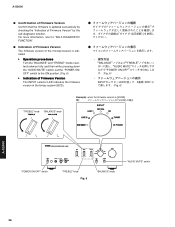
... the "BALANCE" and "TREBLE" knobs counterclockwise fully and then while pressing down the "AUDIO MUTE" switch, set the "POWER ON/ OFF" switch to "SELF-DIAGNOSTIC FUNCTION".
A-S2000
G Confirmation of Firmware Version Confirm that the firmware is [V0035]
ྫʣ
7
A-S2000
"POWER ON/OFF" switch
"TREBLE" knob Fig. 6
"BALANCE" knob
"AUDIO MUTE" switch
26 For more...
Service Manual - Page 28
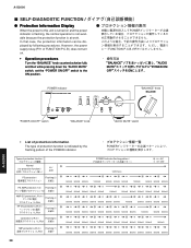
...and then while pressing down the "AUDIO MUTE" switch, set the "POWER ON/OFF" switch to this unit is turned...protection 1/2 / Flashing 3
AMP DC protection L/R ch /
3DI
Flashing 4
HP DC protection L/R ch /
Flashing 5 /
3DI
໓
I SELF-...;͢ɻ
POWER indicator
"BALANCE" knob
A-S2000
"POWER ON/OFF" switch
"BALANCE" knob
"AUDIO MUTE" switch
• List...
Service Manual - Page 29

...trouble shoot, it is not possible to 1.550V
Detection port : THML (FRONT P.C.B. 1 pin of
microprocessor IC502)
THMR (FRONT P.C.B. 64 pin of
microprocessor IC502)
Detected at : PSVA1 (CB24 and CB26 of
power transformer...ʣ
A-S2000
• TMP protection L/Rch
Cause
: Abnormal temperature of heat
sink
Normal value : 0.200 to start this unit with a failure un-repaired and
the ...
Service Manual - Page 34

I Detect head phone insert, H: HP non inserted / L: HP inserted I Balance gain select SW I Detect laver SW for MUTE I Detect laver MMMC, Hi: MC / ...O Initial clear extecded IC I
BASS volume AD TREBLE volume AD COM out Function selector rotary SW AD MAIN VOLUME AD
A-S2000
34 A-S2000
IC504: LC709004A (FRONT P.C.B.) Serial parameter extension
Pin
Port Name
No.
24 P00 23 P01 22 P02 21 P03 20 P04...
Service Manual - Page 37

... • See page 64-66 →
SCHEMATIC DIAGRAM
SPEAKER DRIVER
HOT (POSITIVE PHASE) SIDE
SPCH A L/R CH RY201/R111
SPCH...
BALANCE UNBALANCE CONVERTER
HP END LOW IMPEDANCE DRIVE
HEADPHONE AMP. RY_HP
RY_BAL.../-B4
HPTRIM 14 SP_AB 15
3,4
9-11
SUB-TRANSFORMER
T1
D304
D336
for COLD
6
(for POWER AMP...F
G
H
I
J
A-S2000
1 I BLOCK DIAGRAM
BALANCE • See page 59 →
SCHEMATIC DIAGRAM...
Service Manual - Page 48

...S2000
1
MAIN (2) P.C.B. (Side A)
2
3
INLAGND
INL+
FUNCTION (2)
(CB406)
4
LSP_P LSP_N
5 FRONT (13)
(W201A, W201B)
CB84 W202
MAIN (1) (CB54)
-B4 +B4 +B3 -B3 +PB AGND AGND -PB RIDL2_P RIDL2_N
MAIN (3)
(W315)
IC202
CB72
MAIN (1) (CB55)
CB75
CB78
CB80
CB74 CB77
CB79
#
6
MAIN (5) P.C.B. (Side A)
7 48
#
#
#
#
#
Note) Those parts...
MAIN (1)
(W104)
HP GND HP GND HP GND
MAIN (3)
(W318...
Service Manual - Page 50

... safety measures during servicing, such as wearing insulating gloves.
• Note that positions indicated below are dangerous. A
B
A-S2000
1
MAIN (3) P.C.B. (Side A)
2
3
POWER TRANSFORMER
Blue Brown Black Red
RED Black RED
4
POWER TRANSFORMER
5
HP GND HP GND HP GND
MAIN (2)
(CB52)
6
7 50
W316 W314
W315 W318
C
D
E
F
G
H
I
J
Safety measures
• Some internal parts in this...
Service Manual - Page 67

...be replaced with parts having specifications equal to those originally installed.
SURG...CHP : CHIP DIGITAL TRANSISTOR
TRANS
: TRANSFORMER
TRANS.PULS : PULSE TRANSFORMER
TRANS.PWR : POWER TRANSFORMER ASS'Y
TUNER.AM : TUNER PACK,AM...
PHOT.INTR : PHOTO INTERRUPTER
PHOT.RFLCT : PHOTO REFLECTOR
PIN.TEST : PIN,TEST POINT
PLST.RIVET : PLASTIC RIVET
R.ARRAY : RESISTOR ARRAY
R....SUPPORT,P.C.B.
Yamaha A-S2000 Reviews
We have not received any reviews for Yamaha yet.