
Owner's Manual
Page 2
... plug. * This applies only to products distributed by YAMAHA KEMBLE MUSIC (U.K.) LTD. VARNING : OSYNLIG LASERSTRÅLNING NÄR DENNA DEL ÄR ÖPPNAD. IMPORTANT Please record the serial number of this apparatus may not correspond with the coloured markings identifying the terminals in harmful interference with these corrective measures do not have this product in to eliminate the problem...
... plug. * This applies only to products distributed by YAMAHA KEMBLE MUSIC (U.K.) LTD. VARNING : OSYNLIG LASERSTRÅLNING NÄR DENNA DEL ÄR ÖPPNAD. IMPORTANT Please record the serial number of this apparatus may not correspond with the coloured markings identifying the terminals in harmful interference with these corrective measures do not have this product in to eliminate the problem...
Owner's Manual
Page 5
Important 5 • Turn off all musical instruments, audio equipment, and speakers when connecting to this unit. A damaged power cord is a potential electrical shock hazard. • Do not raise the volume of their respective holders. Operating Notes • The digital circuits of components with wet hands. If noise occurs, relocate the affected equipment. • XLR-type connectors are wired as follows: pin 1: ground, pin...
Important 5 • Turn off all musical instruments, audio equipment, and speakers when connecting to this unit. A damaged power cord is a potential electrical shock hazard. • Do not raise the volume of their respective holders. Operating Notes • The digital circuits of components with wet hands. If noise occurs, relocate the affected equipment. • XLR-type connectors are wired as follows: pin 1: ground, pin...
Owner's Manual
Page 6
... Basic operation 25 Before you begin 25 Example connections 25 Turning on the MD4S 26 Inserting a disc 26 Recording the first track (Direct Recording 26 Preparations for recording 26 Start recording 28 Overdubbing 30 Mixdown ...32 After completing the Basic Operation section 34 Advanced recording techniques 35 Advanced techniques on the MD4S 35 Mixing multiple channels as you record 36 Ping-pong recording 39 Adding sounds during mixdown 42 -Owner's Manual
... Basic operation 25 Before you begin 25 Example connections 25 Turning on the MD4S 26 Inserting a disc 26 Recording the first track (Direct Recording 26 Preparations for recording 26 Start recording 28 Overdubbing 30 Mixdown ...32 After completing the Basic Operation section 34 Advanced recording techniques 35 Advanced techniques on the MD4S 35 Mixing multiple channels as you record 36 Ping-pong recording 39 Adding sounds during mixdown 42 -Owner's Manual
Owner's Manual
Page 7
... Erasing a disc (Disc Erase 86 Viewing disc contents 86 Changing the recording mode 87 Adjusting the display brightness 88 Selecting the type of Frame display 88 Using a Foot switch 89 MIDI functions 90 Synchronizing the MD4S with a MIDI sequencer 90 About MTC and MIDI Clock 91 Synchronization using MTC 91 Synchronization using MIDI Clock 92 Synchronizing two MD4S recorders 94 Synchronizing to MTC with a specified offset (time difference 97 Controlling the MD4S by MMC 98 -Owner's Manual
... Erasing a disc (Disc Erase 86 Viewing disc contents 86 Changing the recording mode 87 Adjusting the display brightness 88 Selecting the type of Frame display 88 Using a Foot switch 89 MIDI functions 90 Synchronizing the MD4S with a MIDI sequencer 90 About MTC and MIDI Clock 91 Synchronization using MTC 91 Synchronization using MIDI Clock 92 Synchronizing two MD4S recorders 94 Synchronizing to MTC with a specified offset (time difference 97 Controlling the MD4S by MMC 98 -Owner's Manual
Owner's Manual
Page 9
Recorder The recorder features a 4-track recorder based on input channels 1-4, accepting signals ranging from mic input to line level. • Of the four MIC/LINE inputs, two are provided for direct output of the playback from each track, you can make full use of either TRS phone plugs or XLR plugs. • Input channels 1 and 2 provide INSERT I/O jacks that allow external effects such as a compressor to be connected. • Input channels 1-4 provide three-band EQ (HIGH/MID/LOW) that...
Recorder The recorder features a 4-track recorder based on input channels 1-4, accepting signals ranging from mic input to line level. • Of the four MIC/LINE inputs, two are provided for direct output of the playback from each track, you can make full use of either TRS phone plugs or XLR plugs. • Input channels 1 and 2 provide INSERT I/O jacks that allow external effects such as a compressor to be connected. • Input channels 1-4 provide three-band EQ (HIGH/MID/LOW) that...
Owner's Manual
Page 17
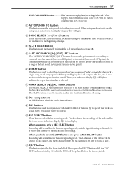
... the REC SELECT buttons J to update the TOC (page 11). The repeat indicator (display O) will light. When auto punch-in/out is lit, the TOC will be sent directly to tracks 2 and 4. B AUTO PUNCH I BUS button This button is ejected. -Owner's Manual H Disc compartment An MD DATA or MiniDisc can set at which the ST bus signal will be recorded. Front and rear panel 17 STOP/TOC WRITE button This button stops playback/recording/rehearsal...
... the REC SELECT buttons J to update the TOC (page 11). The repeat indicator (display O) will light. When auto punch-in/out is lit, the TOC will be sent directly to tracks 2 and 4. B AUTO PUNCH I BUS button This button is ejected. -Owner's Manual H Disc compartment An MD DATA or MiniDisc can set at which the ST bus signal will be recorded. Front and rear panel 17 STOP/TOC WRITE button This button stops playback/recording/rehearsal...
Owner's Manual
Page 18
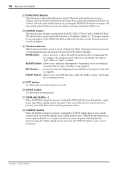
..., rotating the CURSOR shuttle allows you to cancel a function or mode. N Function buttons These buttons are used to the setting, the pitch indicator in frame steps. UTILITY button... According to select parameters. -Owner's Manual When editing various functions (when one of speeds (Shuttle playback functions: page 66). R CURSOR shuttle When the MD4S is stopped or paused, rotating the DATA dial will switch the time counter between measure/ beat/clock displays. EDIT button ........
..., rotating the CURSOR shuttle allows you to cancel a function or mode. N Function buttons These buttons are used to the setting, the pitch indicator in frame steps. UTILITY button... According to select parameters. -Owner's Manual When editing various functions (when one of speeds (Shuttle playback functions: page 66). R CURSOR shuttle When the MD4S is stopped or paused, rotating the DATA dial will switch the time counter between measure/ beat/clock displays. EDIT button ........
Owner's Manual
Page 19
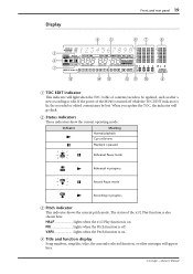
... indicators show the current operating mode. Indicator Meaning Normal playback Cue or Review Playback is on . VARI Lights when the Pitch function is paused REHE Rehearsal Pause mode Rehearsal in progress REHE REC Record Pause mode REC Recording in progress C Pitch indicator This indicator shows the current pitch mode. The status of contents) needs to be lost. When you update the TOC, the indicator will appear here. -Owner's Manual D Title and function display Song numbers, song/disc...
... indicators show the current operating mode. Indicator Meaning Normal playback Cue or Review Playback is on . VARI Lights when the Pitch function is paused REHE Rehearsal Pause mode Rehearsal in progress REHE REC Record Pause mode REC Recording in progress C Pitch indicator This indicator shows the current pitch mode. The status of contents) needs to be lost. When you update the TOC, the indicator will appear here. -Owner's Manual D Title and function display Song numbers, song/disc...
Owner's Manual
Page 21
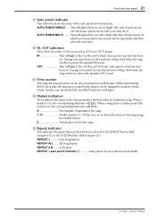
... indicator This indicates the repeat function that has been selected by the REPEAT button (disk transport 6, or the A B button (disk transport 4). When a song passes a marker point that has been set . REPEAT 1 One Song Repeat REPEAT ALL ....... AUTO PUNCH MULTI ......... M Time counter This indicates time locations on the disc in the song using the MARK button. AUTO PUNCH SINGLE....... OUT This will light if the Last Record...
... indicator This indicates the repeat function that has been selected by the REPEAT button (disk transport 6, or the A B button (disk transport 4). When a song passes a marker point that has been set . REPEAT 1 One Song Repeat REPEAT ALL ....... AUTO PUNCH MULTI ......... M Time counter This indicates time locations on the disc in the song using the MARK button. AUTO PUNCH SINGLE....... OUT This will light if the Last Record...
Owner's Manual
Page 23
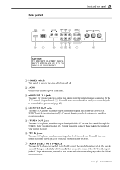
... to use an external mixer to mix the playback of your hi-fi system or to the inputs of the ST bus that output the monitor signal selected by the AUX controls (input channel 5). Normally they are connected to turn the MD4S on and off. B AC IN Connect the included power cable here. D MONITOR OUT jacks These are used to the output jacks of the MD4S recorder tracks. -Owner's Manual A POWER switch This switch is used as adjusted by...
... to use an external mixer to mix the playback of your hi-fi system or to the inputs of the ST bus that output the monitor signal selected by the AUX controls (input channel 5). Normally they are connected to turn the MD4S on and off. B AC IN Connect the included power cable here. D MONITOR OUT jacks These are used to the output jacks of the MD4S recorder tracks. -Owner's Manual A POWER switch This switch is used as adjusted by...
Owner's Manual
Page 26
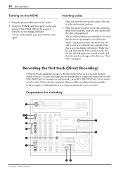
...7 7 7 6 6 6 6 5 5 5 5 4 4 4 4 3 3 3 3 2 2 2 2 1 1 1 1 0 0 0 0 MONITOR LEVEL MIN 10 9 8 7 6 5 4 3 2 1 0 MAX 10 9 8 7 6 5 4 3 2 1 0 1 2 3 4 STEREO REPEAT MARK SEARCH AB AUTO PUNCH I/O LAST REC SEARCH IN OUT SONG SEARCH REHE REC PLAY MARK SET PAUSE STOP TOC WRITE CH1 1 L REC SELECT CH2 CH3 2 3 R L CH4 4 R EJECT PEAK HOLD DISPLAY PITCH ADJUST EDIT UTILITY EXIT ENTER DATA CURSOR PHONES PUNCH I/O 51 -Owner's Manual 4 9 26 Basic operation Turning on the disc (e.g., "Total 004") will appear. Inserting a disc Make sure that...
...7 7 7 6 6 6 6 5 5 5 5 4 4 4 4 3 3 3 3 2 2 2 2 1 1 1 1 0 0 0 0 MONITOR LEVEL MIN 10 9 8 7 6 5 4 3 2 1 0 MAX 10 9 8 7 6 5 4 3 2 1 0 1 2 3 4 STEREO REPEAT MARK SEARCH AB AUTO PUNCH I/O LAST REC SEARCH IN OUT SONG SEARCH REHE REC PLAY MARK SET PAUSE STOP TOC WRITE CH1 1 L REC SELECT CH2 CH3 2 3 R L CH4 4 R EJECT PEAK HOLD DISPLAY PITCH ADJUST EDIT UTILITY EXIT ENTER DATA CURSOR PHONES PUNCH I/O 51 -Owner's Manual 4 9 26 Basic operation Turning on the disc (e.g., "Total 004") will appear. Inserting a disc Make sure that...
Owner's Manual
Page 27
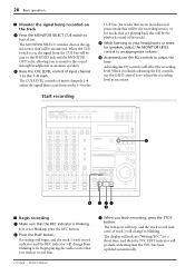
... PEAK HOLD button, refer to page 18. -Owner's Manual The track recording indicator (DIR) for track 1 will indicate about -3 for more information.) Tip: If you set the FLIP switch to the "MIC/LINE ( )" position, the input signal from input channel 1 will be shown when you will indicate "BLANK X" (where X is important to set the display time counter mode to REMAIN TIME, the length of available recording time for consecutive recording may be recorded (001), and...
... PEAK HOLD button, refer to page 18. -Owner's Manual The track recording indicator (DIR) for track 1 will indicate about -3 for more information.) Tip: If you set the FLIP switch to the "MIC/LINE ( )" position, the input signal from input channel 1 will be shown when you will indicate "BLANK X" (where X is important to set the display time counter mode to REMAIN TIME, the length of available recording time for consecutive recording may be recorded (001), and...
Owner's Manual
Page 28
... be the playback sound of input channels 1-4 adjust the signal that will be sent to the PHONES jack and the MONITOR OUT jacks, allowing you to monitor the sound through headphones or monitor speakers. 0 Raise the CUE LEVEL control of track 1 will change from the CUE bus will be monitored. When you finish recording, press the STOP button. The CUE LEVEL controls of the track). Begin playing the audio source that...
... be the playback sound of input channels 1-4 adjust the signal that will be sent to the PHONES jack and the MONITOR OUT jacks, allowing you to monitor the sound through headphones or monitor speakers. 0 Raise the CUE LEVEL control of track 1 will change from the CUE bus will be monitored. When you finish recording, press the STOP button. The CUE LEVEL controls of the track). Begin playing the audio source that...
Owner's Manual
Page 29
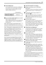
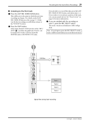
... first track (Direct Recording) 29 s Listening to re-record just a portion of track 1 can be erased when you can use punch-in the "MIC/ LINE ( )" position, the playback of the track, you record the next track. 1 GAIN LINE MIC MIC/ LINE PB CUE FLIP P A N L R 0 HIGH L E V E L 10 -15 +15 MID -15 +15 LOW -15 +15 AUX 1 2 PAN L R 10 9 8 7 6 5 4 3 2 1 0 CUE Bus MONITOR OUT L PHONES R Track 1 Track 2 Track 3 Track 4 Signal flow during track recording -Owner's Manual
... first track (Direct Recording) 29 s Listening to re-record just a portion of track 1 can be erased when you can use punch-in the "MIC/ LINE ( )" position, the playback of the track, you record the next track. 1 GAIN LINE MIC MIC/ LINE PB CUE FLIP P A N L R 0 HIGH L E V E L 10 -15 +15 MID -15 +15 LOW -15 +15 AUX 1 2 PAN L R 10 9 8 7 6 5 4 3 2 1 0 CUE Bus MONITOR OUT L PHONES R Track 1 Track 2 Track 3 Track 4 Signal flow during track recording -Owner's Manual
Owner's Manual
Page 30
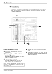
... LEVEL MIN 10 9 8 7 6 5 4 3 2 1 0 MAX 10 9 8 7 6 5 4 3 2 1 0 1 2 3 4 STEREO REPEAT MARK SEARCH AB AUTO PUNCH I/O LAST REC SEARCH IN OUT SONG SEARCH REHE REC PLAY MARK SET PAUSE STOP TOC WRITE CH1 1 L REC SELECT CH2 CH3 2 3 R L CH4 4 R EJECT PEAK HOLD DISPLAY PITCH ADJUST EDIT UTILITY EXIT ENTER DATA CURSOR PHONES PUNCH I/O 5 8 47 9 30 s Select the track to record 1 Connect the audio source to MIC/LINE INPUT jack 2. 2 Set the input channel 2 FLIP switch to record. The...
... LEVEL MIN 10 9 8 7 6 5 4 3 2 1 0 MAX 10 9 8 7 6 5 4 3 2 1 0 1 2 3 4 STEREO REPEAT MARK SEARCH AB AUTO PUNCH I/O LAST REC SEARCH IN OUT SONG SEARCH REHE REC PLAY MARK SET PAUSE STOP TOC WRITE CH1 1 L REC SELECT CH2 CH3 2 3 R L CH4 4 R EJECT PEAK HOLD DISPLAY PITCH ADJUST EDIT UTILITY EXIT ENTER DATA CURSOR PHONES PUNCH I/O 5 8 47 9 30 s Select the track to record 1 Connect the audio source to MIC/LINE INPUT jack 2. 2 Set the input channel 2 FLIP switch to record. The...
Owner's Manual
Page 46
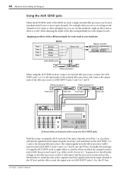
... MD RECORDER CH1 1 L REC SELECT CH2 CH3 2 3 R L CH4 4 R EJECT PEAK HOLD DISPLAY PITCH ADJUST EDIT UTILITY External effect connections when using the AUX SEND jacks to connect an external effect processor, connect the AUX SEND jacks 1 or 2 to the input jacks of the external effect processor, and connect the output jacks of the effect processor to LINE INPUT jacks 5 and 6 or 7 and 8. The output signals from the input channels (in which the original sound is used...
... MD RECORDER CH1 1 L REC SELECT CH2 CH3 2 3 R L CH4 4 R EJECT PEAK HOLD DISPLAY PITCH ADJUST EDIT UTILITY External effect connections when using the AUX SEND jacks to connect an external effect processor, connect the AUX SEND jacks 1 or 2 to the input jacks of the external effect processor, and connect the output jacks of the effect processor to LINE INPUT jacks 5 and 6 or 7 and 8. The output signals from the input channels (in which the original sound is used...
Owner's Manual
Page 48
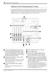
... STOP TOC WRITE CH1 1 L REC SELECT CH2 CH3 2 3 R L CH4 4 R EJECT PEAK HOLD DISPLAY PITCH ADJUST EDIT UTILITY EXIT ENTER DATA CURSOR PHONES PUNCH I/O 45 0 7 2 3 6 1 Connect the AUX SEND 1 jack to the input jack of the effect processor to set the recording level. (At the ideal level, the -3 segment will light when peaks occur.) -Owner's Manual The following will blink. Make sure that the track record indicators for tracks 1 and 2 are dark. 3 Turn...
... STOP TOC WRITE CH1 1 L REC SELECT CH2 CH3 2 3 R L CH4 4 R EJECT PEAK HOLD DISPLAY PITCH ADJUST EDIT UTILITY EXIT ENTER DATA CURSOR PHONES PUNCH I/O 45 0 7 2 3 6 1 Connect the AUX SEND 1 jack to the input jack of the effect processor to set the recording level. (At the ideal level, the -3 segment will light when peaks occur.) -Owner's Manual The following will blink. Make sure that the track record indicators for tracks 1 and 2 are dark. 3 Turn...
Owner's Manual
Page 50
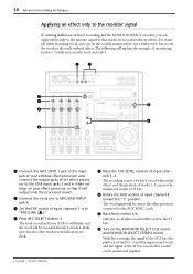
.... 5 Raise the CUE LEVEL controls of input channels 1-4. Make settings on your external effect processor, and connect the output jacks of input channels 1-4 to track 4. The vocal signal will be monitored together. -Owner's Manual Make sure that it will explain the example of monitoring tracks 1-3 while you record a vocal on the MONITOR SELECT CUE switch and MONITOR SELECT STEREO switch. With these settings, the signal of the CUE bus (the playback of tracks 1-3 and the unprocessed...
.... 5 Raise the CUE LEVEL controls of input channels 1-4. Make settings on your external effect processor, and connect the output jacks of input channels 1-4 to track 4. The vocal signal will be monitored together. -Owner's Manual Make sure that it will explain the example of monitoring tracks 1-3 while you record a vocal on the MONITOR SELECT CUE switch and MONITOR SELECT STEREO switch. With these settings, the signal of the CUE bus (the playback of tracks 1-3 and the unprocessed...

Owner's Manual
Page 101
... your MD4S, contact your Yamaha dealer. If the FLIP switch is in point. -Owner's Manual Up to a connected music source! Make sure that the x1/2 Play function is connected to a suitable AC wall outlet and plugged into the AC IN connector at a location that the 4TR recording mode is ready to record. Make sure that the MONITOR LEVEL control is set at the rear of the corresponding input channel and the STEREO...
... your MD4S, contact your Yamaha dealer. If the FLIP switch is in point. -Owner's Manual Up to a connected music source! Make sure that the x1/2 Play function is connected to a suitable AC wall outlet and plugged into the AC IN connector at a location that the 4TR recording mode is ready to record. Make sure that the MONITOR LEVEL control is set at the rear of the corresponding input channel and the STEREO...
Owner's Manual
Page 108
... MD4S" on page 26. Foot switch-A foot operated switch. After a signal is input to an input channel, it is sent through the EQ to adjust its tone, its own output jack. MD DATA-A compact data storage medium designed to the Cue bus, and output from the AUX OUT jacks. See "Buying discs for playback) using the Cue List Copy function. ATRAC-An acronym for Digital Audio Tape. This is the compression technique used...
... MD4S" on page 26. Foot switch-A foot operated switch. After a signal is input to an input channel, it is sent through the EQ to adjust its tone, its own output jack. MD DATA-A compact data storage medium designed to the Cue bus, and output from the AUX OUT jacks. See "Buying discs for playback) using the Cue List Copy function. ATRAC-An acronym for Digital Audio Tape. This is the compression technique used...


