

DME7 Reference Manual
Page 2
... About Yamaha Steinberg USB Driver 5 Updating the firmware 5 Precautions for rack mounting 6 Part names and functions 7 Front panel 7 Rear panel 9 Making connections 12 Connecting to the [GPI] ports 12 Connecting a Euroblock plug 12 Installing the cable hook 14 About Dante 15 About connection 16 Power supply 19 Connecting the power supply 19 Switching on/off this device 19 Panel operation 20 Basic operations 20 Muting/Unmuting (Device Mute screen 21 Enabling/disabling the control function (Control Function screen 22 Alert screen 22 Panel lock 22 Screens 24 Home screen 24...
... About Yamaha Steinberg USB Driver 5 Updating the firmware 5 Precautions for rack mounting 6 Part names and functions 7 Front panel 7 Rear panel 9 Making connections 12 Connecting to the [GPI] ports 12 Connecting a Euroblock plug 12 Installing the cable hook 14 About Dante 15 About connection 16 Power supply 19 Connecting the power supply 19 Switching on/off this device 19 Panel operation 20 Basic operations 20 Muting/Unmuting (Device Mute screen 21 Enabling/disabling the control function (Control Function screen 22 Alert screen 22 Panel lock 22 Screens 24 Home screen 24...

DME7 Reference Manual
Page 3
... settings (Initialize Settings 37 Restarting (Reboot 37 Snapshot Recall 38 Restoring factory default settings (initializing 39 Method of selecting [Settings] > [Initialize Settings 39 If you have forgotten your administrator PIN 40 Appendix 41 Precautions for the USB port 41 Using USB flash drives 41 Precautions for using SD memory cards 42 Using SD memory cards 42 Distance to furthest DCP control panel 43 Message List 44 General specifications 50 Dimensions 52 Block diagram 53 2 | DME7...
... settings (Initialize Settings 37 Restarting (Reboot 37 Snapshot Recall 38 Restoring factory default settings (initializing 39 Method of selecting [Settings] > [Initialize Settings 39 If you have forgotten your administrator PIN 40 Appendix 41 Precautions for the USB port 41 Using USB flash drives 41 Precautions for using SD memory cards 42 Using SD memory cards 42 Distance to furthest DCP control panel 43 Message List 44 General specifications 50 Dimensions 52 Block diagram 53 2 | DME7...
DME7 Reference Manual
Page 4
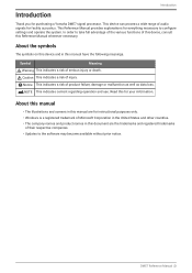
... a Yamaha DME7 signal processor. Notice This indicates a risk of serious injury or death. NOTE This indicates content regarding operation and use. Read this manual have the following meanings. DME7 Reference Manual | 3 Introduction Introduction Thank you for everything necessary to configure settings and operate the system. Symbol Meaning Warning This indicates a risk of product failure, damage or malfunction as well as data...
... a Yamaha DME7 signal processor. Notice This indicates a risk of serious injury or death. NOTE This indicates content regarding operation and use. Read this manual have the following meanings. DME7 Reference Manual | 3 Introduction Introduction Thank you for everything necessary to configure settings and operate the system. Symbol Meaning Warning This indicates a risk of product failure, damage or malfunction as well as data...

DME7 Reference Manual
Page 5
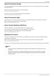
... the setup procedure from connecting the power supply to setting up to 256 × 256 Dante input/output channels*. (* Increasing the number of channels requires additional licenses.) • ProVisionaire Design application software can be used to not only freely program DME7 audio processing but also design an integrated sound system that includes inputs/outputs and amplifiers. • Supports external control Various DCP (wall-recessed control panel) models are supported. It also supports ProVisionaire Control and the tablet software ProVisionaire...
... the setup procedure from connecting the power supply to setting up to 256 × 256 Dante input/output channels*. (* Increasing the number of channels requires additional licenses.) • ProVisionaire Design application software can be used to not only freely program DME7 audio processing but also design an integrated sound system that includes inputs/outputs and amplifiers. • Supports external control Various DCP (wall-recessed control panel) models are supported. It also supports ProVisionaire Control and the tablet software ProVisionaire...
DME7 Reference Manual
Page 6
... Design This Windows application software integrates settings for monitoring local network devices. ProVisionaire Edge must be posted on the version of improving operability, adding functionality, and fixing bugs. Download the software from the following website. Up to monitor the DME7. When a firmware update is available, relevant information will be installed to 8 input/8 output audio signals can be updated for connecting the DME7 to the ProVisionaire Design User Guide (HTML). https://manual.yamaha.com/pa...
... Design This Windows application software integrates settings for monitoring local network devices. ProVisionaire Edge must be posted on the version of improving operability, adding functionality, and fixing bugs. Download the software from the following website. Up to monitor the DME7. When a firmware update is available, relevant information will be installed to 8 input/8 output audio signals can be updated for connecting the DME7 to the ProVisionaire Design User Guide (HTML). https://manual.yamaha.com/pa...
DME7 Reference Manual
Page 8
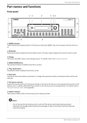
... it again displays the Control Function screen. ③ Display This shows the DME7 status or the settings menus. For details, refer to the "screen flowchart". ④ [MENU/HOME] button This switches between the [Menu] and Home screens. ⑤ (back) button Pressing this device is being accessed. For details, refer to "Using SD memory cards" in green when this button displays the previous screen. ⑥ Main knob Turning the main knob selects...
... it again displays the Control Function screen. ③ Display This shows the DME7 status or the settings menus. For details, refer to the "screen flowchart". ④ [MENU/HOME] button This switches between the [Menu] and Home screens. ⑤ (back) button Pressing this device is being accessed. For details, refer to "Using SD memory cards" in green when this button displays the previous screen. ⑥ Main knob Turning the main knob selects...
DME7 Reference Manual
Page 10
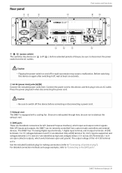
... controllers and external devices. For detailed connection methods and usage examples, refer to "Connecting to "Connecting a Euroblock plug"). DME7 Reference Manual | 9 Connect the power cord to this device before connecting or disconnecting a power cord. ③ Exhaust vent The DME7 is supported, and voltages between 2.5 V and 24 V are open and ground. Only at least six seconds. ② AC IN (power inlet) jacks [A]/[B] Connect the included power cords here. With GPI inputs and outputs, the DME7...
... controllers and external devices. For detailed connection methods and usage examples, refer to "Connecting to "Connecting a Euroblock plug"). DME7 Reference Manual | 9 Connect the power cord to this device before connecting or disconnecting a power cord. ③ Exhaust vent The DME7 is supported, and voltages between 2.5 V and 24 V are open and ground. Only at least six seconds. ② AC IN (power inlet) jacks [A]/[B] Connect the included power cords here. With GPI inputs and outputs, the DME7...
DME7 Reference Manual
Page 11
... external controllers (AMX, Crestron, etc.). 10/100BASE-TX and Auto MDI (no mode switching) functionality is being accessed. Notice • Do not remove the USB flash drive or switch off this device and the media may become damaged, or data on the number of this device functions as the DCP1V4S. Up to the furthest DCP control panel varies depending on this device while data is supported...
... external controllers (AMX, Crestron, etc.). 10/100BASE-TX and Auto MDI (no mode switching) functionality is being accessed. Notice • Do not remove the USB flash drive or switch off this device and the media may become damaged, or data on the number of this device functions as the DCP1V4S. Up to the furthest DCP control panel varies depending on this device while data is supported...

DME7 Reference Manual
Page 13
... ProVisionaire Design User Guide. NOTE • Specifying input/output channels in ProVisionaire Design allows presets from a connected GPI external device to be recalled, parameters to be changed, and signals to be drawn from the two ports is used at [IN] terminal 16, +24 V input is +12 V. Use ProVisionaire Design to GPI controllers. https://manual.yamaha.com/pa/pv/pvd/ Connecting a Euroblock plug Use the included Euroblock plugs to connect to the...
... ProVisionaire Design User Guide. NOTE • Specifying input/output channels in ProVisionaire Design allows presets from a connected GPI external device to be recalled, parameters to be changed, and signals to be drawn from the two ports is used at [IN] terminal 16, +24 V input is +12 V. Use ProVisionaire Design to GPI controllers. https://manual.yamaha.com/pa/pv/pvd/ Connecting a Euroblock plug Use the included Euroblock plugs to connect to the...
DME7 Reference Manual
Page 16
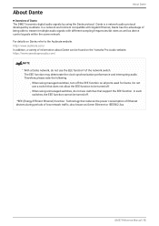
... known as device control signals within the same network. Do not use a switch that does not allow the EEE function to be turned off. ◦ When using managed switches, turn off . *EEE (Energy-Efficient Ethernet) function: Technology that support the EEE function. http://www.audinate.com/ In addition, a variety of information about Dante can be turned off the EEE function on the Yamaha Pro Audio website. https...
... known as device control signals within the same network. Do not use a switch that does not allow the EEE function to be turned off. ◦ When using managed switches, turn off . *EEE (Energy-Efficient Ethernet) function: Technology that support the EEE function. http://www.audinate.com/ In addition, a variety of information about Dante can be turned off the EEE function on the Yamaha Pro Audio website. https...

DME7 Reference Manual
Page 18
... can be connected in the sound. The following is an explanation of network switches can be reduced. Moreover, if a system failure occurs due to split the network. The appropriate latency setting for signals sent and received over a Dante audio network differs depending on the Dante network. As more than one port to the same external switch since this...
... can be connected in the sound. The following is an explanation of network switches can be reduced. Moreover, if a system failure occurs due to split the network. The appropriate latency setting for signals sent and received over a Dante audio network differs depending on the Dante network. As more than one port to the same external switch since this...

DME7 Reference Manual
Page 23
... display only the Input Meter and Output Meter screens. ● Unlocking the panel If the panel is operated while it is locked, the following message will appear on the display. 22 | DME7 Reference Manual A 4-digit authentication number (called a PIN code) can be set for at the top of the Home screen indicates the control function on each alert, refer to prevent accidental parameter changes. Holding down the [MENU/HOME] and (back) buttons...
... display only the Input Meter and Output Meter screens. ● Unlocking the panel If the panel is operated while it is locked, the following message will appear on the display. 22 | DME7 Reference Manual A 4-digit authentication number (called a PIN code) can be set for at the top of the Home screen indicates the control function on each alert, refer to prevent accidental parameter changes. Holding down the [MENU/HOME] and (back) buttons...

DME7 Reference Manual
Page 28
... is always on this device determines the number of licenses activated on ; The number of channels that appear in this meter. Turn the main knob to select [Input Meter] or [Output Meter], and then press the main knob. 2. however, pressing the main knob clears the held peaks for 16 channels at a time. Input Meter/Output Meter Input Meter/Output Meter This indicates the input/output level. Dante input/output is locked, you can display only the Input Meter and Output Meter screens. 1. DME7 Reference Manual | 27
... is always on this device determines the number of licenses activated on ; The number of channels that appear in this meter. Turn the main knob to select [Input Meter] or [Output Meter], and then press the main knob. 2. however, pressing the main knob clears the held peaks for 16 channels at a time. Input Meter/Output Meter Input Meter/Output Meter This indicates the input/output level. Dante input/output is locked, you can display only the Input Meter and Output Meter screens. 1. DME7 Reference Manual | 27

DME7 Reference Manual
Page 33
... specify the length of time after this device has not been operated for unlocking the panel (Enable Unlock PIN) When this is set to [On], PIN code authentication is changed from [10 sec], [30 sec], [1 min], [3 min], [30 min], [1 hour], and [Never]. Select from [Off] to [On], the PIN code input screen appears. 32 | DME7 Reference Manual Select a value between 0% (off...
... specify the length of time after this device has not been operated for unlocking the panel (Enable Unlock PIN) When this is set to [On], PIN code authentication is changed from [10 sec], [30 sec], [1 min], [3 min], [30 min], [1 hour], and [Never]. Select from [Off] to [On], the PIN code input screen appears. 32 | DME7 Reference Manual Select a value between 0% (off...

DME7 Reference Manual
Page 34
... no media has been inserted, "Unsupported Format" if the media is not formatted or mounted, or "Write Protected" if the media is a code used to prevent the device settings from ProVisionaire Design to the ProVisionaire Design User Guide. Turn the main knob to select the item to be saved to save destination, "To USB Memory" will appear instead. DME7 Reference Manual | 33 NOTE •...
... no media has been inserted, "Unsupported Format" if the media is not formatted or mounted, or "Write Protected" if the media is a code used to prevent the device settings from ProVisionaire Design to the ProVisionaire Design User Guide. Turn the main knob to select the item to be saved to save destination, "To USB Memory" will appear instead. DME7 Reference Manual | 33 NOTE •...

DME7 Reference Manual
Page 35
... a Dante network differs depending on the connection method and scale. 34 | DME7 Reference Manual NOTE • Settings in Dante Controller are changed in this device to specify the Dante input/output sampling frequency. Select from [44.1 kHz], [48 kHz], [88.2 kHz], and [96 kHz]. Specifying the encoding (Encoding) This allows you to be used. Specifying the sampling frequency (Sample...
... a Dante network differs depending on the connection method and scale. 34 | DME7 Reference Manual NOTE • Settings in Dante Controller are changed in this device to specify the Dante input/output sampling frequency. Select from [44.1 kHz], [48 kHz], [88.2 kHz], and [96 kHz]. Specifying the encoding (Encoding) This allows you to be used. Specifying the sampling frequency (Sample...

DME7 Reference Manual
Page 42
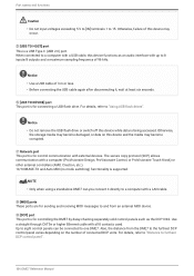
... may stop the power supply to this device. ● Connecting a USB flash drive • Do not remove or install the USB flash drive while data is being written. Notice • When using a USB extension cable, be sure that requires more than 500 mA of current will stop functioning, or the USB flash drive or its data may not work properly with a USB flash drive installed Do not switch off this device...
... may stop the power supply to this device. ● Connecting a USB flash drive • Do not remove or install the USB flash drive while data is being written. Notice • When using a USB extension cable, be sure that requires more than 500 mA of current will stop functioning, or the USB flash drive or its data may not work properly with a USB flash drive installed Do not switch off this device...
DME7 Reference Manual
Page 46
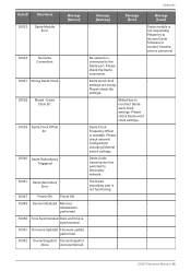
... Please check Dante word clock settings. 30039 Dante Clock Offset - Dante Clock - - DME7 Reference Manual | 45 Connection connected to - Please check the settings. 30038 Muted - Clock Err. settings are wrong. Dante module is unstable. incorrect Dante word clock settings. Frequency Offset is Error not responding. Triiggered transmission has switched to recover Dante firmware or contact Yamaha service personnel. 30034 No Dante - initialization performed. 30050 Time Synchronized Date and time is - - - synchronized. 30051 Firmware Updated Firmware update...
... Please check Dante word clock settings. 30039 Dante Clock Offset - Dante Clock - - DME7 Reference Manual | 45 Connection connected to - Please check the settings. 30038 Muted - Clock Err. settings are wrong. Dante module is unstable. incorrect Dante word clock settings. Frequency Offset is Error not responding. Triiggered transmission has switched to recover Dante firmware or contact Yamaha service personnel. 30034 No Dante - initialization performed. 30050 Time Synchronized Date and time is - - - synchronized. 30051 Firmware Updated Firmware update...
DME7 Reference Manual
Page 50
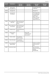
.... Authentication Failed Wrong PIN code/Password was entered. Failed to device. panel is formatted with unsupported file system type. Scene/Snapshot - - Please re-format the storage to a supported format. - - - - - - - - - - - - Message [Fault] DME7 Reference Manual | 49 File Not Found The file cannot be found. Recall Failed 30087 Data Sync Failed - - The storage drive is locked. Appendix Data ID Data Name 30077 30078 30079 Setting Data Corrupted/Lost Storage Full...
.... Authentication Failed Wrong PIN code/Password was entered. Failed to device. panel is formatted with unsupported file system type. Scene/Snapshot - - Please re-format the storage to a supported format. - - - - - - - - - - - - Message [Fault] DME7 Reference Manual | 49 File Not Found The file cannot be found. Recall Failed 30087 Data Sync Failed - - The storage drive is locked. Appendix Data ID Data Name 30077 30078 30079 Setting Data Corrupted/Lost Storage Full...

DME7 Reference Manual
Page 51
... inlet (IEC, V-Lock) x2 Memory device specifications Compatible File format: FAT32, FAT16 formats Supported capacity Maximum media capacity: SDHC: Maximum 32 GB SD: Maximum 2 GB Maximum file FAT16: Maximum 2 GB size FAT32: Maximum 4 GB Controls Front panel Rotary encoder and buttons for GUI control Operation lock feature (Full lock or Lock except volume and mute) Display 224 × 48 pixels, mono color with brightness adjustment Auto display off feature 50 | DME7 Reference Manual
... inlet (IEC, V-Lock) x2 Memory device specifications Compatible File format: FAT32, FAT16 formats Supported capacity Maximum media capacity: SDHC: Maximum 32 GB SD: Maximum 2 GB Maximum file FAT16: Maximum 2 GB size FAT32: Maximum 4 GB Controls Front panel Rotary encoder and buttons for GUI control Operation lock feature (Full lock or Lock except volume and mute) Display 224 × 48 pixels, mono color with brightness adjustment Auto display off feature 50 | DME7 Reference Manual


