
Owner's Manual
Page 7
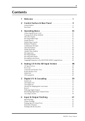
... & Rear Panel 4 Control Surface 4 Rear Panel 29 3 Operating Basics 35 Connecting the Power Cord 35 Turning On & Off the DM2000 35 About the Display 35 Selecting Display Pages 36 Display History 37 Display Page Controls 37 Parameter Windows 37 Confirmation Messages 37 Title Edit Window 38 Using a Keyboard 38 Channel Strip Displays 39 Selecting Layers 42 Selecting Channels 43 Selecting Fader Modes 44 Selecting Encoder Modes 45 Assigning Parameters to the ENCODER MODE Assign Buttons 46 4 Analog I/O & the AD Input...
... & Rear Panel 4 Control Surface 4 Rear Panel 29 3 Operating Basics 35 Connecting the Power Cord 35 Turning On & Off the DM2000 35 About the Display 35 Selecting Display Pages 36 Display History 37 Display Page Controls 37 Parameter Windows 37 Confirmation Messages 37 Title Edit Window 38 Using a Keyboard 38 Channel Strip Displays 39 Selecting Layers 42 Selecting Channels 43 Selecting Fader Modes 44 Selecting Encoder Modes 45 Assigning Parameters to the ENCODER MODE Assign Buttons 46 4 Analog I/O & the AD Input...
Owner's Manual
Page 8
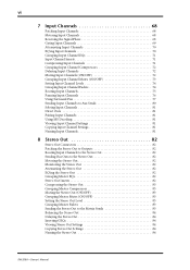
... 71 Input Channel Inserts 71 Compressing Input Channels 71 Grouping Input Channel Compressors 72 Delaying Input Channels 72 Muting Input Channels (ON/OFF 72 Grouping Input Channel Mutes (ON/OFF 73 Setting Input Channel Levels 74 Grouping Input Channel Faders 74 Routing Input Channels 75 Panning Input Channels 76 Using Surround Pan 77 Sending Input Channels to Aux Sends 80 Soloing Input Channels 81 Direct Outs 81 Pairing Input Channels 81 Using MS Decoding 81 Viewing Input Channel Settings 81 Copying Input Channel Settings 81 Naming Input Channels 81 8 Stereo Out 82 Stereo...
... 71 Input Channel Inserts 71 Compressing Input Channels 71 Grouping Input Channel Compressors 72 Delaying Input Channels 72 Muting Input Channels (ON/OFF 72 Grouping Input Channel Mutes (ON/OFF 73 Setting Input Channel Levels 74 Grouping Input Channel Faders 74 Routing Input Channels 75 Panning Input Channels 76 Using Surround Pan 77 Sending Input Channels to Aux Sends 80 Soloing Input Channels 81 Direct Outs 81 Pairing Input Channels 81 Using MS Decoding 81 Viewing Input Channel Settings 81 Copying Input Channel Settings 81 Naming Input Channels 81 8 Stereo Out 82 Stereo...
Owner's Manual
Page 13
... Configuring Master Track Arming 226 Configuring Track Arming Groups 227 GPI (General Purpose Interface 228 Controlling AD824 A/D Converters 229 21 Other Functions 230 Using the User Defined Keys 230 Saving DM2000 Data to SmartMedia 231 Setting Preferences 234 Using the Oscillator 238 Checking the Battery 238 Initializing the DM2000 239 Appendix A: Parameter Lists 240 USER DEFINED KEYS 240 USER DEFINED KEYS Initial Assignments 242 Input Patch Parameters 242 Initial Input Patch Settings 246 Output Patch...
... Configuring Master Track Arming 226 Configuring Track Arming Groups 227 GPI (General Purpose Interface 228 Controlling AD824 A/D Converters 229 21 Other Functions 230 Using the User Defined Keys 230 Saving DM2000 Data to SmartMedia 231 Setting Preferences 234 Using the Oscillator 238 Checking the Battery 238 Initializing the DM2000 239 Appendix A: Parameter Lists 240 USER DEFINED KEYS 240 USER DEFINED KEYS Initial Assignments 242 Input Patch Parameters 242 Initial Input Patch Settings 246 Output Patch...
Owner's Manual
Page 15
..., 1 Coaxial 2-track digital input • 2 AES/EBU, 1 Coaxial 2-track digital output • 2 analog 2-track inputs • XLR and phone jack stereo outputs • Large and small control room outputs • Dedicated studio monitor outputs • AES/EBU and Coaxial I/O sampling rate converters for connecting 44.1/48 kHz legacy digital audio equipment • Double channel digital I /O Architecture • 24 analog mic/line inputs on balanced XLRs and phone jacks (plus 48 V phantom) • 24 analog inserts on control of...
..., 1 Coaxial 2-track digital input • 2 AES/EBU, 1 Coaxial 2-track digital output • 2 analog 2-track inputs • XLR and phone jack stereo outputs • Large and small control room outputs • Dedicated studio monitor outputs • AES/EBU and Coaxial I/O sampling rate converters for connecting 44.1/48 kHz legacy digital audio equipment • Double channel digital I /O Architecture • 24 analog mic/line inputs on balanced XLRs and phone jacks (plus 48 V phantom) • 24 analog inserts on control of...
Owner's Manual
Page 20
.... 6 Chapter 2-Control Surface & Rear Panel D SOLO buttons These buttons are used to select Matrix Sends when sending Bus Out, Aux Send, and Stereo Out signals to Matrix Sends. They also display routing settings, and the on the currently selected Layer. Their exact operation depends on page 39 for more information. The [SOLO] button indicators of the EQ, Insert, Delay, Comp, and Gate functions. See "Soloing Channels" on light up . Faders can be grouped for use with...
.... 6 Chapter 2-Control Surface & Rear Panel D SOLO buttons These buttons are used to select Matrix Sends when sending Bus Out, Aux Send, and Stereo Out signals to Matrix Sends. They also display routing settings, and the on the currently selected Layer. Their exact operation depends on page 39 for more information. The [SOLO] button indicators of the EQ, Insert, Delay, Comp, and Gate functions. See "Soloing Channels" on light up . Faders can be grouped for use with...
Owner's Manual
Page 47
...] button or [2TR D2] button. Unsynchronized digital audio signals can be cascaded with an 02R Digital Recording Console. Signals connected here can be patched Input Channels or Insert Ins. In addition, these outputs: Stereo Out, Bus Outs, Aux Sends, Matrix Sends, Direct Outs, Insert Outs, and Control Room. Unsynchronized digital audio signals can be converted by pressing the CONTROL ROOM [2TR D3] button. See "GPI (General Purpose Interface)" on page 52 for more information. DM2000-Owner's Manual Rear Panel 33 K 2TR OUT DIGITAL...
...] button or [2TR D2] button. Unsynchronized digital audio signals can be cascaded with an 02R Digital Recording Console. Signals connected here can be patched Input Channels or Insert Ins. In addition, these outputs: Stereo Out, Bus Outs, Aux Sends, Matrix Sends, Direct Outs, Insert Outs, and Control Room. Unsynchronized digital audio signals can be converted by pressing the CONTROL ROOM [2TR D3] button. See "GPI (General Purpose Interface)" on page 52 for more information. DM2000-Owner's Manual Rear Panel 33 K 2TR OUT DIGITAL...
Owner's Manual
Page 64
... digital audio connections, including AES/EBU, ADAT, and Tascam formats. The DM2000 can be received correctly and audible noise, glitches, or clicks may not be connected to the WORD CLOCK IN connector, and terminated by using only analog inputs and outputs, no special wordclock settings are correctly locked to the wordclock master. When shutting down the system, turn off the slaves first, and then the master. External...
... digital audio connections, including AES/EBU, ADAT, and Tascam formats. The DM2000 can be received correctly and audible noise, glitches, or clicks may not be connected to the WORD CLOCK IN connector, and terminated by using only analog inputs and outputs, no special wordclock settings are correctly locked to the wordclock master. When shutting down the system, turn off the slaves first, and then the master. External...
Owner's Manual
Page 67
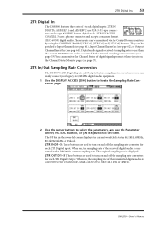
... Digital Ins 53 2TR Digital Ins The DM2000 features three sets of 2-track digital inputs: 2TR IN DIGITAL AES/EBU 1 and AES/EBU 2 use the Parameter wheel, INC/DEC buttons, or [ENTER] button to set to turn on the Channel Status Monitor page (see page 64). Digital audio signals received at these inputs on and off the sampling rate converters for each 2TR Digital Output. They can be converted by using the CONTROL...
... Digital Ins 53 2TR Digital Ins The DM2000 features three sets of 2-track digital inputs: 2TR IN DIGITAL AES/EBU 1 and AES/EBU 2 use the Parameter wheel, INC/DEC buttons, or [ENTER] button to set to turn on the Channel Status Monitor page (see page 64). Digital audio signals received at these inputs on and off the sampling rate converters for each 2TR Digital Output. They can be converted by using the CONTROL...
Owner's Manual
Page 140
... Input Channel are the Matrix Send Level controls for more information. The Direct Out output patch can be turned on and off by pressing [ENTER]. See "Aux Sends" on page 75 for the currently selected Bus Out. Bus Outs This is selected. While a rotary control is in . GROUP: These buttons indicate which Fader, Mute, EQ, or Comp group, if any , the currently selected Input Channel is displayed numerically below the fader. See "Muting Bus...
... Input Channel are the Matrix Send Level controls for more information. The Direct Out output patch can be turned on and off by pressing [ENTER]. See "Aux Sends" on page 75 for the currently selected Bus Out. Bus Outs This is selected. While a rotary control is in . GROUP: These buttons indicate which Fader, Mute, EQ, or Comp group, if any , the currently selected Input Channel is displayed numerically below the fader. See "Muting Bus...
Owner's Manual
Page 148
... user memories. The meters indicate Bus Out signal levels. MUTE/SOLO: These parameters are used to the standard Ls and Rs speakers, the DM2000 supports Ls2 and Rs2 speakers, with the [ASSIGN 1] and [ASSIGN 2] buttons. A Surround Channel is on when its speaker icon is on each ASSIGN button, in this section are mixed. The number of the Slots specified on the currently selected Surround mode. SETTING: These buttons are pressed. The [ASSIGN 1] and [ASSIGN 2] buttons...
... user memories. The meters indicate Bus Out signal levels. MUTE/SOLO: These parameters are used to the standard Ls and Rs speakers, the DM2000 supports Ls2 and Rs2 speakers, with the [ASSIGN 1] and [ASSIGN 2] buttons. A Surround Channel is on when its speaker icon is on each ASSIGN button, in this section are mixed. The number of the Slots specified on the currently selected Surround mode. SETTING: These buttons are pressed. The [ASSIGN 1] and [ASSIGN 2] buttons...
Owner's Manual
Page 181
... operations. They can be set , cannot be edited while recording is in and out points is recalled, when an of the Automix. Parameter button FADER ON PAN SURR AUX AUX ON EQ Description Channel faders (Inputs Channels, Bus Out masters, Aux Send masters, Matrix Send masters, the Stereo Out, and User Defined Layer faders) Channel Mutes (ON/OFF), User Defined Layer [ON] buttons Input Channel Pan, User Defined Layer Encoders Input Channel Surround pan, LFE level...
... operations. They can be set , cannot be edited while recording is in and out points is recalled, when an of the Automix. Parameter button FADER ON PAN SURR AUX AUX ON EQ Description Channel faders (Inputs Channels, Bus Out masters, Aux Send masters, Matrix Send masters, the Stereo Out, and User Defined Layer faders) Channel Mutes (ON/OFF), User Defined Layer [ON] buttons Input Channel Pan, User Defined Layer Encoders Input Channel Surround pan, LFE level...
Owner's Manual
Page 202
... DISPLAY ACCESS [REMOTE] button to locate the Remote pages, and assign Pro Tools to a USB port on your PC, or by connecting the TO HOST USB port to a Remote Layer. DM2000-Owner's Manual Once your Mac, there's no need to install it 's included on the DM2000 CD-ROM. If you need to select an Input Channel Layer or the Master Layer. If you must also install the Yamaha USB MIDI driver...
... DISPLAY ACCESS [REMOTE] button to locate the Remote pages, and assign Pro Tools to a USB port on your PC, or by connecting the TO HOST USB port to a Remote Layer. DM2000-Owner's Manual Once your Mac, there's no need to install it 's included on the DM2000 CD-ROM. If you need to select an Input Channel Layer or the Master Layer. If you must also install the Yamaha USB MIDI driver...
Owner's Manual
Page 233
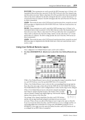
... the data. When a Scene is recalled, if the Remote Layer's target is operated. While a User Defined Remote Layer is adjusted. Only one Learn function can be used to be changed. LEARN: This works the same as when the Scene was stored, the faders, Encoders, and [ON] buttons are used at a time. When a User Defined Remote Layer is selected, the channel strip displays show Remote channel...
... the data. When a Scene is recalled, if the Remote Layer's target is operated. While a User Defined Remote Layer is adjusted. Only one Learn function can be used to be changed. LEARN: This works the same as when the Scene was stored, the faders, Encoders, and [ON] buttons are used at a time. When a User Defined Remote Layer is selected, the channel strip displays show Remote channel...
Owner's Manual
Page 242
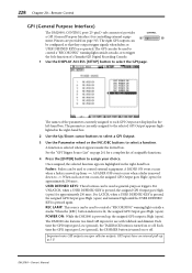
... outputs are operated. A function is moved up to assign your choice. USER DEFINED KEYS: These buttons can be configured so that they output trigger signals when faders or USER DEFINED KEYS are open ). For UNLATCH, when a USER DEFINED KEY is turned on or off . When such an event occurs, the assigned GPI Output goes High (open ) for a complete list of a Yamaha 02R Digital Recording Console. 1 Use the DISPLAY ACCESS [SETUP] button to control external equipment. The DM2000...
... outputs are operated. A function is moved up to assign your choice. USER DEFINED KEYS: These buttons can be configured so that they output trigger signals when faders or USER DEFINED KEYS are open ). For UNLATCH, when a USER DEFINED KEY is turned on or off . When such an event occurs, the assigned GPI Output goes High (open ) for a complete list of a Yamaha 02R Digital Recording Console. 1 Use the DISPLAY ACCESS [SETUP] button to control external equipment. The DM2000...
Owner's Manual
Page 333
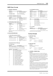
.../tx function DM2000-specific parameter change DM2000-specific parameter request General purpose digital mixer parameter change General purpose digital mixer parameter request The following data types of parameter change are defined in the CONTROL CHANGE ASSIGN PARAMETER LIST. CHANNEL MESSAGE Command 8n NOTE OFF 9n NOTE ON Bn CONTROL CHANGE Cn PROGRAM CHANGE rx/tx rx rx rx/tx rx/tx function Control the internal effects Control the internal effects Control parameters Switch scene memories 2. EXCLUSIVE MESSAGE 4.1 Real Time System...
.../tx function DM2000-specific parameter change DM2000-specific parameter request General purpose digital mixer parameter change General purpose digital mixer parameter request The following data types of parameter change are defined in the CONTROL CHANGE ASSIGN PARAMETER LIST. CHANNEL MESSAGE Command 8n NOTE OFF 9n NOTE ON Bn CONTROL CHANGE Cn PROGRAM CHANGE rx/tx rx rx rx/tx rx/tx function Control the internal effects Control the internal effects Control parameters Switch scene memories 2. EXCLUSIVE MESSAGE 4.1 Real Time System...
Owner's Manual
Page 351
... bus to stereo library 143 channel library 140 compressors 113 copying 129 delay 117 EQ 107 grouping faders 122 grouping mutes 123 inserts 111 level setting 86 metering 104 muting 86 naming 130 pairing 120 patching GEQs 66 patching to 2TR digital outputs 65 patching to input channels 61 patching to omni outs 64 patching to slot outputs 63 routing to 75 routing to 2TR digital outputs 65 setup 133 CONTROL ROOM button 26 CONTROL ROOM LEVEL control...
... bus to stereo library 143 channel library 140 compressors 113 copying 129 delay 117 EQ 107 grouping faders 122 grouping mutes 123 inserts 111 level setting 86 metering 104 muting 86 naming 130 pairing 120 patching GEQs 66 patching to 2TR digital outputs 65 patching to input channels 61 patching to omni outs 64 patching to slot outputs 63 routing to 75 routing to 2TR digital outputs 65 setup 133 CONTROL ROOM button 26 CONTROL ROOM LEVEL control...
Owner's Manual
Page 354
... preference 235 METER port 33 Meter, time signature map 172 Metering effects 104 input channels 103 metering position 103 output channels 104 stereo out 105 METERING POSITION page 103 MIDI bulk dump 187 control change messages 186 data format 319 features 3 I /O cards 55 INTERNAL EFFECTS button 9 Internal effects, plug-ins & GEQs chapter 148 Internal timecode source 171 Internet, yamaha web site iv Inverse gang mode aux send pan 94 input channel pan 77 Inverting input channel phase 68 J Joystick about 16 panning input channels 76 reverb 5.1 effect 286...
... preference 235 METER port 33 Meter, time signature map 172 Metering effects 104 input channels 103 metering position 103 output channels 104 stereo out 105 METERING POSITION page 103 MIDI bulk dump 187 control change messages 186 data format 319 features 3 I /O cards 55 INTERNAL EFFECTS button 9 Internal effects, plug-ins & GEQs chapter 148 Internal timecode source 171 Internet, yamaha web site iv Inverse gang mode aux send pan 94 input channel pan 77 Inverting input channel phase 68 J Joystick about 16 panning input channels 76 reverb 5.1 effect 286...
Owner's Manual
Page 356
... input channel phase 68 DM2000-Owner's Manual See Pre/post Post-roll, machine control 224 Power cord 35 POWER switch 34 Powering up the DM2000 35 PRE button 22 Pre/post aux sends 88 matrix sends 97 metering 103 solo 119 PREFERENCES1 page 234 PREFERENCES2 page 236 PREFERENCES3 page 237 Pre-roll, machine control 224 Presets compressors 113 effects 148 EQ 107 gates 69 Pro tools arming parameters for automation 216 assigning inputs to channels 203 assigning inserts/plug-ins 209 assigning outputs to channels...
... input channel phase 68 DM2000-Owner's Manual See Pre/post Post-roll, machine control 224 Power cord 35 POWER switch 34 Powering up the DM2000 35 PRE button 22 Pre/post aux sends 88 matrix sends 97 metering 103 solo 119 PREFERENCES1 page 234 PREFERENCES2 page 236 PREFERENCES3 page 237 Pre-roll, machine control 224 Presets compressors 113 effects 148 EQ 107 gates 69 Pro tools arming parameters for automation 216 assigning inputs to channels 203 assigning inserts/plug-ins 209 assigning outputs to channels...
Studio Manager Installation Guide
Page 16
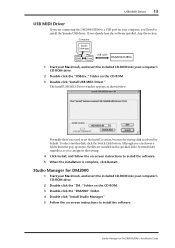
... install the Yamaha USB driver. Studio Manager for DM2000/02R96-Installation Guide Computer Studio Manager OMS USB cable Driver DM2000/02R96 1 Start your Macintosh, and insert the included CD-ROM into your computer's CD-ROM drive. 2 Double-click the "SM_" folder on the CD-ROM. 3 Double-click the "DM2000" folder. 4 Double-click "Install Studio Manager." 5 Follow the on-screen instructions to install the software. To select another disk, click the Switch Disk button. USB MIDI Driver 13 USB MIDI Driver...
... install the Yamaha USB driver. Studio Manager for DM2000/02R96-Installation Guide Computer Studio Manager OMS USB cable Driver DM2000/02R96 1 Start your Macintosh, and insert the included CD-ROM into your computer's CD-ROM drive. 2 Double-click the "SM_" folder on the CD-ROM. 3 Double-click the "DM2000" folder. 4 Double-click "Install Studio Manager." 5 Follow the on-screen instructions to install the software. To select another disk, click the Switch Disk button. USB MIDI Driver 13 USB MIDI Driver...
Studio Manager Owner's Manual
Page 8
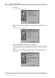
The window appears as shown below . Note: You may be located. Specify the USBdrv_ folder of the CD-ROM (such as shown. 5 Chapter 1-Getting Started 5 Click Next. The window appears, as shown below. 6 Select "Search for the best driver for your Windows CD-ROM so that the driver can be asked to insert your device. (Recommended)." When the driver is found, "YAMAHA USB MIDI Driver" is displayed in the window as shown below . 7 Select "CD-ROM drive" only, as D:\USBdrv_\) and continue the installation. Click Next. Click Next. Studio Manager-Owner's Manual
The window appears as shown below . Note: You may be located. Specify the USBdrv_ folder of the CD-ROM (such as shown. 5 Chapter 1-Getting Started 5 Click Next. The window appears, as shown below. 6 Select "Search for the best driver for your Windows CD-ROM so that the driver can be asked to insert your device. (Recommended)." When the driver is found, "YAMAHA USB MIDI Driver" is displayed in the window as shown below . 7 Select "CD-ROM drive" only, as D:\USBdrv_\) and continue the installation. Click Next. Click Next. Studio Manager-Owner's Manual


