

Dm2000 Update V1.1
Page 3
... turned on or off (i.e., [CONTROL ROOM], [STEREO], [AUX 11], and [AUX 12]), the Solo signal is output by the STUDIO MONITOR OUT when channels are assigned to the USER DEFINED KEYS on the Preferences 1 page, which is selected by using the USER DEFINED KEYS [DISPLAY] button. Recall +1 162 Surr...to Studio Out preference on the USER DEFINED KEY ASSIGN page, which can be selected by using the DISPLAY ACCESS [SETUP] button, soloed channels can now be controlled remotely via the CONTROL Port The Control Room and Surround Monitor Dimmers, and the Talkback function can now be assigned to...
... turned on or off (i.e., [CONTROL ROOM], [STEREO], [AUX 11], and [AUX 12]), the Solo signal is output by the STUDIO MONITOR OUT when channels are assigned to the USER DEFINED KEYS on the Preferences 1 page, which is selected by using the USER DEFINED KEYS [DISPLAY] button. Recall +1 162 Surr...to Studio Out preference on the USER DEFINED KEY ASSIGN page, which can be selected by using the DISPLAY ACCESS [SETUP] button, soloed channels can now be controlled remotely via the CONTROL Port The Control Room and Surround Monitor Dimmers, and the Talkback function can now be assigned to...
Owner's Manual
Page 6
... Production Console. Display pages can be selected. Installing the DM2000 The DM2000 should be placed on a strong and stable surface, somewhere that appear on all channels. Functions such as EQ and Delay are explained once in which starts on the Yamaha Professional Audio Web site at: . Before diving in the procedures. References to locate...
... Production Console. Display pages can be selected. Installing the DM2000 The DM2000 should be placed on a strong and stable surface, somewhere that appear on all channels. Functions such as EQ and Delay are explained once in which starts on the Yamaha Professional Audio Web site at: . Before diving in the procedures. References to locate...
Owner's Manual
Page 7
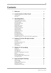
... Surface & Rear Panel 4 Control Surface 4 Rear Panel 29 3 Operating Basics 35 Connecting the Power Cord 35 Turning On & Off the DM2000 35 About the Display 35 Selecting Display Pages 36 Display History 37 Display Page Controls 37 Parameter Windows 37 Confirmation Messages 37 Title Edit Window ...Digital Outs 52 2TR Digital Ins 53 2TR In/Out Sampling Rate Conversion 53 Slot I/O 54 Dithering Digital Outputs 57 Monitoring Digital Input Channel Status 57 Cascading Consoles 58 6 Input & Output Patching 61 Input Patching 61 Output Patching 63 Naming Input & Output Ports 66 Patch...
... Surface & Rear Panel 4 Control Surface 4 Rear Panel 29 3 Operating Basics 35 Connecting the Power Cord 35 Turning On & Off the DM2000 35 About the Display 35 Selecting Display Pages 36 Display History 37 Display Page Controls 37 Parameter Windows 37 Confirmation Messages 37 Title Edit Window ...Digital Outs 52 2TR Digital Ins 53 2TR In/Out Sampling Rate Conversion 53 Slot I/O 54 Dithering Digital Outputs 57 Monitoring Digital Input Channel Status 57 Cascading Consoles 58 6 Input & Output Patching 61 Input Patching 61 Output Patching 63 Naming Input & Output Ports 66 Patch...
Owner's Manual
Page 8
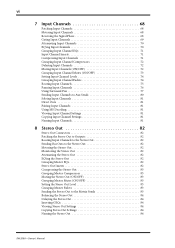
vi 7 Input Channels 68 Patching Input Channels 68 Metering Input Channels 68 Reversing the Signal Phase 68 Gating Input Channels 69 Attenuating Input Channels 70 EQ'ing Input Channels 70 Grouping Input Channel EQs 71 Input Channel Inserts 71 Compressing Input Channels 71 Grouping Input Channel Compressors 72 Delaying Input Channels 72 Muting Input Channels (ON/OFF 72 Grouping Input Channel Mutes (ON/OFF... Out 84 Delaying the Stereo Out 84 Inserting GEQs 84 Viewing Stereo Out Settings 84 Copying Stereo Out Settings 84 Naming the Stereo Out 84 DM2000-Owner's Manual
vi 7 Input Channels 68 Patching Input Channels 68 Metering Input Channels 68 Reversing the Signal Phase 68 Gating Input Channels 69 Attenuating Input Channels 70 EQ'ing Input Channels 70 Grouping Input Channel EQs 71 Input Channel Inserts 71 Compressing Input Channels 71 Grouping Input Channel Compressors 72 Delaying Input Channels 72 Muting Input Channels (ON/OFF 72 Grouping Input Channel Mutes (ON/OFF... Out 84 Delaying the Stereo Out 84 Inserting GEQs 84 Viewing Stereo Out Settings 84 Copying Stereo Out Settings 84 Naming the Stereo Out 84 DM2000-Owner's Manual

Owner's Manual
Page 9
vii 9 Bus Outs 85 Patching Bus Outs to Outputs 85 Routing Input Channels to Bus Outs 85 Metering Bus Outs 85 Monitoring Bus Outs 85 Attenuating Bus Outs 85 EQ'ing Bus Outs 85 Grouping Master EQs 85 ... Soloing Aux Sends 96 Pairing Aux Sends 96 Viewing Aux Send Master Settings 96 Copying Aux Send Master Settings 96 Naming Aux Send Masters 96 DM2000-Owner's Manual
vii 9 Bus Outs 85 Patching Bus Outs to Outputs 85 Routing Input Channels to Bus Outs 85 Metering Bus Outs 85 Monitoring Bus Outs 85 Attenuating Bus Outs 85 EQ'ing Bus Outs 85 Grouping Master EQs 85 ... Soloing Aux Sends 96 Pairing Aux Sends 96 Viewing Aux Send Master Settings 96 Copying Aux Send Master Settings 96 Naming Aux Send Masters 96 DM2000-Owner's Manual

Owner's Manual
Page 10
... Channel Compressors 116 Delaying Channel Signals 117 Soloing Channels 118 Pairing Channels 120 Grouping Output Channel Faders 122 Grouping Output Channel Mutes (ON/OFF 123 Viewing Channel Parameter Settings 124 Viewing Channel Fader Settings 125 Copying Channel Settings 129 Naming Channels 130 13 Monitoring & Talkback 132 Control Room Monitoring 132 Studio Monitoring 133 Surround Monitoring 134 Using Talkback & Slate 138 DM2000...
... Channel Compressors 116 Delaying Channel Signals 117 Soloing Channels 118 Pairing Channels 120 Grouping Output Channel Faders 122 Grouping Output Channel Mutes (ON/OFF 123 Viewing Channel Parameter Settings 124 Viewing Channel Fader Settings 125 Copying Channel Settings 129 Naming Channels 130 13 Monitoring & Talkback 132 Control Room Monitoring 132 Studio Monitoring 133 Surround Monitoring 134 Using Talkback & Slate 138 DM2000...

Owner's Manual
Page 11
ix 14 Libraries 139 About the Libraries 139 General Library Operation 139 Channel Library 140 Input Patch Library 141 Output Patch Library 141 GEQ Library 142 Effects Library 142 ...Sorting Scenes 163 17 Automix 164 About Automix 164 What's Recorded in an Automix 164 Automix Main Page 165 AUTOMIX Section 168 Channel Strip [AUTO] Buttons 169 Automix Memory Page 169 Fader Edit Pages 170 Selecting the Timecode Source & Frame Rate 171 Creating a...Recording 174 Punching In & Out Individual Parameters 175 Playing Back an Automix 176 Editing Events Offline 177 DM2000-Owner's Manual
ix 14 Libraries 139 About the Libraries 139 General Library Operation 139 Channel Library 140 Input Patch Library 141 Output Patch Library 141 GEQ Library 142 Effects Library 142 ...Sorting Scenes 163 17 Automix 164 About Automix 164 What's Recorded in an Automix 164 Automix Main Page 165 AUTOMIX Section 168 Channel Strip [AUTO] Buttons 169 Automix Memory Page 169 Fader Edit Pages 170 Selecting the Timecode Source & Frame Rate 171 Creating a...Recording 174 Punching In & Out Individual Parameters 175 Playing Back an Automix 176 Editing Events Offline 177 DM2000-Owner's Manual

Owner's Manual
Page 12
x 18 MIDI 182 MIDI & the DM2000 182 MIDI I/O 182 MIDI Port Setup 183 MIDI Channel Setup 184 Assigning Scenes to Program Changes 185 Assigning Parameters to Control Changes 186 Controlling Parameters by Using Parameter ... Computers 188 Configuring the DM2000 188 Configuring Pro Tools 189 Control Surface Operation with the Pro Tools Remote Layer 190 Scrolling Windows 203 Selecting Channels 203 Assigning Inputs to Channels 203 Assigning Outputs to Channels 204 Setting Channel Levels 204 Muting Channels 205 Panning Channels 205 Soloing Channels 205 Assigning Send Destinations ...
x 18 MIDI 182 MIDI & the DM2000 182 MIDI I/O 182 MIDI Port Setup 183 MIDI Channel Setup 184 Assigning Scenes to Program Changes 185 Assigning Parameters to Control Changes 186 Controlling Parameters by Using Parameter ... Computers 188 Configuring the DM2000 188 Configuring Pro Tools 189 Control Surface Operation with the Pro Tools Remote Layer 190 Scrolling Windows 203 Selecting Channels 203 Assigning Inputs to Channels 203 Assigning Outputs to Channels 204 Setting Channel Levels 204 Muting Channels 205 Panning Channels 205 Soloing Channels 205 Assigning Send Destinations ...
Owner's Manual
Page 13
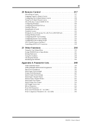
... Checking the Battery 238 Initializing the DM2000 239 Appendix A: Parameter Lists 240 USER DEFINED KEYS 240 USER DEFINED KEYS Initial Assignments 242 Input Patch Parameters 242 Initial Input Patch Settings 246 Output Patch Parameters 247 Initial Output Patch Settings 255 Initial Input Channel Names 256 Initial Output Channel Names 257 Initial Input Port...
... Checking the Battery 238 Initializing the DM2000 239 Appendix A: Parameter Lists 240 USER DEFINED KEYS 240 USER DEFINED KEYS Initial Assignments 242 Input Patch Parameters 242 Initial Input Patch Settings 246 Output Patch Parameters 247 Initial Output Patch Settings 255 Initial Input Channel Names 256 Initial Output Channel Names 257 Initial Input Port...
Owner's Manual
Page 15
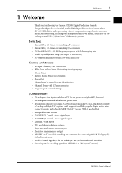
... • 108 dB typical dynamic range (AD Input to Stereo Out) • 32-bit internal signal processing (58-bit accumulator) Channel Architecture • 96 Input Channels, with Direct Outs • 8 Bus Outs, with to Stereo Out routing for subgrouping • 12 Aux Sends • 4 ...I/O sampling rate converters for connecting 44.1/48 kHz legacy digital audio equipment • Double channel digital I/O for use with legacy 44.1/48 kHz multitrack recorders • Cascade ports for choosing the Yamaha DM2000 Digital Production Console. Welcome 1 1 Welcome Thank you for cascading up to four...
... • 108 dB typical dynamic range (AD Input to Stereo Out) • 32-bit internal signal processing (58-bit accumulator) Channel Architecture • 96 Input Channels, with Direct Outs • 8 Bus Outs, with to Stereo Out routing for subgrouping • 12 Aux Sends • 4 ...I/O sampling rate converters for connecting 44.1/48 kHz legacy digital audio equipment • Double channel digital I/O for use with legacy 44.1/48 kHz multitrack recorders • Cascade ports for choosing the Yamaha DM2000 Digital Production Console. Welcome 1 1 Welcome Thank you for cascading up to four...

Owner's Manual
Page 16
...to the Input Channels, Insert Ins... Input and Output Channels • EQ library with 40 presets...Channels • Horizontal pairing of Bus Outs, Aux Sends, and Surround Pan • 8 Input Channel, 4 Output Channel Fader groups • 8 Input Channel, 4 Output Channel Mute groups • 4 Input Channel, 4 Output Channel EQ groups • 4 Input Channel, 4 Output Channel...Channels • Gate library with 4 presets, 124 user memories • Compressors on all Input Channels and Out Channels...library recalls • Punch in/out entire channels with dedicated [AUTO] buttons, or individual ...
...to the Input Channels, Insert Ins... Input and Output Channels • EQ library with 40 presets...Channels • Horizontal pairing of Bus Outs, Aux Sends, and Surround Pan • 8 Input Channel, 4 Output Channel Fader groups • 8 Input Channel, 4 Output Channel Mute groups • 4 Input Channel, 4 Output Channel EQ groups • 4 Input Channel, 4 Output Channel...Channels • Gate library with 4 presets, 124 user memories • Compressors on all Input Channels and Out Channels...library recalls • Punch in/out entire channels with dedicated [AUTO] buttons, or individual ...

Owner's Manual
Page 17
...8226; Remote control of repetitive tasks • Display History buttons for quick access to 12 Yamaha AD824 A/D Converters MIDI • Standard MIDI ports, USB TO HOST port, SERIAL TO ...• Scene recall, mix parameter control, Bulk Dump, MTC and MIDI Clock for quick title entry DM2000-Owner's Manual Welcome 3 Surround Sound • 3-1 and 5.1 Surround modes • Joystick control &#...for controlling MIDI equipment, with Learn function • Comprehensive machine control via the SELECTED CHANNEL section • 2-digit Scene memory display • 4 EQ displays for frequency, gain...
...8226; Remote control of repetitive tasks • Display History buttons for quick access to 12 Yamaha AD824 A/D Converters MIDI • Standard MIDI ports, USB TO HOST port, SERIAL TO ...• Scene recall, mix parameter control, Bulk Dump, MTC and MIDI Clock for quick title entry DM2000-Owner's Manual Welcome 3 Surround Sound • 3-1 and 5.1 Surround modes • Joystick control &#...for controlling MIDI equipment, with Learn function • Comprehensive machine control via the SELECTED CHANNEL section • 2-digit Scene memory display • 4 EQ displays for frequency, gain...

Owner's Manual
Page 18
4 Chapter 2-Control Surface & Rear Panel 2 Control Surface & Rear Panel Control Surface DM2000-Owner's Manual AD Input Section (p. 5) DISPLAY ACCESS (p. 8) Display Section (p. 11) SELECTED CHANNEL Section (p. 12) Monitor, Phones & Talkback Section (p. 25) SmartMedia CARD Slot (p. 6) MATRIX SELECT (p. 6)... 4 INPUT OUTPUT SEND ASSIGN INSERT 5 6 7 8 F1 F2 F3 F4 1 2 3 4 ROUTING DISPLAY 1 2 3 4 5 6 SELECTED CHANNEL PHASE / INSERT DELAY DISPLAY INSERT ON AUX / MATRIX SEND DISPLAY ON FB MIX TIME DISPLAY LEVEL LEVEL LEVEL LEVEL 7 8 FOLLOW PAN STEREO DIRECT ...
4 Chapter 2-Control Surface & Rear Panel 2 Control Surface & Rear Panel Control Surface DM2000-Owner's Manual AD Input Section (p. 5) DISPLAY ACCESS (p. 8) Display Section (p. 11) SELECTED CHANNEL Section (p. 12) Monitor, Phones & Talkback Section (p. 25) SmartMedia CARD Slot (p. 6) MATRIX SELECT (p. 6)... 4 INPUT OUTPUT SEND ASSIGN INSERT 5 6 7 8 F1 F2 F3 F4 1 2 3 4 ROUTING DISPLAY 1 2 3 4 5 6 SELECTED CHANNEL PHASE / INSERT DELAY DISPLAY INSERT ON AUX / MATRIX SEND DISPLAY ON FB MIX TIME DISPLAY LEVEL LEVEL LEVEL LEVEL 7 8 FOLLOW PAN STEREO DIRECT ...

Owner's Manual
Page 19
...modes, with the 0 10 SELECTED CHANNEL section. See "Selecting Encoder Modes" on page 45 for editing with over 40 5 parameters to the Encoders in Record-Ready mode, red while recording, and green during Automix recording. DM2000-Owner's Manual D PEAK indicators These... indicators light up orange in and out during playback. E SIGNAL indicators These indicators light up . 10 20 See "Selecting Channels" on page 42 for more information. 2 AUTO A...
...modes, with the 0 10 SELECTED CHANNEL section. See "Selecting Encoder Modes" on page 45 for editing with over 40 5 parameters to the Encoders in Record-Ready mode, red while recording, and green during Automix recording. DM2000-Owner's Manual D PEAK indicators These... indicators light up orange in and out during playback. E SIGNAL indicators These indicators light up . 10 20 See "Selecting Channels" on page 42 for more information. 2 AUTO A...
Owner's Manual
Page 20
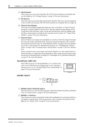
... D SOLO buttons These buttons are used to SmartMedia" on page 231 for more information. See "Saving DM2000 Data to solo Channels. The [SOLO] button indicators of channels that are used to select Matrix Sends when sending Bus Out, Aux Send, and Stereo Out signals to...These buttons are soloed light up . DM2000-Owner's Manual See "Grouping Input Channel Faders" on page 74 and "Grouping Output Channel Faders" on . Faders can also be used to mute Input and Output Channels. E ON buttons These buttons are used to store DM2000 data, including Setups, Scenes, Automixes...
... D SOLO buttons These buttons are used to SmartMedia" on page 231 for more information. See "Saving DM2000 Data to solo Channels. The [SOLO] button indicators of channels that are used to select Matrix Sends when sending Bus Out, Aux Send, and Stereo Out signals to...These buttons are soloed light up . DM2000-Owner's Manual See "Grouping Input Channel Faders" on page 74 and "Grouping Output Channel Faders" on . Faders can also be used to mute Input and Output Channels. E ON buttons These buttons are used to store DM2000 data, including Setups, Scenes, Automixes...

Owner's Manual
Page 21
...12 buttons These buttons are used to the ENCODER MODE Assign Buttons" on page 45 for more information. In this mode is selected. DM2000-Owner's Manual C AUX/MTRX button This button is selected. See "Aux Sends" on page 45 for more information. See "Selecting ... is used to select the assignable Encoder modes. Its indicator lights up when this mode, the Encoders function as Matrix Send level controls. See "Pairing Channels" on page 45. Control Surface 7 AUX SELECT 1 AUX SELECT DISPLAY AUX 1 AUX 2 AUX 3 AUX 4 AUX 5 AUX 6 AUX 7 AUX...
...12 buttons These buttons are used to the ENCODER MODE Assign Buttons" on page 45 for more information. In this mode is selected. DM2000-Owner's Manual C AUX/MTRX button This button is selected. See "Aux Sends" on page 45 for more information. See "Selecting ... is used to select the assignable Encoder modes. Its indicator lights up when this mode, the Encoders function as Matrix Send level controls. See "Pairing Channels" on page 45. Control Surface 7 AUX SELECT 1 AUX SELECT DISPLAY AUX 1 AUX 2 AUX 3 AUX 4 AUX 5 AUX 6 AUX 7 AUX...
Owner's Manual
Page 22
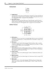
...VIEW 7 8 PAIR GROUP INPUT PATCH OUTPUT PATCH 9JKL A DATA button This button is selected. DM2000-Owner's Manual B DIO button This button is used to select the following pages: Oscillator, Channel Status Monitor, and Battery Check. E REMOTE button This button is used to select the following .../MTRX button This button selects the Aux/Mtrx Fader mode, in which the faders control Input or Output Channel levels, depending on page 231 for more information. See "Saving DM2000 Data to select the following pages: Word Clock Select, Dither, Cascade In, Cascade Out, Sampling Rate ...
...VIEW 7 8 PAIR GROUP INPUT PATCH OUTPUT PATCH 9JKL A DATA button This button is selected. DM2000-Owner's Manual B DIO button This button is used to select the following pages: Oscillator, Channel Status Monitor, and Battery Check. E REMOTE button This button is used to select the following .../MTRX button This button selects the Aux/Mtrx Fader mode, in which the faders control Input or Output Channel levels, depending on page 231 for more information. See "Saving DM2000 Data to select the following pages: Word Clock Select, Dither, Cascade In, Cascade Out, Sampling Rate ...

Owner's Manual
Page 23
...INTERNAL EFFECTS button This button is used to select the Input and Output Pair pages. See "Viewing Channel Parameter Settings" on page 124, "Viewing Channel Fader Settings" on page 125, and "Channel Library" on page 61 for more information. See "Output Patching" on page 155 for more ...button is used to select the following pages: Input Channel Patch, Input Channel Insert In Patch, Effects 1-2 Input Patch, Effects 3-8 Input Patch, Input Channel Name, and Input Patch Library. See "Editing GEQs" on page 63 for more information. DM2000-Owner's Manual H VIEW button This button is ...
...INTERNAL EFFECTS button This button is used to select the Input and Output Pair pages. See "Viewing Channel Parameter Settings" on page 124, "Viewing Channel Fader Settings" on page 125, and "Channel Library" on page 61 for more information. See "Output Patching" on page 155 for more ...button is used to select the following pages: Input Channel Patch, Input Channel Insert In Patch, Effects 1-2 Input Patch, Effects 3-8 Input Patch, Input Channel Name, and Input Patch Library. See "Editing GEQs" on page 63 for more information. DM2000-Owner's Manual H VIEW button This button is ...

Owner's Manual
Page 24
...PLUG-INS [1-8] button indicator flashes. A warning message appears if there's nothing inserted in the currently selected channel, the relevant Effects Edit or Plug-In Edit page appears when this button is pressed, and its indicator lights up or... the gain of parameters, rows being controlled by the Parameter Up/Down buttons. When the EFFECTS/PLUG-INS [CHANNEL INSERTS] button indicator is selected, they control the currently selected row of the selected band. When the Effects Edit... Edit page is displayed. The push switches are available, an up . DM2000-Owner's Manual
...PLUG-INS [1-8] button indicator flashes. A warning message appears if there's nothing inserted in the currently selected channel, the relevant Effects Edit or Plug-In Edit page appears when this button is pressed, and its indicator lights up or... the gain of parameters, rows being controlled by the Parameter Up/Down buttons. When the EFFECTS/PLUG-INS [CHANNEL INSERTS] button indicator is selected, they control the currently selected row of the selected band. When the Effects Edit... Edit page is displayed. The push switches are available, an up . DM2000-Owner's Manual

Owner's Manual
Page 25
... the right Tab Scroll arrow is displayed, is used to display the tabs of pages available to adjust the contrast of the currently selected page. DM2000-Owner's Manual See "Selecting Display Pages" on page 36 for more information. Display Section 1 Control Surface 11 2 3 4 F1 F2 F3 F4... 5 A Display This 320 x 240 dot display with fluorescent backlight displays pages, information on the currently selected Scene and channel, the sampling rate, and more information. See "About the Display" on page 36 for more . See "Selecting Display Pages" on page 35 for ...
... the right Tab Scroll arrow is displayed, is used to display the tabs of pages available to adjust the contrast of the currently selected page. DM2000-Owner's Manual See "Selecting Display Pages" on page 36 for more information. Display Section 1 Control Surface 11 2 3 4 F1 F2 F3 F4... 5 A Display This 320 x 240 dot display with fluorescent backlight displays pages, information on the currently selected Scene and channel, the sampling rate, and more information. See "About the Display" on page 36 for more . See "Selecting Display Pages" on page 35 for ...


