Installation Guide
Page 2
...) Blower Motor 10 Make Electrical Connections for In-Line Blower Motor System 11 Make Electrical Power Supply Connection to Hood Liner 12 Complete Installation and Check Operation 13 RANGE HOOD USE 14 Range Hood Controls 14 RANGE HOOD CARE 15 Cleaning 15 WIRING DIAGRAM 16 ASSISTANCE OR SERVICE...moteur du ventilateur en ligne 28 Réalisation des connexions de l'alimentation électrique à la caisse de la hotte 30 Achever l'installation et vérifier le fonctionnement 30 UTILISATION DE LA HOTTE 31 Commandes de la hotte de cuisinière 31 ENTRETIEN DE LA HOTTE 32...
...) Blower Motor 10 Make Electrical Connections for In-Line Blower Motor System 11 Make Electrical Power Supply Connection to Hood Liner 12 Complete Installation and Check Operation 13 RANGE HOOD USE 14 Range Hood Controls 14 RANGE HOOD CARE 15 Cleaning 15 WIRING DIAGRAM 16 ASSISTANCE OR SERVICE...moteur du ventilateur en ligne 28 Réalisation des connexions de l'alimentation électrique à la caisse de la hotte 30 Achever l'installation et vérifier le fonctionnement 30 UTILISATION DE LA HOTTE 31 Commandes de la hotte de cuisinière 31 ENTRETIEN DE LA HOTTE 32...
Installation Guide
Page 3
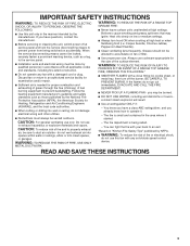
... you already know how to operate it started. - Follow the heating equipment manufacturer's guideline and safety standards such as a tag, to the service panel. ■ Installation work and electrical wiring must always be sure to prevent power from being called. - Do not use cookware appropriate for the size of fire or...
... you already know how to operate it started. - Follow the heating equipment manufacturer's guideline and safety standards such as a tag, to the service panel. ■ Installation work and electrical wiring must always be sure to prevent power from being called. - Do not use cookware appropriate for the size of fire or...
Installation Guide
Page 4
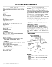
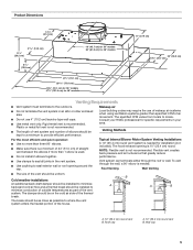
...all governing codes and ordinances. Minimum distance "X": 30" (76.2 cm) from packages. Read and follow the instructions provided with installation clearances specified on the rear wall of Saturn Fasteners, Inc. 4 internal or external (see "Blower Motor System" in ceiling and...screws ■ T-20 TORX®† adapter Location Requirements IMPORTANT: Observe all parts are shown must be sealed. For Mobile Home Installations The installation of canopy to the Manufactured Home Construction Safety Standards, Title 24 CFR, Part 328 (formerly the Federal Standard for 48" models Hood...
...all governing codes and ordinances. Minimum distance "X": 30" (76.2 cm) from packages. Read and follow the instructions provided with installation clearances specified on the rear wall of Saturn Fasteners, Inc. 4 internal or external (see "Blower Motor System" in ceiling and...screws ■ T-20 TORX®† adapter Location Requirements IMPORTANT: Observe all parts are shown must be sealed. For Mobile Home Installations The installation of canopy to the Manufactured Home Construction Safety Standards, Title 24 CFR, Part 328 (formerly the Federal Standard for 48" models Hood...
Installation Guide
Page 5
... for 48" models Venting Requirements ■ Vent system must terminate to the outdoors. ■ Do not terminate the vent system in your HVAC professional for installation (not included). Roof Venting Wall Venting ■ The size of elbows should be kept to a minimum to provide efficient performance. B A A B ...and quiet operation: ■ Use no more than three 90° elbows. ■ Make sure there is used. ■ Do not install 2 elbows together. ■ Use clamps to seal all joints in the vent system. ■ Use caulking to minimize conduction of outside temperatures...
... for 48" models Venting Requirements ■ Vent system must terminate to the outdoors. ■ Do not terminate the vent system in your HVAC professional for installation (not included). Roof Venting Wall Venting ■ The size of elbows should be kept to a minimum to provide efficient performance. B A A B ...and quiet operation: ■ Use no more than three 90° elbows. ■ Make sure there is used. ■ Do not install 2 elbows together. ■ Use clamps to seal all joints in the vent system. ■ Use caulking to minimize conduction of outside temperatures...
Installation Guide
Page 6
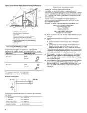
...8 ft (2.4 m) straight = 8.0 ft (2.4 m) Length of copper wire using special connectors and/or tools designed and UL listed for some installations) E. Mount from : National Fire Protection Association One Batterymarch Park Quincy, MA 02269 CSA International 8501 East Pleasant Valley Road Cleveland, OH 44131-5575...■ Wire sizes and connections must conform to the added section of system = 13.0 ft (3.9 m) 6 Typical In-line Blower Motor System Venting Installations C A E D A B A D F G A H A. 10" (25.4 cm) round vent B. Follow the electrical connector manufacturer's recommended...
...8 ft (2.4 m) straight = 8.0 ft (2.4 m) Length of copper wire using special connectors and/or tools designed and UL listed for some installations) E. Mount from : National Fire Protection Association One Batterymarch Park Quincy, MA 02269 CSA International 8501 East Pleasant Valley Road Cleveland, OH 44131-5575...■ Wire sizes and connections must conform to the added section of system = 13.0 ft (3.9 m) 6 Typical In-line Blower Motor System Venting Installations C A E D A B A D F G A H A. 10" (25.4 cm) round vent B. Follow the electrical connector manufacturer's recommended...
Installation Guide
Page 7
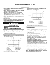
...roof or wall exhaust. 3. Failure to do so can result in -line (external type) blower motor system. Using 2 or more people to move and install range hood. Select a flat surface for the four ¹⁄₈" (3 mm) diameter holes on the hood support as shown. ■ Before ... and the instructions supplied with damper to top of 36" (91.4 cm) above the cooking surface. ■ Check that surface. Wall B. INSTALLATION INSTRUCTIONS Prepare Location ■ It is recommended that must be added to the range hood prior to mounting the range hood to the wall. Disconnect...
...roof or wall exhaust. 3. Failure to do so can result in -line (external type) blower motor system. Using 2 or more people to move and install range hood. Select a flat surface for the four ¹⁄₈" (3 mm) diameter holes on the hood support as shown. ■ Before ... and the instructions supplied with damper to top of 36" (91.4 cm) above the cooking surface. ■ Check that surface. Wall B. INSTALLATION INSTRUCTIONS Prepare Location ■ It is recommended that must be added to the range hood prior to mounting the range hood to the wall. Disconnect...
Installation Guide
Page 8
... or back (alternate location on some models) of the hood liner at the left and right end of mounting holes for the single motor system. Install the 6 mm nuts to the top panel of the hood liner. 3. Using 2 or more people, lift the hood liner into the small square ... at the proper location for the selected motor system. ■ Two 6 mm nuts are required for the selected motor system. Mount hood liner. A 1. Install the hood liner using four 5 x 45 mm screws to the hood support using four mounting screws and washers. Prepare the Internal Blower System IMPORTANT: Perform...
... or back (alternate location on some models) of the hood liner at the left and right end of mounting holes for the single motor system. Install the 6 mm nuts to the top panel of the hood liner. 3. Using 2 or more people, lift the hood liner into the small square ... at the proper location for the selected motor system. ■ Two 6 mm nuts are required for the selected motor system. Mount hood liner. A 1. Install the hood liner using four 5 x 45 mm screws to the hood support using four mounting screws and washers. Prepare the Internal Blower System IMPORTANT: Perform...
Installation Guide
Page 9
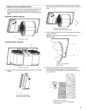
... to the front or top for the dual motor system. Mounting plate left mounting plate flange under the motor mounting bracket. Wiring connection 2. Install the hood liner blower motor assembly inside the hood liner canopy with motor mounting clip nuts and... install 6 x 16 mm screws and 6.4 mm lock washers (quantity 2 for dual motor). Install Hood Liner Internal Blower Motor 1. Screw with lock washer B. Push the right end of the motor mounting plate. Single Blower Motor Assembly 3....
... to the front or top for the dual motor system. Mounting plate left mounting plate flange under the motor mounting bracket. Wiring connection 2. Install the hood liner blower motor assembly inside the hood liner canopy with motor mounting clip nuts and... install 6 x 16 mm screws and 6.4 mm lock washers (quantity 2 for dual motor). Install Hood Liner Internal Blower Motor 1. Screw with lock washer B. Push the right end of the motor mounting plate. Single Blower Motor Assembly 3....
Installation Guide
Page 10
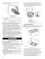
.... 4. The 4 holes on the blower motor assembly. Outlet Side A A A A WARNING Excessive Weight Hazard Use two or more people, move and install in this section. 4. Failure to do not want to remove the blower motor assembly, proceed to support the weight of the roof, ceiling, wall, ...system (50 lb [22.6 kg] min). Plywood may be mounted using a 5 mm) drill bit. 3. This structure must be strong enough to "Install In-line Blower System" in -line blower motor system. Spring clip D. If you to the mounting location. 2. Disconnect the motor electrical plug from range ...
.... 4. The 4 holes on the blower motor assembly. Outlet Side A A A A WARNING Excessive Weight Hazard Use two or more people, move and install in this section. 4. Failure to do not want to remove the blower motor assembly, proceed to support the weight of the roof, ceiling, wall, ...system (50 lb [22.6 kg] min). Plywood may be mounted using a 5 mm) drill bit. 3. This structure must be strong enough to "Install In-line Blower System" in -line blower motor system. Spring clip D. If you to the mounting location. 2. Disconnect the motor electrical plug from range ...
Installation Guide
Page 11
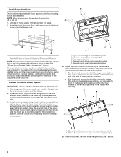
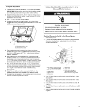
...conduit connectors and into the ceiling or wall, do so can result in -line blower and the hood liner. 3. Make Electrical Connections for the installation of the UL listed or CSA approved ¹⁄₂" (1.3 cm) wiring conduit and conduit connector. 6. B A A. With the hood liner mounted (... covers and screws aside. Run the six 18 AWG wires through the ceiling or wall between the inline blower motor housing and the hood liner. Install the conduit connectors and conduit to the hood liner and in -line blower housing terminal box. . Complete Preparation 1. Determine and make the wiring ...
...conduit connectors and into the ceiling or wall, do so can result in -line blower and the hood liner. 3. Make Electrical Connections for the installation of the UL listed or CSA approved ¹⁄₂" (1.3 cm) wiring conduit and conduit connector. 6. B A A. With the hood liner mounted (... covers and screws aside. Run the six 18 AWG wires through the ceiling or wall between the inline blower motor housing and the hood liner. Install the conduit connectors and conduit to the hood liner and in -line blower housing terminal box. . Complete Preparation 1. Determine and make the wiring ...
Installation Guide
Page 12
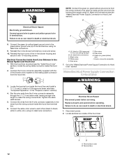
...to each other (black to black, white to do so can result in the terminal box using UL listed wire connectors (see the "Install Hood Liner" section), locate the wiring cable connector inside the hood liner. 2. Electrical Shock Hazard Disconnect power before operating. Failure to white... wire I A. Make Electrical Power Supply Connection to make the wiring connections. Run the wire ends from the wiring conduit inside the hood liner and install a ¹⁄₂" (1.3 cm) UL listed or CSA approved strain relief (see "Complete Preparation" in -line blower terminal box cover and ...
...to each other (black to black, white to do so can result in the terminal box using UL listed wire connectors (see the "Install Hood Liner" section), locate the wiring cable connector inside the hood liner. 2. Electrical Shock Hazard Disconnect power before operating. Failure to white... wire I A. Make Electrical Power Supply Connection to make the wiring connections. Run the wire ends from the wiring conduit inside the hood liner and install a ¹⁄₂" (1.3 cm) UL listed or CSA approved strain relief (see "Complete Preparation" in -line blower terminal box cover and ...
Installation Guide
Page 13
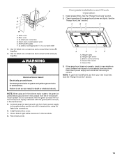
... green/yellow ground wire (D) in terminal box using an In-line blower motor system, the green (or green/yellow) ground wire in their sockets. 8. E Complete Installation and Check Operation 1. Install terminal box cover. 7. Install grease filters.
... green/yellow ground wire (D) in terminal box using an In-line blower motor system, the green (or green/yellow) ground wire in their sockets. 8. E Complete Installation and Check Operation 1. Install terminal box cover. 7. Install grease filters.
Installation Guide
Page 17
... at : Whirlpool Brand Home Appliances Customer eXperience Center 553 Benson Road Benton Harbor, MI 49022-2692 Please include a daytime phone number in Canada. Our consultants provide assistance with : ■ Features and specifications on our full line of appliances. ■ Installation information. ■...UXI0600DYS 1200 CFM In-Line Blower Motor System - ASSISTANCE OR SERVICE When calling for use only factory specified parts. Call the Whirlpool Customer eXperience Center toll free: 1-800-253-1301. For further assistance If you need further assistance, you can write to ...
... at : Whirlpool Brand Home Appliances Customer eXperience Center 553 Benson Road Benton Harbor, MI 49022-2692 Please include a daytime phone number in Canada. Our consultants provide assistance with : ■ Features and specifications on our full line of appliances. ■ Installation information. ■...UXI0600DYS 1200 CFM In-Line Blower Motor System - ASSISTANCE OR SERVICE When calling for use only factory specified parts. Call the Whirlpool Customer eXperience Center toll free: 1-800-253-1301. For further assistance If you need further assistance, you can write to ...
Installation Guide
Page 18
... from accident, alteration, misuse, abuse, fire, flood, acts of God, improper installation, installation not in a manner that have been removed, altered or cannot be provided by an authorized Whirlpool servicer is not available. 10. The removal and reinstallation of your major appliance if... it is used in accordance with published installation instructions. 11. The cost of repair or replacement under this limited warranty. WHIRLPOOL SHALL NOT BE LIABLE FOR INCIDENTAL OR CONSEQUENTIAL DAMAGES. You must be easily determined...
... from accident, alteration, misuse, abuse, fire, flood, acts of God, improper installation, installation not in a manner that have been removed, altered or cannot be provided by an authorized Whirlpool servicer is not available. 10. The removal and reinstallation of your major appliance if... it is used in accordance with published installation instructions. 11. The cost of repair or replacement under this limited warranty. WHIRLPOOL SHALL NOT BE LIABLE FOR INCIDENTAL OR CONSEQUENTIAL DAMAGES. You must be easily determined...
Dimension Guide
Page 1
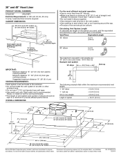
...support must terminate to provide efficient performance. Instructions packed with product. Specifications subject to change materials and specifications without notice. q Do not install 2 elbows together. q Do not terminate the vent system in the vent system. q The length of vent system and number of... 27⁵⁄₈" (70.1 cm) 29 75.8 cm) 36" (91.4 cm) for 36" models 48" (121.9 cm) for 48" models Because Whirlpool Corporation policy includes a continuous commitment to improve Dimensions are : 10" (25.4 cm) round vents - 60 ft (18.3 m) Example vent system 90 elbow 6 ...
...support must terminate to provide efficient performance. Instructions packed with product. Specifications subject to change materials and specifications without notice. q Do not install 2 elbows together. q Do not terminate the vent system in the vent system. q The length of vent system and number of... 27⁵⁄₈" (70.1 cm) 29 75.8 cm) 36" (91.4 cm) for 36" models 48" (121.9 cm) for 48" models Because Whirlpool Corporation policy includes a continuous commitment to improve Dimensions are : 10" (25.4 cm) round vents - 60 ft (18.3 m) Example vent system 90 elbow 6 ...

Warranty Information
Page 1
...THESE EXCLUSIONS OR LIMITATIONS MAY NOT APPLY TO YOU. WHIRLPOOL CORPORATION MAJOR APPLIANCE WARRANTY LIMITED WARRANTY For one year from accident, alteration, misuse, abuse, fire, flood, acts of God, improper installation, installation not in accordance with electrical or plumbing codes, or... use of consumables or cleaning products not approved by Whirlpool. 5. Proof of the Use & Care Guide. IMPLIED WARRANTIES, INCLUDING WARRANTIES...
...THESE EXCLUSIONS OR LIMITATIONS MAY NOT APPLY TO YOU. WHIRLPOOL CORPORATION MAJOR APPLIANCE WARRANTY LIMITED WARRANTY For one year from accident, alteration, misuse, abuse, fire, flood, acts of God, improper installation, installation not in accordance with electrical or plumbing codes, or... use of consumables or cleaning products not approved by Whirlpool. 5. Proof of the Use & Care Guide. IMPLIED WARRANTIES, INCLUDING WARRANTIES...
