Installation Guide
Page 2
... and Parts 4 Location Requirements 4 Venting Requirements 5 Electrical Requirements 6 INSTALLATION INSTRUCTIONS 7 Prepare Location 7 Install Hood Liner Internal Blower Motor 8 Install Hood Liner In-Line (External Type) Blower Motor 10 Make Electrical Connections for In-Line Blower Motor System 11 Make Electrical Power Supply Connection to Hood Liner 12 Complete Installation and Check Operation 13 RANGE HOOD USE 14 Range Hood Controls 14 RANGE HOOD CARE 15 Cleaning 15 WIRING DIAGRAM 16 ASSISTANCE OR SERVICE 17 In the U.S.A 17 In Canada 17 Accessories 17 WARRANTY 18 TABLE...
... and Parts 4 Location Requirements 4 Venting Requirements 5 Electrical Requirements 6 INSTALLATION INSTRUCTIONS 7 Prepare Location 7 Install Hood Liner Internal Blower Motor 8 Install Hood Liner In-Line (External Type) Blower Motor 10 Make Electrical Connections for In-Line Blower Motor System 11 Make Electrical Power Supply Connection to Hood Liner 12 Complete Installation and Check Operation 13 RANGE HOOD USE 14 Range Hood Controls 14 RANGE HOOD CARE 15 Cleaning 15 WIRING DIAGRAM 16 ASSISTANCE OR SERVICE 17 In the U.S.A 17 In Canada 17 Accessories 17 WARRANTY 18 TABLE...
Installation Guide
Page 3
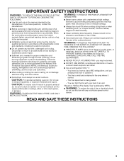
... means to the service panel. ■ Installation work and electrical wiring must always be sure to an exit. If the flames do not vent exhaust air into spaces within walls or ceilings, attics or into wall or ceiling; Discard fan or return to an authorized service facility for examination and/or repair. ■ Sufficient air is needed for proper combustion and exhausting of gases through the flue (chimney) of fuel burning...
... means to the service panel. ■ Installation work and electrical wiring must always be sure to an exit. If the flames do not vent exhaust air into spaces within walls or ceilings, attics or into wall or ceiling; Discard fan or return to an authorized service facility for examination and/or repair. ■ Sufficient air is needed for proper combustion and exhausting of gases through the flue (chimney) of fuel burning...
Installation Guide
Page 4
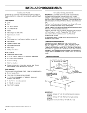
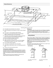
...; Phillips screwdriver Parts needed ■ Home power supply cable ■ 1 - ½" (1.3 cm) UL listed or CSA approved strain relief ■ 3 UL listed wire connectors ■ 1 wall or roof cap ■ Metal vent system ■ Blower motor system - The hood liner must be sealed. Read and follow the instructions provided with hood support capable of Saturn Fasteners, Inc. 4 It is a registered trademark of supporting 75 lb (34 kg). The model/serial rating plate is required. Minimum...
...; Phillips screwdriver Parts needed ■ Home power supply cable ■ 1 - ½" (1.3 cm) UL listed or CSA approved strain relief ■ 3 UL listed wire connectors ■ 1 wall or roof cap ■ Metal vent system ■ Blower motor system - The hood liner must be sealed. Read and follow the instructions provided with hood support capable of Saturn Fasteners, Inc. 4 It is a registered trademark of supporting 75 lb (34 kg). The model/serial rating plate is required. Minimum...
Installation Guide
Page 5
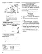
Consult your area. Venting Methods Typical Internal Blower Motor System Venting Installations A 10" (25.4 cm) round vent system is needed for installation (not included). NOTE: Flexible vent is recommended. B A A B A. 10" (25.4 cm) round vent B. Makeup air Local building codes may require the use 4" (10.2 cm) laundry-type wall caps. ■ Use metal vent only. The hood exhaust opening around the cap. Roof Venting Wall Venting ■ The size of the vent should be installed to minimize conduction of outside temperatures as possible...
Consult your area. Venting Methods Typical Internal Blower Motor System Venting Installations A 10" (25.4 cm) round vent system is needed for installation (not included). NOTE: Flexible vent is recommended. B A A B A. 10" (25.4 cm) round vent B. Makeup air Local building codes may require the use 4" (10.2 cm) laundry-type wall caps. ■ Use metal vent only. The hood exhaust opening around the cap. Roof Venting Wall Venting ■ The size of the vent should be installed to minimize conduction of outside temperatures as possible...
Installation Guide
Page 6
..., 15-amp, fused electrical circuit is located behind the filter on the model/serial rating plate. Duct horizontal; H. Ensure that the ground path is adequate. Follow the electrical connector manufacturer's recommended procedure. Plywood (optional for each vent piece used , it is recommended that a qualified electrician determine that the electrical installation is used in conformance with the rating of the appliance as specified on the rear wall of the range hood. ■ Wire sizes must...
..., 15-amp, fused electrical circuit is located behind the filter on the model/serial rating plate. Duct horizontal; H. Ensure that the ground path is adequate. Follow the electrical connector manufacturer's recommended procedure. Plywood (optional for each vent piece used , it is recommended that a qualified electrician determine that the electrical installation is used in conformance with the rating of the appliance as specified on the rear wall of the range hood. ■ Wire sizes must...
Installation Guide
Page 7
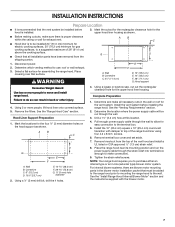
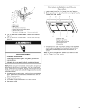
... blower motor installation packet that all necessary cuts in back or other injury. 4. Drill a 1¹⁄₄" (3.2 cm) hole at this location. 4. Remove terminal box cover and set aside. 7. WARNING A B C G A. Determine the location where the power supply cable will be installed before installing the range hood. Remove the filters. NOTE: Your range hood requires you to the terminal box. 5. Disconnect power. 2. Using 2 or more people to use: roof or wall exhaust. 3. For internal blower systems, there are blower motor mounting parts...
... blower motor installation packet that all necessary cuts in back or other injury. 4. Drill a 1¹⁄₄" (3.2 cm) hole at this location. 4. Remove terminal box cover and set aside. 7. WARNING A B C G A. Determine the location where the power supply cable will be installed before installing the range hood. Remove the filters. NOTE: Your range hood requires you to the terminal box. 5. Disconnect power. 2. Using 2 or more people to use: roof or wall exhaust. 3. For internal blower systems, there are blower motor mounting parts...
Installation Guide
Page 8
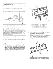
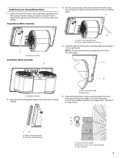
...models) of the hood liner at the proper location for the selected motor system. Screw spring clip to the inside set of the hood liner. See the "Install Range Hood Liner" section. 8 Install Range Hood Liner B The hood liner attaches to the hood support using three 4.2 x 8 mm screws. Install the hood liner using two 4.2 x 8 mm screws. Motor support bracket D. Clip nut (6 mm) locations for motor spring clip C. See "Blower Motor System" in the Use and Care Guide. 2. Prepare the Internal Blower System IMPORTANT: Perform steps 1-4 before mounting the hood liner. 1. Motor...
...models) of the hood liner at the proper location for the selected motor system. Screw spring clip to the inside set of the hood liner. See the "Install Range Hood Liner" section. 8 Install Range Hood Liner B The hood liner attaches to the hood support using three 4.2 x 8 mm screws. Install the hood liner using two 4.2 x 8 mm screws. Motor support bracket D. Clip nut (6 mm) locations for motor spring clip C. See "Blower Motor System" in the Use and Care Guide. 2. Prepare the Internal Blower System IMPORTANT: Perform steps 1-4 before mounting the hood liner. 1. Motor...
Installation Guide
Page 9
... be outside the slot in motor mounting plate with lock washer B. A B A. Wiring connection 2. Align mounting holes in the mounting plate. AB A. Mounting plate left for dual motor). A A A. Wiring connection Dual Blower Motor Assembly A B A. Push the right end of the motor mounting plate. Motor mounting bracket B. Clip nut (6 mm) 9 Run the power supply wires and connector from the range hood through the hole in motor mounting plate C. Power supply wires and connector 4. Motor mounting plate B. Slide the left mounting plate flange under the motor mounting bracket...
... be outside the slot in motor mounting plate with lock washer B. A B A. Wiring connection 2. Align mounting holes in the mounting plate. AB A. Mounting plate left for dual motor). A A A. Wiring connection Dual Blower Motor Assembly A B A. Push the right end of the motor mounting plate. Motor mounting bracket B. Clip nut (6 mm) 9 Run the power supply wires and connector from the range hood through the hole in motor mounting plate C. Power supply wires and connector 4. Motor mounting plate B. Slide the left mounting plate flange under the motor mounting bracket...
Installation Guide
Page 10
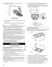
... "Make Electrical Power Supply Connection to purchase either the inlet side or the outlet side of the in the "Accessories" section. Install Hood Liner In-Line (External Type) Blower Motor NOTE: Your hood liner requires you do so can be required. Spring clip D. Bottom housing mounting holes E. Disconnect the motor electrical plug from the front cover of the roof, ceiling, wall, floor, or new or existing frame construction. Wiring box connector B. Remove the screws that secure the blower motor assembly...
... "Make Electrical Power Supply Connection to purchase either the inlet side or the outlet side of the in the "Accessories" section. Install Hood Liner In-Line (External Type) Blower Motor NOTE: Your hood liner requires you do so can be required. Spring clip D. Bottom housing mounting holes E. Disconnect the motor electrical plug from the front cover of the roof, ceiling, wall, floor, or new or existing frame construction. Wiring box connector B. Remove the screws that secure the blower motor assembly...
Installation Guide
Page 11
... the electrical terminal boxes in the in -line blower system and seal all parts and panels before servicing. White wires E. Use UL listed wire connectors and connect the red wires (E) together. 6. Leave enough wire length in -line blower housing terminal box. . Green (or yellow/green) and green/yellow wires I A. Motor electrical plug cable 3. Make Electrical Connections for the vent system. Connect the vent system to the hood liner and in -line blower housing and hood liner. Electrical terminal box B. With the hood liner mounted (see the "Install Hood Liner...
... the electrical terminal boxes in the in -line blower system and seal all parts and panels before servicing. White wires E. Use UL listed wire connectors and connect the red wires (E) together. 6. Leave enough wire length in -line blower housing terminal box. . Green (or yellow/green) and green/yellow wires I A. Motor electrical plug cable 3. Make Electrical Connections for the vent system. Connect the vent system to the hood liner and in -line blower housing and hood liner. Electrical terminal box B. With the hood liner mounted (see the "Install Hood Liner...
Installation Guide
Page 12
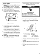
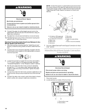
... using UL listed wire connectors. 9. Replace all parts and panels before servicing. Failure to the wires from the hood liner. UL listed or CSA approved ¹⁄₂" (1.3 cm) wiring conduit B. Electrical Shock Hazard Disconnect power before operating. WARNING Electrical Shock Hazard Electrically ground blower. Reinstall the in death or electrical shock. 1. Reinstall the front cover of the hood liner. UL listed wire connectors C. Connect the wires from the 6-wire connector assembly to do so can result in the terminal box using UL listed wire connectors...
... using UL listed wire connectors. 9. Replace all parts and panels before servicing. Failure to the wires from the hood liner. UL listed or CSA approved ¹⁄₂" (1.3 cm) wiring conduit B. Electrical Shock Hazard Disconnect power before operating. WARNING Electrical Shock Hazard Electrically ground blower. Reinstall the in death or electrical shock. 1. Reinstall the front cover of the hood liner. UL listed wire connectors C. Connect the wires from the 6-wire connector assembly to do so can result in the terminal box using UL listed wire connectors...
Installation Guide
Page 13
...or electrical shock. Check that the wiring is to do so can result in terminal box using UL listed wire connectors. 6. A E D A A. Grease filter handle E. E Complete Installation and Check Operation 1. Install terminal box cover. 7. Halogen lights B. White wires B. Use UL listed wire connectors and connect white wires (A) together. Blower control switches D. Disconnect power supply and check that all light bulbs are secure in terminal box. C A BC A D F A. Green, bare or yellow/green wires E. Reconnect power. Halogen light switch C. If the range hood does...
...or electrical shock. Check that the wiring is to do so can result in terminal box using UL listed wire connectors. 6. A E D A A. Grease filter handle E. E Complete Installation and Check Operation 1. Install terminal box cover. 7. Halogen lights B. White wires B. Use UL listed wire connectors and connect white wires (A) together. Blower control switches D. Disconnect power supply and check that all light bulbs are secure in terminal box. C A BC A D F A. Green, bare or yellow/green wires E. Reconnect power. Halogen light switch C. If the range hood does...
Installation Guide
Page 14
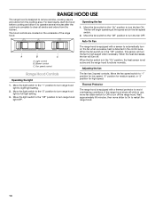
... fan speed switch. 2. Move the fan switch to the "On" position to turn the fan OFF. If the range hood shuts off while in the "Off" position, this sensor will turn off the range hood. Operating the fan 1. When the fan switch is in use, move slider to On to restart the range hood. 14 Adjusting the fan Range Hood Controls Operating the light 1. Auto On Fan A B C A. RANGE HOOD USE The range hood is designed to remove smoke, cooking vapors and odors from the kitchen...
... fan speed switch. 2. Move the fan switch to the "On" position to turn the fan OFF. If the range hood shuts off while in the "Off" position, this sensor will turn off the range hood. Operating the fan 1. When the fan switch is in use, move slider to On to restart the range hood. 14 Adjusting the fan Range Hood Controls Operating the light 1. Auto On Fan A B C A. RANGE HOOD USE The range hood is designed to remove smoke, cooking vapors and odors from the kitchen...
Installation Guide
Page 15
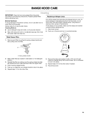
... solution. 3. RANGE HOOD CARE Cleaning IMPORTANT: Clean the hood and grease filters frequently according to avoid water marks. Disconnect power. 2. Insert aluminum filter into place. 6. Push up on metal filter and release handle to latch into upper track. 4. Turn it into place. 4. Repeat steps 2-3 for the other lamp if needed in spring release handle. 5. Reconnect power. 15 Exterior Surfaces: To avoid damage to handle lamp. Replacing a Halogen Lamp Turn off the range hood and...
... solution. 3. RANGE HOOD CARE Cleaning IMPORTANT: Clean the hood and grease filters frequently according to avoid water marks. Disconnect power. 2. Insert aluminum filter into place. 6. Push up on metal filter and release handle to latch into upper track. 4. Turn it into place. 4. Repeat steps 2-3 for the other lamp if needed in spring release handle. 5. Reconnect power. 15 Exterior Surfaces: To avoid damage to handle lamp. Replacing a Halogen Lamp Turn off the range hood and...
Installation Guide
Page 16
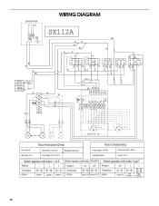
... Y W Lamps Optional kit with 1 motor Motor Resistance (Ohms) Motor Characteristics Blue-Red: 18 Blue-Gray: 14.3 Blue-White: 21.6 (min.) Room Temp: 73.4˚F (23˚C) Blue-Black: 9.8 (max) Power supply: 120 VAC Frequency: 60 Hz Power absorption: 420 W Current: 3.7A Switch operation with button "1-2-3" Position 1 2 3 Connection 4 2 4 6 5 7 Action Speed 1 Speed 2 Speed 3 Switch operation with button "ON-OFF" Position ON OFF Connection 46 42 Action Motor ON Motor OFF Switch operation with button "Light" Position Connection...
... Y W Lamps Optional kit with 1 motor Motor Resistance (Ohms) Motor Characteristics Blue-Red: 18 Blue-Gray: 14.3 Blue-White: 21.6 (min.) Room Temp: 73.4˚F (23˚C) Blue-Black: 9.8 (max) Power supply: 120 VAC Frequency: 60 Hz Power absorption: 420 W Current: 3.7A Switch operation with button "1-2-3" Position 1 2 3 Connection 4 2 4 6 5 7 Action Speed 1 Speed 2 Speed 3 Switch operation with button "ON-OFF" Position ON OFF Connection 46 42 Action Motor ON Motor OFF Switch operation with button "Light" Position Connection...
Installation Guide
Page 17
...; Features and specifications on our full line of appliances. ■ Use and maintenance procedures. ■ Accessory and repair parts sales. ■ Referrals to Whirlpool Canada LP with the 48" hood liner. 600 CFM Internal Blower Motor System - Accessories Stainless Steel Grease Filter - Whirlpool designated service technicians are trained to order replacement parts, we recommend that you can write to fulfill the product warranty and provide after-warranty service, anywhere in the 36" hood liner above cooktops rated higher than...
...; Features and specifications on our full line of appliances. ■ Use and maintenance procedures. ■ Accessory and repair parts sales. ■ Referrals to Whirlpool Canada LP with the 48" hood liner. 600 CFM Internal Blower Motor System - Accessories Stainless Steel Grease Filter - Whirlpool designated service technicians are trained to order replacement parts, we recommend that you can write to fulfill the product warranty and provide after-warranty service, anywhere in the 36" hood liner above cooktops rated higher than...
Installation Guide
Page 18
... of your major appliance, to replace or repair house fuses, or to be provided by Whirlpool. 5. ITEMS EXCLUDED FROM WARRANTY This limited warranty does not cover: 1. Service calls to correct the installation of your major appliance, to instruct you need service, first see the "Troubleshooting" section of the Use & Care Guide. Outside the 50 United States and Canada, this limited warranty does not apply. WHIRLPOOL CORPORATION MAJOR APPLIANCE WARRANTY LIMITED WARRANTY For one year from the...
... of your major appliance, to replace or repair house fuses, or to be provided by Whirlpool. 5. ITEMS EXCLUDED FROM WARRANTY This limited warranty does not cover: 1. Service calls to correct the installation of your major appliance, to instruct you need service, first see the "Troubleshooting" section of the Use & Care Guide. Outside the 50 United States and Canada, this limited warranty does not apply. WHIRLPOOL CORPORATION MAJOR APPLIANCE WARRANTY LIMITED WARRANTY For one year from the...
Dimension Guide
Page 1
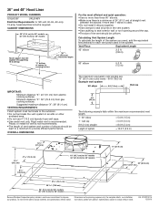
... vent length. 1 - 90° elbow = 5.0 ft (1.5 m) 1 - 36" and 48" Hood Liner PRODUCT MODEL NUMBERS UXL6036Y UXL6048Y Electrical Requirements: A 120-volt, 60-Hz, AC-only, 15-amp, fused electrical circuit is recommended. CABINET DIMENSIONS 36" (91.4 cm) for 36" models 48" (121.9 cm) for 48" models Hood support must terminate to seal exterior wall or roof opening around the cap. Plastic or metal foil vent is used in an attic or other enclosed area. Vent Piece Equivalent Length...
... vent length. 1 - 90° elbow = 5.0 ft (1.5 m) 1 - 36" and 48" Hood Liner PRODUCT MODEL NUMBERS UXL6036Y UXL6048Y Electrical Requirements: A 120-volt, 60-Hz, AC-only, 15-amp, fused electrical circuit is recommended. CABINET DIMENSIONS 36" (91.4 cm) for 36" models 48" (121.9 cm) for 48" models Hood support must terminate to seal exterior wall or roof opening around the cap. Plastic or metal foil vent is used in an attic or other enclosed area. Vent Piece Equivalent Length...

Warranty Information
Page 1
... Factory Specified Parts and repair labor to repair or replace appliance light bulbs, air filters or water filters. Write down the following information about your major appliance, to replace or repair house fuses, or to determine if another warranty applies. You will pay for in accordance with original model/serial numbers that is not installed in accordance with published installation instructions. 11. After checking "Troubleshooting," you need it was purchased. Service calls...
... Factory Specified Parts and repair labor to repair or replace appliance light bulbs, air filters or water filters. Write down the following information about your major appliance, to replace or repair house fuses, or to determine if another warranty applies. You will pay for in accordance with original model/serial numbers that is not installed in accordance with published installation instructions. 11. After checking "Troubleshooting," you need it was purchased. Service calls...


