Warranty Information
Page 1
.... Repairs when your major appliance to better help by checking the "Assistance or Service" section or by calling Whirlpool. Major appliances with published installation instructions. 11. The cost of repair or replacement under this limited warranty. IMPLIED WARRANTIES, INCLUDING WARRANTIES OF MERCHANTABILITY.... 7. The removal and reinstallation of your major appliance is located in a remote area where service by an authorized Whirlpool servicer is not installed in -home service is covered by this warranty. 8. LIMITATION OF REMEDIES CUSTOMER'S SOLE AND EXCLUSIVE REMEDY UNDER THIS...
.... Repairs when your major appliance to better help by checking the "Assistance or Service" section or by calling Whirlpool. Major appliances with published installation instructions. 11. The cost of repair or replacement under this limited warranty. IMPLIED WARRANTIES, INCLUDING WARRANTIES OF MERCHANTABILITY.... 7. The removal and reinstallation of your major appliance is located in a remote area where service by an authorized Whirlpool servicer is not installed in -home service is covered by this warranty. 8. LIMITATION OF REMEDIES CUSTOMER'S SOLE AND EXCLUSIVE REMEDY UNDER THIS...
Installation Guide
Page 2
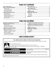
...appliance. TABLE OF CONTENTS VENT SYSTEM SAFETY 2 INSTALLATION REQUIREMENTS 4 Tools and Parts 4 Location Requirements 4 Electrical Requirements 7 Venting Requirements 7 INSTALLATION INSTRUCTIONS 8 Venting Methods 8 Install Vent System 9 Rear Mounting - Blower Motor 11 Complete Installation 12 Make Electrical Connections 13 Check Operation 13 VENT...TABLE DES MATIÈRES SÉCURITÉ DU SYSTÈME DE VENTILATION 19 EXIGENCES D'INSTALLATION 21 Outils et pièces 21 Exigences d'emplacement 21 Spécifications électriques 24 Exigences concernant l'é...
...appliance. TABLE OF CONTENTS VENT SYSTEM SAFETY 2 INSTALLATION REQUIREMENTS 4 Tools and Parts 4 Location Requirements 4 Electrical Requirements 7 Venting Requirements 7 INSTALLATION INSTRUCTIONS 8 Venting Methods 8 Install Vent System 9 Rear Mounting - Blower Motor 11 Complete Installation 12 Make Electrical Connections 13 Check Operation 13 VENT...TABLE DES MATIÈRES SÉCURITÉ DU SYSTÈME DE VENTILATION 19 EXIGENCES D'INSTALLATION 21 Outils et pièces 21 Exigences d'emplacement 21 Spécifications électriques 24 Exigences concernant l'é...
Installation Guide
Page 3
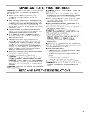
... exhaust air, be allowed to duct air outside - The fire department is needed for the size of fuel burning equipment to the service panel. ■ Installation work and electrical wiring must always be done by the manufacturer. WARNING: TO REDUCE THE RISK OF FIRE, USE ONLY METAL DUCTWORK. BE CAREFUL TO...
... exhaust air, be allowed to duct air outside - The fire department is needed for the size of fuel burning equipment to the service panel. ■ Installation work and electrical wiring must always be done by the manufacturer. WARNING: TO REDUCE THE RISK OF FIRE, USE ONLY METAL DUCTWORK. BE CAREFUL TO...
Installation Guide
Page 4
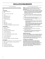
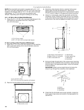
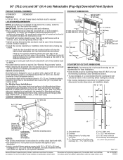
... cabinet walls, backsplash, and rear wall studs inside the cabinet. See the "Countertop Cutout Dimensions Chart." For Mobile Home Installations The installation of this downdraft vent must be sealed. ■ Grounded electrical outlet is not applicable, the standard for the minimum distance... tools and parts before making any tools listed here. Given dimensions provide minimum clearance. ■ Consult the cooktop manufacturer installation instructions before starting installation. Check that are shown must be 18" (45.7 cm) above the terminal box cover. ■ Downdraft vent ...
... cabinet walls, backsplash, and rear wall studs inside the cabinet. See the "Countertop Cutout Dimensions Chart." For Mobile Home Installations The installation of this downdraft vent must be sealed. ■ Grounded electrical outlet is not applicable, the standard for the minimum distance... tools and parts before making any tools listed here. Given dimensions provide minimum clearance. ■ Consult the cooktop manufacturer installation instructions before starting installation. Check that are shown must be 18" (45.7 cm) above the terminal box cover. ■ Downdraft vent ...
Installation Guide
Page 6
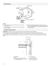
...8324;" x 10" (8.3 x 25.4 cm) rectangular or 6" (15.2 cm) round vent system. Countertop Cutout Dimensions IMPORTANT: Countertops with your specific installation. Downdraft vent B. Countertop and backsplash I A. Cabinet Dimension A 12.7 mm) minimum 10" (25.4 cm) 21 54.1 cm) 21 54.1 ...the cooktop and vent cutouts be drawn on your cooktop for vent system cutout location that came with a bull-nosed front edge are for these installations. Locate power supply junction box at lower left hand rear corner of cooktop rear overhang D. Some models require a countertop deeper than 25" ...
...8324;" x 10" (8.3 x 25.4 cm) rectangular or 6" (15.2 cm) round vent system. Countertop Cutout Dimensions IMPORTANT: Countertops with your specific installation. Downdraft vent B. Countertop and backsplash I A. Cabinet Dimension A 12.7 mm) minimum 10" (25.4 cm) 21 54.1 cm) 21 54.1 ...the cooktop and vent cutouts be drawn on your cooktop for vent system cutout location that came with a bull-nosed front edge are for these installations. Locate power supply junction box at lower left hand rear corner of cooktop rear overhang D. Some models require a countertop deeper than 25" ...
Installation Guide
Page 7
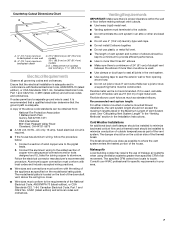
...No. 0-M91 (latest edition) and all local codes and ordinances. Recommended vent system length: For either interior-mounted or exterior-mounted blower installations, the vent system length should be on 36" (91.4 cm) models D. Flexible metal vent is proper clearance within the wall or ...to where the vent system enters the heated portion of the house. If it is recommended that a qualified electrician determine that the electrical installation is required. ■ If the house has aluminum wiring, follow the procedure below: 1. The specified CFM varies from : National Fire...
...No. 0-M91 (latest edition) and all local codes and ordinances. Recommended vent system length: For either interior-mounted or exterior-mounted blower installations, the vent system length should be on 36" (91.4 cm) models D. Flexible metal vent is proper clearance within the wall or ...to where the vent system enters the heated portion of the house. If it is recommended that a qualified electrician determine that the electrical installation is required. ■ If the house has aluminum wiring, follow the procedure below: 1. The specified CFM varies from : National Fire...

Installation Guide
Page 8
... can be mounted for right or left venting if needed . Down vent NOTE: For island locations, a front- INSTALLATION INSTRUCTIONS Venting Methods Determine which venting method is required from the blower motor box. Vent System Installed Under a Concrete Slab Using PVC Sewer Pipe Island Location Front (Standard)-Mounted Blower Motor Rear-Mounted Blower...
... can be mounted for right or left venting if needed . Down vent NOTE: For island locations, a front- INSTALLATION INSTRUCTIONS Venting Methods Determine which venting method is required from the blower motor box. Vent System Installed Under a Concrete Slab Using PVC Sewer Pipe Island Location Front (Standard)-Mounted Blower Motor Rear-Mounted Blower...
Installation Guide
Page 9
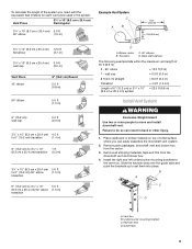
... draft damper The following example falls within the maximum vent length of 6" (15.2 cm) or 3¹⁄₄" x 10" = 22.5 ft (6.8 m) (8.3 cm x 25.4 cm) system Install Vent System WARNING Excessive Weight Hazard Use two or more people to the vent box...
... draft damper The following example falls within the maximum vent length of 6" (15.2 cm) or 3¹⁄₄" x 10" = 22.5 ft (6.8 m) (8.3 cm x 25.4 cm) system Install Vent System WARNING Excessive Weight Hazard Use two or more people to the vent box...
Installation Guide
Page 10
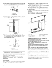
...to the motor box. C A Dim. Motor box B. Support leg C. 4 x 8 mm screws (4) Determine Which Vent Direction Is Best For Your Installation When installed in a cabinet, vent system can exhaust through the bottom, right or left of the motor box and set them aside. Cover plate B. Remove 4 ...of the motor box that hold the motor assembly to the face of the cabinet. NOTE: Reinstall the electrical wiring connection to the "Complete Installation" section. 10 Otherwise, go to motor if removed. 8. Measure distance "X" from the bottom of the countertop. Blower Motor" section. Using...
...to the motor box. C A Dim. Motor box B. Support leg C. 4 x 8 mm screws (4) Determine Which Vent Direction Is Best For Your Installation When installed in a cabinet, vent system can exhaust through the bottom, right or left of the motor box and set them aside. Cover plate B. Remove 4 ...of the motor box that hold the motor assembly to the face of the cabinet. NOTE: Reinstall the electrical wiring connection to the "Complete Installation" section. 10 Otherwise, go to motor if removed. 8. Measure distance "X" from the bottom of the countertop. Blower Motor" section. Using...

Installation Guide
Page 11
... wire mounting plate to the "Complete Installation" section. 11 Place the keyhole slots over the 2 shoulder screws on the rear of the vent box and reconnect the wire connection to vent box ...
... wire mounting plate to the "Complete Installation" section. 11 Place the keyhole slots over the 2 shoulder screws on the rear of the vent box and reconnect the wire connection to vent box ...
Installation Guide
Page 12
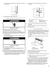
Remove the appropriate knockout from the front or rear panel and install a ¹⁄₂" (12.7 mm) UL listed or CSA approved conduit connector. 4. Position downdraft vent so it is supplied with a 3¹⁄₄" x 10" (8.3 x 25.4 ... 6. Terminal box cover 12 Using 2 or more people, insert the downdraft vent into the underside of the countertop. Cabinet back E. Cabinet floor G. Countertop 5. Backsplash C. Complete Installation NOTE: The downdraft vent system is centered in the cutout with the rear flange over the edge of the cutout and the rear of the...
Remove the appropriate knockout from the front or rear panel and install a ¹⁄₂" (12.7 mm) UL listed or CSA approved conduit connector. 4. Position downdraft vent so it is supplied with a 3¹⁄₄" x 10" (8.3 x 25.4 ... 6. Terminal box cover 12 Using 2 or more people, insert the downdraft vent into the underside of the countertop. Cabinet back E. Cabinet floor G. Countertop 5. Backsplash C. Complete Installation NOTE: The downdraft vent system is centered in the cutout with the rear flange over the edge of the cutout and the rear of the...
Installation Guide
Page 13
... vent, read the "Vent System Use" section. 13 Fasten the lower support legs to blower. Top trim B. Use clamps or duct tape to manufacturer's instructions. Install cooktop according to seal all parts and panels before servicing.
... vent, read the "Vent System Use" section. 13 Fasten the lower support legs to blower. Top trim B. Use clamps or duct tape to manufacturer's instructions. Install cooktop according to seal all parts and panels before servicing.
Installation Guide
Page 14
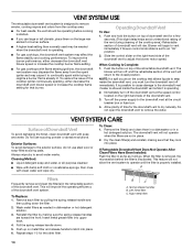
...Remove the filter(s) and clean them on top of downdraft vent will rise. If Retractable Downdraft Vent Does Not Operate After Clean Filters Have Been Installed: Push the filter in as far as needed when the downdraft vent is operating. ■ For gas cooktops, the downdraft vent system may ... already lit. When Cooking Is Complete: 1. NOTE: If a spill occurs on metal filter and release handle to operate until the filter is properly installed. Dry the clean filter(s) and reinstall, making sure the spring release handles are not in place. 2. This feature will not allow the vent system...
...Remove the filter(s) and clean them on top of downdraft vent will rise. If Retractable Downdraft Vent Does Not Operate After Clean Filters Have Been Installed: Push the filter in as far as needed when the downdraft vent is operating. ■ For gas cooktops, the downdraft vent system may ... already lit. When Cooking Is Complete: 1. NOTE: If a spill occurs on metal filter and release handle to operate until the filter is properly installed. Dry the clean filter(s) and reinstall, making sure the spring release handles are not in place. 2. This feature will not allow the vent system...
Installation Guide
Page 16
...specifications on our full line of your nearest designated service center. In Canada Call the Whirlpool Canada LP Customer eXperience Centre toll free: 1-800-807-6777. For model series UXD8630DY... trim Order Part Number W10387678 (black) Order Part Number W10388421 (white) For model series UXD8636DY 36" (91.4 cm) one-piece top trim Order Part Number W10387679 (black) Order ..., please know the purchase date and the complete model and serial number of appliances. ■ Installation information. ■ Use and maintenance procedures. ■ Accessory and repair parts sales. ■...
...specifications on our full line of your nearest designated service center. In Canada Call the Whirlpool Canada LP Customer eXperience Centre toll free: 1-800-807-6777. For model series UXD8630DY... trim Order Part Number W10387678 (black) Order Part Number W10388421 (white) For model series UXD8636DY 36" (91.4 cm) one-piece top trim Order Part Number W10387679 (black) Order ..., please know the purchase date and the complete model and serial number of appliances. ■ Installation information. ■ Use and maintenance procedures. ■ Accessory and repair parts sales. ■...
Installation Guide
Page 17
...the removal from accident, alteration, misuse, abuse, fire, flood, acts of God, improper installation, installation not in accordance with the product, Whirlpool Corporation or Whirlpool Canada LP (hereafter "Whirlpool") will need it. The removal and reinstallation of repair or replacement under this major appliance ... 50 United States and Canada, contact your authorized Whirlpool dealer to know your major appliance if it is installed in an inaccessible location or is not installed in which it is reported to Whirlpool within 30 days from unauthorized modifications made to published...
...the removal from accident, alteration, misuse, abuse, fire, flood, acts of God, improper installation, installation not in accordance with the product, Whirlpool Corporation or Whirlpool Canada LP (hereafter "Whirlpool") will need it. The removal and reinstallation of repair or replacement under this major appliance ... 50 United States and Canada, contact your authorized Whirlpool dealer to know your major appliance if it is installed in an inaccessible location or is not installed in which it is reported to Whirlpool within 30 days from unauthorized modifications made to published...
Dimension Guide
Page 1
... 30" (76.2 cm) and 36" (91.4 cm) Retractable (Pop-Up) Downdraft Vent System PRODUCT MODEL NUMBERS PRODUCT DIMENSIONS UXD8630DY UXD8636DY Electrical A 120 Volt, 60 Hz., AC only 15-amp fused, electrical circuit is required. Check for the minimum distance between the ... Sites, Communities and Setups) ANSI A225.1/NFPA 501A*, or latest edition, or with installation clearances specified on the front of 3 Because Whirlpool Corporation policy includes a continuous commitment to your specific installation. q All openings in a cabinet with a bull-nosed front edge are for cooktop...
... 30" (76.2 cm) and 36" (91.4 cm) Retractable (Pop-Up) Downdraft Vent System PRODUCT MODEL NUMBERS PRODUCT DIMENSIONS UXD8630DY UXD8636DY Electrical A 120 Volt, 60 Hz., AC only 15-amp fused, electrical circuit is required. Check for the minimum distance between the ... Sites, Communities and Setups) ANSI A225.1/NFPA 501A*, or latest edition, or with installation clearances specified on the front of 3 Because Whirlpool Corporation policy includes a continuous commitment to your specific installation. q All openings in a cabinet with a bull-nosed front edge are for cooktop...
Dimension Guide
Page 2
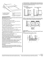
... all joints in your application. q Venting system must be directed down through either interior-mounted or exterior-mounted blower installations, the vent system length should not exceed the maximum lengths listed in the Maximum Length of elbows should be mounted ...improve Dimensions are for your area. Front (Standard) Mounted Blower Motor B A D M C E F G L H K J I Because Whirlpool Corporation policy includes a continuous commitment to be constructed. W10342491C 2/8/2012 q Use clamps or duct tape to change materials and specifications without notice. If...
... all joints in your application. q Venting system must be directed down through either interior-mounted or exterior-mounted blower installations, the vent system length should not exceed the maximum lengths listed in the Maximum Length of elbows should be mounted ...improve Dimensions are for your area. Front (Standard) Mounted Blower Motor B A D M C E F G L H K J I Because Whirlpool Corporation policy includes a continuous commitment to be constructed. W10342491C 2/8/2012 q Use clamps or duct tape to change materials and specifications without notice. If...

Dimension Guide
Page 3
... = 8.0 ft (2.4 m) Transition = 4.5 ft (1.4 cm) Length of 35 ft (8.9 m). 2 - 90° elbow = 10.0 ft (3 m) 1 - For complete details, see Installation our products, we reserve the right to change materials and specifications without notice. Wall cap B. 6" (15.2 cm) round metal vent C. 16" (40.6 cm) maximum D. 6" (15...15.2 cm) or 3¹⁄₄" x 10" (8.3 cm x 25.4 cm) system = 22.5 ft (6.8 m) Because Whirlpool Corporation policy includes a continuous commitment to improve Dimensions are for each vent piece used in the system. Specifications subject to change without ...
... = 8.0 ft (2.4 m) Transition = 4.5 ft (1.4 cm) Length of 35 ft (8.9 m). 2 - 90° elbow = 10.0 ft (3 m) 1 - For complete details, see Installation our products, we reserve the right to change materials and specifications without notice. Wall cap B. 6" (15.2 cm) round metal vent C. 16" (40.6 cm) maximum D. 6" (15...15.2 cm) or 3¹⁄₄" x 10" (8.3 cm x 25.4 cm) system = 22.5 ft (6.8 m) Because Whirlpool Corporation policy includes a continuous commitment to improve Dimensions are for each vent piece used in the system. Specifications subject to change without ...
