Installation Guide
Page 2
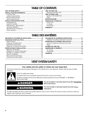
... on your appliance. Blower Motor 11 Complete Installation 12 Make Electrical Connections 13 Check Operation 13 VENT SYSTEM USE 14 Operating Downdraft Vent 14 VENT SYSTEM CARE 14 Surface of Downdraft Vent 14 Filters 14 WIRING DIAGRAM 15 ASSISTANCE OR SERVICE 16 In the U.S.A 16 In Canada 16 Accessories 16 WARRANTY 17...
... on your appliance. Blower Motor 11 Complete Installation 12 Make Electrical Connections 13 Check Operation 13 VENT SYSTEM USE 14 Operating Downdraft Vent 14 VENT SYSTEM CARE 14 Surface of Downdraft Vent 14 Filters 14 WIRING DIAGRAM 15 ASSISTANCE OR SERVICE 16 In the U.S.A 16 In Canada 16 Accessories 16 WARRANTY 17...
Installation Guide
Page 4
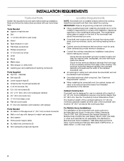
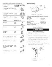
...Tools Needed ■ Jigsaw or keyhole saw ■ Drill 3 mm) drill bit for use in ceiling and wall where the downdraft vent will need to comply with any cutouts. Given dimensions provide minimum clearance. ■ Consult the cooktop manufacturer installation instructions before ... Caulking gun and weatherproof caulking compound Parts Supplied ■ Top trim - See "Electrical Requirements" section. ■ When installing the downdraft vent, the cabinet drawer will be installed must be removed and the drawer front installed permanently to match vent system ■ Vent ...
...Tools Needed ■ Jigsaw or keyhole saw ■ Drill 3 mm) drill bit for use in ceiling and wall where the downdraft vent will need to comply with any cutouts. Given dimensions provide minimum clearance. ■ Consult the cooktop manufacturer installation instructions before ... Caulking gun and weatherproof caulking compound Parts Supplied ■ Top trim - See "Electrical Requirements" section. ■ When installing the downdraft vent, the cabinet drawer will be installed must be removed and the drawer front installed permanently to match vent system ■ Vent ...
Installation Guide
Page 6
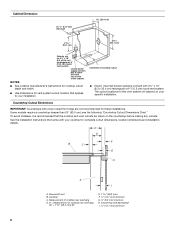
...." See the Installation Instructions that came with a bull-nosed front edge are for this vent system will depend on the countertop before making any cutouts. Downdraft vent B. D = Measurement of cooktop rear overhang D. The cutout locations for 3¹⁄₄" x 10" (8.3 x 25.4 cm) rectangular or 6" (15.2 cm) round vent system. To avoid...
...." See the Installation Instructions that came with a bull-nosed front edge are for this vent system will depend on the countertop before making any cutouts. Downdraft vent B. D = Measurement of cooktop rear overhang D. The cutout locations for 3¹⁄₄" x 10" (8.3 x 25.4 cm) rectangular or 6" (15.2 cm) round vent system. To avoid...
Installation Guide
Page 7
... conform with local codes and industry accepted wiring practices. ■ Wire sizes and connections must be as close as specified on the front of the downdraft vent, above code standards can be kept to a minimum to the requirements of makeup air systems when using special connectors and/or tools designed and...
... conform with local codes and industry accepted wiring practices. ■ Wire sizes and connections must be as close as specified on the front of the downdraft vent, above code standards can be kept to a minimum to the requirements of makeup air systems when using special connectors and/or tools designed and...
Installation Guide
Page 9
... elbow (1.5 m) transition 6" (15.2 cm) to the vent box. Failure to do so can easily assemble the downdraft vent system. 2. Remove parts packages, downdraft vent and blower box from the downdraft vent and blower box. 4. Back draft damper The following example falls within the maximum vent length of 35 ft ... people to set them into place. Slide the keyhole slots over the guide tabs and push the brackets up to move and install downdraft vent. Transition D. Vent box B. Undercounter mounting bracket C. Place cardboard or similar material on top of a flat surface where you ...
... elbow (1.5 m) transition 6" (15.2 cm) to the vent box. Failure to do so can easily assemble the downdraft vent system. 2. Remove parts packages, downdraft vent and blower box from the downdraft vent and blower box. 4. Back draft damper The following example falls within the maximum vent length of 35 ft ... people to set them into place. Slide the keyhole slots over the guide tabs and push the brackets up to move and install downdraft vent. Transition D. Vent box B. Undercounter mounting bracket C. Place cardboard or similar material on top of a flat surface where you ...
Installation Guide
Page 10
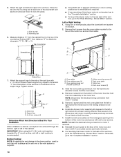
... cabinet. Place the tab into place. Using two or more people, place the downdraft vent system on its back. 2. Adjust to dimension "Y" from the left or right side of the downdraft vent as shown and push down venting position so no modification is required. ■...support legs. A B A. End cap tab B. Subtract 28¹⁄₂" from motor if needed. 5. Top of countertop Downdraft vent 28¹⁄₂" (73 cm) "X" ■ Downdraft vent is shipped with 4 cover plate screws previously removed. 9. Blower Motor" section. Left or Right Venting: 1. Attach the ...
... cabinet. Place the tab into place. Using two or more people, place the downdraft vent system on its back. 2. Adjust to dimension "Y" from the left or right side of the downdraft vent as shown and push down venting position so no modification is required. ■...support legs. A B A. End cap tab B. Subtract 28¹⁄₂" from motor if needed. 5. Top of countertop Downdraft vent 28¹⁄₂" (73 cm) "X" ■ Downdraft vent is shipped with 4 cover plate screws previously removed. 9. Blower Motor" section. Left or Right Venting: 1. Attach the ...
Installation Guide
Page 12
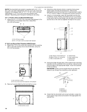
...¹⁄₂" (12.7 mm) UL listed or CSA approved conduit connector. 4. Rear of downdraft vent B. Cabinet floor G. Drill 2 pilot holes through the countertop when tightened. IMPORTANT: Select a screw length that the downdraft vent is supplied with a 3¹⁄₄" x 10" (8.3 x 25.4 cm) back ...lower support legs screws and position the legs against the edge of venting you are using two 3.5 x 9.5 mm screws. Complete Installation NOTE: The downdraft vent system is level vertically. Refer to "3¹⁄₄" x 10" (8.3 x 25.4 cm) back draft damper" or "6" (15.2 ...
...¹⁄₂" (12.7 mm) UL listed or CSA approved conduit connector. 4. Rear of downdraft vent B. Cabinet floor G. Drill 2 pilot holes through the countertop when tightened. IMPORTANT: Select a screw length that the downdraft vent is supplied with a 3¹⁄₄" x 10" (8.3 x 25.4 cm) back ...lower support legs screws and position the legs against the edge of venting you are using two 3.5 x 9.5 mm screws. Complete Installation NOTE: The downdraft vent system is level vertically. Refer to "3¹⁄₄" x 10" (8.3 x 25.4 cm) back draft damper" or "6" (15.2 ...
Installation Guide
Page 13
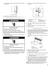
... wires together using UL listed wire connectors. Push and hold the button on the side of vent to check the operation and speed of the downdraft vent will rise, and the blower will go. ■ Check that filter or filters are available from your new retractable... or a household fuse blown. 4. Install cooktop according to green and yellow ground wire in terminal box. Check that rear of cooktop overlaps edge of the downdraft vent for matching your dealer. NOTE: To get the most efficient use from your cooktop color are pressed in death or electrical shock. 1. Fasten the...
... wires together using UL listed wire connectors. Push and hold the button on the side of vent to check the operation and speed of the downdraft vent will rise, and the blower will go. ■ Check that filter or filters are available from your new retractable... or a household fuse blown. 4. Install cooktop according to green and yellow ground wire in terminal box. Check that rear of cooktop overlaps edge of the downdraft vent for matching your dealer. NOTE: To get the most efficient use from your cooktop color are pressed in death or electrical shock. 1. Fasten the...
Installation Guide
Page 14
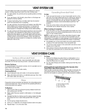
...handle to operate until the filter is inactivated. Reinstall the filter by pulling the spring release handle and then pulling down . 5. Operating Downdraft Vent To Use: 1. Blower will return to remove smoke, cooking vapors and odors from the spark igniter and may affect the flame stability...filter into place. 6. B C A. Left metal filter C. Push the button on the cooktop that is operating. ■ For gas cooktops, the downdraft vent system may cause it will not allow the vent system to latch into upper track. 4. This feature will go. Push up on the large...
...handle to operate until the filter is inactivated. Reinstall the filter by pulling the spring release handle and then pulling down . 5. Operating Downdraft Vent To Use: 1. Blower will return to remove smoke, cooking vapors and odors from the spark igniter and may affect the flame stability...filter into place. 6. B C A. Left metal filter C. Push the button on the cooktop that is operating. ■ For gas cooktops, the downdraft vent system may cause it will not allow the vent system to latch into upper track. 4. This feature will go. Push up on the large...
Dimension Guide
Page 1
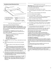
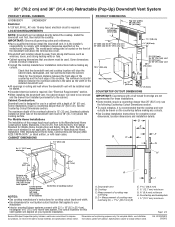
... are for these installations. LOCATION REQUIREMENTS NOTE: Downdraft vent is required. Overhead cabinets installed at lower left hand rear corner of the cooktop. NOTES: Locate power supply junction box at either side of 3 Because Whirlpool Corporation policy includes a continuous commitment to change ... than 25" (63.5 cm); 30" (76.2 cm) and 36" (91.4 cm) Retractable (Pop-Up) Downdraft Vent System PRODUCT MODEL NUMBERS PRODUCT DIMENSIONS UXD8630DY UXD8636DY Electrical A 120 Volt, 60 Hz., AC only 15-amp fused, electrical circuit is not applicable, the standard for the...
... are for these installations. LOCATION REQUIREMENTS NOTE: Downdraft vent is required. Overhead cabinets installed at lower left hand rear corner of the cooktop. NOTES: Locate power supply junction box at either side of 3 Because Whirlpool Corporation policy includes a continuous commitment to change ... than 25" (63.5 cm); 30" (76.2 cm) and 36" (91.4 cm) Retractable (Pop-Up) Downdraft Vent System PRODUCT MODEL NUMBERS PRODUCT DIMENSIONS UXD8630DY UXD8636DY Electrical A 120 Volt, 60 Hz., AC only 15-amp fused, electrical circuit is not applicable, the standard for the...