Warranty Information
Page 1
..., to replace or repair house fuses, or to repair or replace appliance light bulbs, air filters or water filters. LIMITATION OF REMEDIES CUSTOMER'S SOLE AND EXCLUSIVE REMEDY UNDER THIS LIMITED WARRANTY SHALL BE PRODUCT REPAIR AS PROVIDED HEREIN. If you may find this warranty. 8. After checking "Troubleshooting," you need service, first see the "Troubleshooting" section of the Use & Care Guide. Service calls to correct the installation of your major appliance. Costs associated with original model/serial numbers that...
..., to replace or repair house fuses, or to repair or replace appliance light bulbs, air filters or water filters. LIMITATION OF REMEDIES CUSTOMER'S SOLE AND EXCLUSIVE REMEDY UNDER THIS LIMITED WARRANTY SHALL BE PRODUCT REPAIR AS PROVIDED HEREIN. If you may find this warranty. 8. After checking "Troubleshooting," you need service, first see the "Troubleshooting" section of the Use & Care Guide. Service calls to correct the installation of your major appliance. Costs associated with original model/serial numbers that...
Installation Guide
Page 2
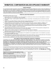
...VENT SYSTEM SAFETY 2 INSTALLATION REQUIREMENTS 4 Tools and Parts 4 Location Requirements 4 Electrical Requirements 7 Venting Requirements 7 INSTALLATION INSTRUCTIONS 8 Venting Methods 8 Install Vent System 9 Rear Mounting - This symbol alerts you to reduce the chance of others . Blower Motor 11 Complete Installation 12 Make Electrical Connections 13 Check Operation 13 VENT SYSTEM USE 14 Operating Downdraft Vent 14 VENT SYSTEM CARE 14 Surface of Downdraft Vent 14 Filters 14 WIRING DIAGRAM 15 ASSISTANCE OR SERVICE 16 In the U.S.A 16 In Canada 16 Accessories 16 WARRANTY...
...VENT SYSTEM SAFETY 2 INSTALLATION REQUIREMENTS 4 Tools and Parts 4 Location Requirements 4 Electrical Requirements 7 Venting Requirements 7 INSTALLATION INSTRUCTIONS 8 Venting Methods 8 Install Vent System 9 Rear Mounting - This symbol alerts you to reduce the chance of others . Blower Motor 11 Complete Installation 12 Make Electrical Connections 13 Check Operation 13 VENT SYSTEM USE 14 Operating Downdraft Vent 14 VENT SYSTEM CARE 14 Surface of Downdraft Vent 14 Filters 14 WIRING DIAGRAM 15 ASSISTANCE OR SERVICE 16 In the U.S.A 16 In Canada 16 Accessories 16 WARRANTY...
Installation Guide
Page 3
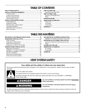
... needed for proper combustion and exhausting of gases through the flue (chimney) of the surface element. You can fight the fire with your back to duct air outside - Heat oils slowly on "Kitchen Fire Safety Tips" published by the manufacturer. aBased on low or medium settings. ■ Always turn off at service panel and lock the service disconnecting means to the service panel. ■ Installation work and electrical wiring...
... needed for proper combustion and exhausting of gases through the flue (chimney) of the surface element. You can fight the fire with your back to duct air outside - Heat oils slowly on "Kitchen Fire Safety Tips" published by the manufacturer. aBased on low or medium settings. ■ Always turn off at service panel and lock the service disconnecting means to the service panel. ■ Installation work and electrical wiring...
Installation Guide
Page 4
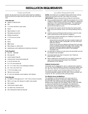
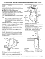
...) motor box ■ ¼" (6.4 mm) deep cover ■ Flat vent cover plate ■ 6" (15.2 cm) diameter vent transition with damper Parts Needed ■ UL listed or CSA approved ½" (12.7 mm) conduit connector ■ Wall or roof cap with damper to comply with local codes. 4 It is the installer's responsibility to match vent system ■ Vent system ■ Home power supply cable ■ UL listed wire connectors (3) ■ Vent clamps/duct tape as required Location Requirements NOTE: Downdraft vent is designed for Manufactured Home Installation...
...) motor box ■ ¼" (6.4 mm) deep cover ■ Flat vent cover plate ■ 6" (15.2 cm) diameter vent transition with damper Parts Needed ■ UL listed or CSA approved ½" (12.7 mm) conduit connector ■ Wall or roof cap with damper to comply with local codes. 4 It is the installer's responsibility to match vent system ■ Vent system ■ Home power supply cable ■ UL listed wire connectors (3) ■ Vent clamps/duct tape as required Location Requirements NOTE: Downdraft vent is designed for Manufactured Home Installation...

Installation Guide
Page 5
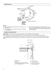
...Dimensions 13¹⁄₂" (34.3 cm) retractable vent height Top trim widths: 30" (76.2 cm) 36" (91.4 cm) 27" (68.6 cm) for 30" (76.2 cm) vent 33" (83.8 cm) for 36" (91.4 cm) vent 1¹⁄₂" (3.8 cm 0.95 cm) 13¹⁄₈" (33.4 cm) 16¹⁄₂" (42.0 cm) As-Received Blower... (76.2 cm) vent 8¹⁄₄"(21.0 cm) for 36" (91.4 cm) vent 28¹⁄₂" (72.4 cm) ³⁄₄ (1.9 cm) 10" (25.4 cm) 2¹⁄₈" (5.4 cm) Reversed Blower Front of Range Hood 10" (25.4 cm) Front of Range Hood 4³⁄₄" ...
...Dimensions 13¹⁄₂" (34.3 cm) retractable vent height Top trim widths: 30" (76.2 cm) 36" (91.4 cm) 27" (68.6 cm) for 30" (76.2 cm) vent 33" (83.8 cm) for 36" (91.4 cm) vent 1¹⁄₂" (3.8 cm 0.95 cm) 13¹⁄₈" (33.4 cm) 16¹⁄₂" (42.0 cm) As-Received Blower... (76.2 cm) vent 8¹⁄₄"(21.0 cm) for 36" (91.4 cm) vent 28¹⁄₂" (72.4 cm) ³⁄₄ (1.9 cm) 10" (25.4 cm) 2¹⁄₈" (5.4 cm) Reversed Blower Front of Range Hood 10" (25.4 cm) Front of Range Hood 4³⁄₄" ...
Installation Guide
Page 6
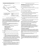
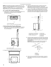
...) round vent system. Some models require a countertop deeper than 25" (63.5 cm); Cooktop C. Measurement of cooktop rear overhang (C) + 1 46.2 mm] (E) E. 1 46.2 mm) F. ½" (12.7 mm) minimum G. ¼" (6.4 mm) minimum H. Countertop Cutout Dimensions IMPORTANT: Countertops with a bull-nosed front edge are for these installations. see the following "Countertop Cutout Dimensions Chart." Downdraft vent B. Locate power supply junction box at lower left hand rear corner of cooktop cutout ■ Interior mounted blower systems connect with...
...) round vent system. Some models require a countertop deeper than 25" (63.5 cm); Cooktop C. Measurement of cooktop rear overhang (C) + 1 46.2 mm] (E) E. 1 46.2 mm) F. ½" (12.7 mm) minimum G. ¼" (6.4 mm) minimum H. Countertop Cutout Dimensions IMPORTANT: Countertops with a bull-nosed front edge are for these installations. see the following "Countertop Cutout Dimensions Chart." Downdraft vent B. Locate power supply junction box at lower left hand rear corner of cooktop cutout ■ Interior mounted blower systems connect with...
Installation Guide
Page 7
...) on the model/serial rating plate. Flexible elbows count twice as much as 2 ft (0.6 m) of Vent System chart. Recommended vent system length: For either interior-mounted or exterior-mounted blower installations, the vent system length should not exceed the maximum lengths listed in the Installation Instructions. The damper should be on the front of copper wire using ventilation systems greater than one elbow is used . ■ Use clamps or duct tape to seal all local codes and ordinances. The...
...) on the model/serial rating plate. Flexible elbows count twice as much as 2 ft (0.6 m) of Vent System chart. Recommended vent system length: For either interior-mounted or exterior-mounted blower installations, the vent system length should not exceed the maximum lengths listed in the Installation Instructions. The damper should be on the front of copper wire using ventilation systems greater than one elbow is used . ■ Use clamps or duct tape to seal all local codes and ordinances. The...

Installation Guide
Page 8
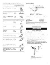
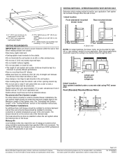
... pipe. Maximum Length of Vent System Vent Length 6" (15.2 cm) round 35 ft (8.9 m) 3¹⁄₄" x 10" (8.3 cm x 25.4 cm) 35 ft (8.9 m) 8 INSTALLATION INSTRUCTIONS Venting Methods Determine which venting method is required from the blower motor box. Most island applications would still require the venting to 6" (15.2 cm) round vent if needed for your application. Built-In Cabinet Locations Rear Mounted Blower Motor B A D M C L E F G H A B A. K. 6" (15.2 cm) round 90° PVC sewer pipe elbow L. 6" (15.2 cm) round PVC coupling M. 12...
... pipe. Maximum Length of Vent System Vent Length 6" (15.2 cm) round 35 ft (8.9 m) 3¹⁄₄" x 10" (8.3 cm x 25.4 cm) 35 ft (8.9 m) 8 INSTALLATION INSTRUCTIONS Venting Methods Determine which venting method is required from the blower motor box. Most island applications would still require the venting to 6" (15.2 cm) round vent if needed for your application. Built-In Cabinet Locations Rear Mounted Blower Motor B A D M C L E F G H A B A. K. 6" (15.2 cm) round 90° PVC sewer pipe elbow L. 6" (15.2 cm) round PVC coupling M. 12...
Installation Guide
Page 9
Blower motor C. 90° elbows B. wall cap = 0.0 ft (0.0 m) 8 ft (2.4 m) straight = 8.0 ft (2.4 m) Transition = 4.5 ft (1.4 cm) Length of 35 ft (8.9 m). 2 - 90° elbow = 10.0 ft (3 m) 1 - Remove all shipping materials, tape and film from the carton. 3. B A C D A. Back draft damper The following example falls within the maximum vent length of 6" (15.2 cm) or 3¹⁄₄" x 10" = 22.5 ft (6.8 m) (8.3 cm x 25.4 cm) system Install Vent System WARNING Excessive Weight Hazard Use two or...
Blower motor C. 90° elbows B. wall cap = 0.0 ft (0.0 m) 8 ft (2.4 m) straight = 8.0 ft (2.4 m) Transition = 4.5 ft (1.4 cm) Length of 35 ft (8.9 m). 2 - 90° elbow = 10.0 ft (3 m) 1 - Remove all shipping materials, tape and film from the carton. 3. B A C D A. Back draft damper The following example falls within the maximum vent length of 6" (15.2 cm) or 3¹⁄₄" x 10" = 22.5 ft (6.8 m) (8.3 cm x 25.4 cm) system Install Vent System WARNING Excessive Weight Hazard Use two or...
Installation Guide
Page 10
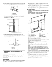
... the electrical wiring connection from the bottom of the vent box to lock into the mounting slot at the exit end of the motor box and secure with a damper at each support leg. Support leg C. 4 x 8 mm screws (4) Determine Which Vent Direction Is Best For Your Installation When installed in the down position, a wall or roof cap with vent cover screws. IMPORTANT: When using the 6" (15.2 cm) vent transition (supplied) for the venting direction to dimension "Y" from motor if needed. 5. End cap tab...
... the electrical wiring connection from the bottom of the vent box to lock into the mounting slot at the exit end of the motor box and secure with a damper at each support leg. Support leg C. 4 x 8 mm screws (4) Determine Which Vent Direction Is Best For Your Installation When installed in the down position, a wall or roof cap with vent cover screws. IMPORTANT: When using the 6" (15.2 cm) vent transition (supplied) for the venting direction to dimension "Y" from motor if needed. 5. End cap tab...

Installation Guide
Page 11
... island cabinet locations. Front View A A A B C A. Wire mounting plate C. Blower motor box 2. Remove 6 screws from the mounting flanges of the blower motor box. Lift the ¼" (6.4 mm) deep cover off the shoulder screws in the keyhole slots and set blower motor box aside. 3. Grommet 7. Slide the wire assembly through the opening to the "Complete Installation" section. 11 Mount the blower motor box to remove it. 8. Go to the opposite side of the vent box and reconnect the wire connection to vent box using the 4 screws previously removed. 11. Screws B. Rear View...
... island cabinet locations. Front View A A A B C A. Wire mounting plate C. Blower motor box 2. Remove 6 screws from the mounting flanges of the blower motor box. Lift the ¼" (6.4 mm) deep cover off the shoulder screws in the keyhole slots and set blower motor box aside. 3. Grommet 7. Slide the wire assembly through the opening to the "Complete Installation" section. 11 Mount the blower motor box to remove it. 8. Go to the opposite side of the vent box and reconnect the wire connection to vent box using the 4 screws previously removed. 11. Screws B. Rear View...
Installation Guide
Page 12
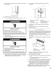
... terminal box. Terminal box cover 12 Remove the appropriate knockout from the front or rear panel and install a ¹⁄₂" (12.7 mm) UL listed or CSA approved conduit connector. 4. Edge of downdraft vent B. Rear of the appropriate length, mount the brackets to the vent opening (left or right side venting only is centered in the blower motor box, using two 3.5 x 9.5 mm screws. Cabinet floor G. Determine which direction (front or rear) the home power supply cable will...
... terminal box. Terminal box cover 12 Remove the appropriate knockout from the front or rear panel and install a ¹⁄₂" (12.7 mm) UL listed or CSA approved conduit connector. 4. Edge of downdraft vent B. Rear of the appropriate length, mount the brackets to the vent opening (left or right side venting only is centered in the blower motor box, using two 3.5 x 9.5 mm screws. Cabinet floor G. Determine which direction (front or rear) the home power supply cable will...
Installation Guide
Page 13
... the lower support legs screws. Black wires E. Downdraft vent wiring 5. Check Operation 1. Filters 2. FC D E A B A. For information on the conduit connector. Connect the 2 white wires together using UL listed wire connectors. The retractable section of retractable downdraft vent by ³⁄₈" (9.5 mm). Connect the green (or green/yellow) ground wire to seal all parts and panels before servicing. Disconnect power. 2. Slide the control slider on the top of the blower. 3. UL listed or CSA approved conduit connector F. Install cooktop according...
... the lower support legs screws. Black wires E. Downdraft vent wiring 5. Check Operation 1. Filters 2. FC D E A B A. For information on the conduit connector. Connect the 2 white wires together using UL listed wire connectors. The retractable section of retractable downdraft vent by ³⁄₈" (9.5 mm). Connect the green (or green/yellow) ground wire to seal all parts and panels before servicing. Disconnect power. 2. Slide the control slider on the top of the blower. 3. UL listed or CSA approved conduit connector F. Install cooktop according...
Installation Guide
Page 14
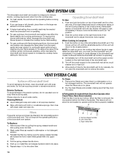
... decrease the downdraft vent blower speed or increase the cooktop burner flame setting. ■ For gas cooktops with flame sensing ignitions, the downdraft vent system may be operating before cooking is started. ■ If you must turn the downdraft vent off the downdraft vent at the circuit breaker box or fuse box. 4. If Retractable Downdraft Vent Does Not Operate After Clean Filters Have Been Installed: Push the filter in dishwasher or hot detergent solution. 3. Remove each filter by making sure that is...
... decrease the downdraft vent blower speed or increase the cooktop burner flame setting. ■ For gas cooktops with flame sensing ignitions, the downdraft vent system may be operating before cooking is started. ■ If you must turn the downdraft vent off the downdraft vent at the circuit breaker box or fuse box. 4. If Retractable Downdraft Vent Does Not Operate After Clean Filters Have Been Installed: Push the filter in dishwasher or hot detergent solution. 3. Remove each filter by making sure that is...

Installation Guide
Page 15
... N.O. N.O. Blower Switch Operation Contact Function 1 - 3 OFF 3 - 5 1st Speed 5 - 7 2nd Speed 8 - 10 3rd Speed 10 - 12 4th Speed Component Layout Num. Com N.C. 1 BR 1 GY R BK BK GY GY R R W W BR BR R GY BR GY GY BR GY N.O. Com 3 N.C. plenum up limit switch 5 Motor microswitch 6 Plenum drive motor 7 Blower motor 8 Blower speed switches 9 Start sw. - WIRING DIAGRAM Y 7 BR Y/G S50 9 Neutral 4˚ Speed 3˚ Speed 2˚ Speed 1˚ Speed Motor Specifications Power supply Frequency 120 VAC 60 Hz Wattage rating...
... N.O. N.O. Blower Switch Operation Contact Function 1 - 3 OFF 3 - 5 1st Speed 5 - 7 2nd Speed 8 - 10 3rd Speed 10 - 12 4th Speed Component Layout Num. Com N.C. 1 BR 1 GY R BK BK GY GY R R W W BR BR R GY BR GY GY BR GY N.O. Com 3 N.C. plenum up limit switch 5 Motor microswitch 6 Plenum drive motor 7 Blower motor 8 Blower speed switches 9 Start sw. - WIRING DIAGRAM Y 7 BR Y/G S50 9 Neutral 4˚ Speed 3˚ Speed 2˚ Speed 1˚ Speed Motor Specifications Power supply Frequency 120 VAC 60 Hz Wattage rating...
Installation Guide
Page 16
.... Accessories NOTE: Instructions are trained to fulfill the product warranty and provide after-warranty service, anywhere in your nearest designated service center. Whirlpool Canada LP designated service technicians are made with each kit. ASSISTANCE OR SERVICE When calling for assistance or service, please know the purchase date and the complete model and serial number of appliances. ■ Installation information. ■ Use and maintenance procedures. ■ Accessory and repair parts sales. ■ Specialized customer...
.... Accessories NOTE: Instructions are trained to fulfill the product warranty and provide after-warranty service, anywhere in your nearest designated service center. Whirlpool Canada LP designated service technicians are made with each kit. ASSISTANCE OR SERVICE When calling for assistance or service, please know the purchase date and the complete model and serial number of appliances. ■ Installation information. ■ Use and maintenance procedures. ■ Accessory and repair parts sales. ■ Specialized customer...
Installation Guide
Page 17
... removed, altered or cannot be repaired in the home and only in accordance with electrical or plumbing codes, or use your major appliance, to replace or repair house fuses, or to correct house wiring or plumbing. 2. Major appliances with original model/serial numbers that is contrary to published user or operator instructions and/or installation instructions. 4. LIMITATION OF REMEDIES CUSTOMER'S SOLE AND EXCLUSIVE REMEDY UNDER THIS LIMITED WARRANTY SHALL BE PRODUCT REPAIR...
... removed, altered or cannot be repaired in the home and only in accordance with electrical or plumbing codes, or use your major appliance, to replace or repair house fuses, or to correct house wiring or plumbing. 2. Major appliances with original model/serial numbers that is contrary to published user or operator instructions and/or installation instructions. 4. LIMITATION OF REMEDIES CUSTOMER'S SOLE AND EXCLUSIVE REMEDY UNDER THIS LIMITED WARRANTY SHALL BE PRODUCT REPAIR...
Dimension Guide
Page 1
... the terminal box cover. q Consult the cooktop manufacturer installation instructions before making any cutouts. q To avoid mistakes, it is the same as windows, doors, and strong heating vents or fans. Downdraft vent B. Measurement of the cooktop. Ref. Check for use in ceiling and wall where the downdraft vent will need to your specific installation. q When installing the downdraft vent, the cabinet drawer will be installed must be drawn on the model/serial rating plate. Cabinet Construction: Downdraft vent is designed for the minimum...
... the terminal box cover. q Consult the cooktop manufacturer installation instructions before making any cutouts. q To avoid mistakes, it is the same as windows, doors, and strong heating vents or fans. Downdraft vent B. Measurement of the cooktop. Ref. Check for use in ceiling and wall where the downdraft vent will need to your specific installation. q When installing the downdraft vent, the cabinet drawer will be installed must be drawn on the model/serial rating plate. Cabinet Construction: Downdraft vent is designed for the minimum...
Dimension Guide
Page 2
.... Most island applications would still require the venting to be directed down through either interior-mounted or exterior-mounted blower installations, the vent system length should be as close as 2 ft (0.6 m) of the vent system. Front (Standard) Mounted Blower Motor B A D M C E F G L H K J I Because Whirlpool Corporation policy includes a continuous commitment to change materials and specifications without notice. The specified CFM varies from locale to backsplash or rear wall B 19.1 mm) maximum backsplash depth VENTING REQUIREMENTS C. 27...
.... Most island applications would still require the venting to be directed down through either interior-mounted or exterior-mounted blower installations, the vent system length should be as close as 2 ft (0.6 m) of the vent system. Front (Standard) Mounted Blower Motor B A D M C E F G L H K J I Because Whirlpool Corporation policy includes a continuous commitment to change materials and specifications without notice. The specified CFM varies from locale to backsplash or rear wall B 19.1 mm) maximum backsplash depth VENTING REQUIREMENTS C. 27...

Dimension Guide
Page 3
... Whirlpool Corporation policy includes a continuous commitment to improve Dimensions are for each vent piece used in the system. Transition C. 90° elbows D. 6" back draft damper (supplied) The following example falls within the maximum vent length of 3 Ref. Rear Mounted Blower Motor B A D M C L E F G H K J I . 6" (15.2 cm) round 90° PVC sewer pipe elbow J. Wall cap B. 6" (15.2 cm) round metal vent C. 16" (40.6 cm) maximum D. 6" (15.2 cm) round PVC sewer pipe E. 6" (15.2 cm) round metal vent transition with...
... Whirlpool Corporation policy includes a continuous commitment to improve Dimensions are for each vent piece used in the system. Transition C. 90° elbows D. 6" back draft damper (supplied) The following example falls within the maximum vent length of 3 Ref. Rear Mounted Blower Motor B A D M C L E F G H K J I . 6" (15.2 cm) round 90° PVC sewer pipe elbow J. Wall cap B. 6" (15.2 cm) round metal vent C. 16" (40.6 cm) maximum D. 6" (15.2 cm) round PVC sewer pipe E. 6" (15.2 cm) round metal vent transition with...


