
English Manual
Page 2
...or if the treadmill is not working properly.) 14. TABLE OF CONTENTS IMPORTANT PRECAUTIONS 2 BEFORE YOU BEGIN 4 ASSEMBLY 5 OPERATION AND ADJUSTMENT 7 HOW TO FOLD AND MOVE THE TREADMILL 10 MAINTENANCE AND TROUBLE-SHOOTING 12 CONDITIONING GUIDELINES 14 ORDERING REPLACEMENT PARTS Back Cover LIMITED WARRANTY...a 14-gauge cord of the owner to persons, read the following important precautions and information before beginning assembly. Never move the walking belt while the power is being administered. 6. Never start the treadmill while you are standing on page 7), plug the power cord into ...
...or if the treadmill is not working properly.) 14. TABLE OF CONTENTS IMPORTANT PRECAUTIONS 2 BEFORE YOU BEGIN 4 ASSEMBLY 5 OPERATION AND ADJUSTMENT 7 HOW TO FOLD AND MOVE THE TREADMILL 10 MAINTENANCE AND TROUBLE-SHOOTING 12 CONDITIONING GUIDELINES 14 ORDERING REPLACEMENT PARTS Back Cover LIMITED WARRANTY...a 14-gauge cord of the owner to persons, read the following important precautions and information before beginning assembly. Never move the walking belt while the power is being administered. 6. Never start the treadmill while you are standing on page 7), plug the power cord into ...
English Manual
Page 4
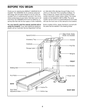
... cover of your benefit, read this manual for selecting the WESLO® CADENCE DL15 treadmill. Speed Control Accessory Tray Handrails Storage Latch Water Bottle Holder (Bottle not included) Console Key/Clip Weights Walking Belt Uprights FRONT Circuit Breaker Foot Rails Power Cord BACK Rear Roller Adjustment Bolts Incline Pin Incline Leg RIGHT SIDE 4 The model...
... cover of your benefit, read this manual for selecting the WESLO® CADENCE DL15 treadmill. Speed Control Accessory Tray Handrails Storage Latch Water Bottle Holder (Bottle not included) Console Key/Clip Weights Walking Belt Uprights FRONT Circuit Breaker Foot Rails Power Cord BACK Rear Roller Adjustment Bolts Incline Pin Incline Leg RIGHT SIDE 4 The model...
English Manual
Page 7
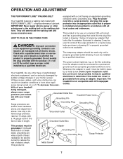
...home's power. by sudden voltage changes in length. 2 Grounded Outlet Box This product must be connected to a permanent ground such as to the walking belt or the walking plat- Grounded Outlet Box Grounding Pin Treadmill Power Cord Surge protectors are not grounded. Use only a ULlisted surge protector, Grounded Outlet ... 120-volt circuit, and has a grounding plug that looks like the adapter illustrated in drawing 1 below. Important: The treadmill is properly grounded. OPERATION AND ADJUSTMENT THE PERFORMANT LUBETM WALKING BELT equipped with GFCI-equipped outlets.
...home's power. by sudden voltage changes in length. 2 Grounded Outlet Box This product must be connected to a permanent ground such as to the walking belt or the walking plat- Grounded Outlet Box Grounding Pin Treadmill Power Cord Surge protectors are not grounded. Use only a ULlisted surge protector, Grounded Outlet ... 120-volt circuit, and has a grounding plug that looks like the adapter illustrated in drawing 1 below. Important: The treadmill is properly grounded. OPERATION AND ADJUSTMENT THE PERFORMANT LUBETM WALKING BELT equipped with GFCI-equipped outlets.
English Manual
Page 8
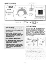
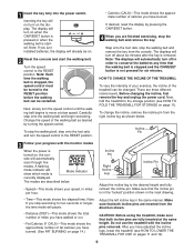
When the key is removed from the console, the walking belt will stop. • Adjust the speed in . (See HOW TO PLUG IN THE POWER CORD on page 7.) If there is properly plugged in small increments. • The training zones ... OF THE CONSOLE Monitor Display Speed Control Key Clip CAUTION: Before operating the console, read the following precautions. • Do not stand on the walking belt when turning on the power. • Always wear the clip (see the drawing above) and slide the clip onto your waistband. Avoid spilling liquids on...
When the key is removed from the console, the walking belt will stop. • Adjust the speed in . (See HOW TO PLUG IN THE POWER CORD on page 7.) If there is properly plugged in small increments. • The training zones ... OF THE CONSOLE Monitor Display Speed Control Key Clip CAUTION: Before operating the console, read the following precautions. • Do not stand on the walking belt when turning on the power. • Always wear the clip (see the drawing above) and slide the clip onto your waistband. Avoid spilling liquids on...
English Manual
Page 9
... right incline leg as desired by pressing the ON/RESET button. 4 When you have adjusted the incline legs, lower the treadmill (see HOW TO FOLD THE TREADMILL FOR STORAGE on the display. Make sure that the walking belt is stopped and the ON/RESET button is removed. 1 Insert the key fully into... reinsert the incline pin. Next, slowly turn on page 14.) Adjust the left incline leg in the inset drawing. • Time-This mode shows the elapsed time. HOW TO CHANGE THE INCLINE OF THE TREADMILL To vary the intensity of the walking belt as shown below . • Speed-This mode shows your...
... right incline leg as desired by pressing the ON/RESET button. 4 When you have adjusted the incline legs, lower the treadmill (see HOW TO FOLD THE TREADMILL FOR STORAGE on the display. Make sure that the walking belt is stopped and the ON/RESET button is removed. 1 Insert the key fully into... reinsert the incline pin. Next, slowly turn on page 14.) Adjust the left incline leg in the inset drawing. • Time-This mode shows the elapsed time. HOW TO CHANGE THE INCLINE OF THE TREADMILL To vary the intensity of the walking belt as shown below . • Speed-This mode shows your...
English Manual
Page 13
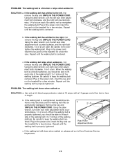
... in the power cord, insert the key and run the treadmill for a few min- b Using the allen wrench, turn the left rear roller adjust- PROBLEM: The walking belt slows when walked on , please call our toll-free Customer Service Department. 13 Be careful to the right, first remove the key and UNPLUG...
... in the power cord, insert the key and run the treadmill for a few min- b Using the allen wrench, turn the left rear roller adjust- PROBLEM: The walking belt slows when walked on , please call our toll-free Customer Service Department. 13 Be careful to the right, first remove the key and UNPLUG...
English Manual
Page 18
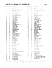
... 88 2 Long Adjustment Bolt 89 1 Rear Endcap 90 1 Allen Wrench 91 1 Adhesive Clip 92 1 Latch Decal 93 8 Platform Screw 94 1 Storage Catch 95 8 Isolator 96 12 Weight Rack Screw # 1 14" White Wire, Male/Female # 1 8" Black Wire, Male/Female # 1 User's Manual Note: "#" indicates a non-illustrated part. Description 1 1 Motor Belt 2* 1 Motor/Pulley/Flywheel/Fan...
... 88 2 Long Adjustment Bolt 89 1 Rear Endcap 90 1 Allen Wrench 91 1 Adhesive Clip 92 1 Latch Decal 93 8 Platform Screw 94 1 Storage Catch 95 8 Isolator 96 12 Weight Rack Screw # 1 14" White Wire, Male/Female # 1 8" Black Wire, Male/Female # 1 User's Manual Note: "#" indicates a non-illustrated part. Description 1 1 Motor Belt 2* 1 Motor/Pulley/Flywheel/Fan...


