

English Manual
Page 1
.... Serial Number Decal (Under Seat) QUESTIONS? MST CAUTION Read all precautions and instructions in the space above for future reference. Save this equipment. USERÕS MANUAL PATENT PENDING WESY96480 Serial No. CUSTOMER HOT LINE: 1-800-999-3756 Mon.ÐFri., 6 a.m.Ð6 p.m. TO AVOID UNNECESSARY DELAYS, PLEASE CALL DIRECT TO OUR TOLL-FREE CUSTOMER HOT LINE. Write the serial number in this manual before using...
.... Serial Number Decal (Under Seat) QUESTIONS? MST CAUTION Read all precautions and instructions in the space above for future reference. Save this equipment. USERÕS MANUAL PATENT PENDING WESY96480 Serial No. CUSTOMER HOT LINE: 1-800-999-3756 Mon.ÐFri., 6 a.m.Ð6 p.m. TO AVOID UNNECESSARY DELAYS, PLEASE CALL DIRECT TO OUR TOLL-FREE CUSTOMER HOT LINE. Write the serial number in this manual before using...
English Manual
Page 2
... you specific legal rights. ICON HEALTH & FITNESS, INC., 1500 S. 1000 W., LOGAN, UT 84321-9813 2 TABLE OF CONTENTS LIMITED WARRANTY 2 IMPORTANT PRECAUTIONS 3 BEFORE YOU BEGIN 4 ASSEMBLY 5 HOW TO USE THE HOME GYM SYSTEM 22 WEIGHT RESISTANCE CHART 24 TROUBLE-SHOOTING AND MAINTENANCE 25 CABLE DIAGRAMS 26 ORDERING REPLACEMENT PARTS Back Cover Note: A PART IDENTIFICATION CHART and a PART LIST/EXPLODED DRAWING are attached to the center of this product to be free from defects in connection with the use or...
... you specific legal rights. ICON HEALTH & FITNESS, INC., 1500 S. 1000 W., LOGAN, UT 84321-9813 2 TABLE OF CONTENTS LIMITED WARRANTY 2 IMPORTANT PRECAUTIONS 3 BEFORE YOU BEGIN 4 ASSEMBLY 5 HOW TO USE THE HOME GYM SYSTEM 22 WEIGHT RESISTANCE CHART 24 TROUBLE-SHOOTING AND MAINTENANCE 25 CABLE DIAGRAMS 26 ORDERING REPLACEMENT PARTS Back Cover Note: A PART IDENTIFICATION CHART and a PART LIST/EXPLODED DRAWING are attached to the center of this product to be free from defects in connection with the use or...
English Manual
Page 3
... leg press upright when the military press arm is being used. If you are on a foot plate when performing an exercise that the cables remain on a level surface. WARNING: Before beginning this or any worn parts immediately. 6. Inspect and tighten all precautions. 2. The weights will fall with pre-existing health problems. Read all instructions before using. It is in an commercial, rental, or institutional setting. 3. Use the home gym...
... leg press upright when the military press arm is being used. If you are on a foot plate when performing an exercise that the cables remain on a level surface. WARNING: Before beginning this or any worn parts immediately. 6. Inspect and tighten all precautions. 2. The weights will fall with pre-existing health problems. Read all instructions before using. It is in an commercial, rental, or institutional setting. 3. Use the home gym...
English Manual
Page 4
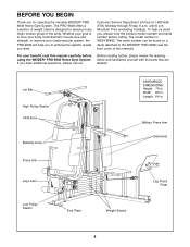
... model number and serial number before using the WEIDER¨ PRO 9648 Home Gym System. For your benefit, read this manual). Military Press Arm Backrests Press Arm Leg Lever Low Pulley Station Foot Plate Weight Stacks Leg Press Plate 4 Length: 64 in . Whether your cardiovascular system, the PRO 9648 will help us assist you to the WEIDER¨ PRO 9648 (see the front cover of the body. Customer Service Department toll-free at 1-800-9993756, Monday through Friday, 6 a.m. The PRO 9648...
... model number and serial number before using the WEIDER¨ PRO 9648 Home Gym System. For your benefit, read this manual). Military Press Arm Backrests Press Arm Leg Lever Low Pulley Station Foot Plate Weight Stacks Leg Press Plate 4 Length: 64 in . Whether your cardiovascular system, the PRO 9648 will help us assist you to the WEIDER¨ PRO 9648 (see the front cover of the body. Customer Service Department toll-free at 1-800-9993756, Monday through Friday, 6 a.m. The PRO 9648...
English Manual
Page 5
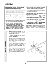
...) into five stages: 1) frame assembly, 2) press and butterfly arm assembly, 3) cable and pulley assembly, 4) seat and backrest assembly, and 5) VKR assembly. Locate and open -end or closed-end wrenches, or a set of ratchet wrenches. The hardware for each stage is packaged separately. ¥ Wait until assembly is completed. ¥ The assembly is not in a cleared area and remove the packing materials; Attach the Base (4) to see if...
...) into five stages: 1) frame assembly, 2) press and butterfly arm assembly, 3) cable and pulley assembly, 4) seat and backrest assembly, and 5) VKR assembly. Locate and open -end or closed-end wrenches, or a set of ratchet wrenches. The hardware for each stage is packaged separately. ¥ Wait until assembly is completed. ¥ The assembly is not in a cleared area and remove the packing materials; Attach the Base (4) to see if...

English Manual
Page 6
... the Leg Press Upright (56) with the #8 x 1/2Ó Self-tapping Screw (87). 2 27 87 91 74 27 3 27 High Sides of the brackets on the VKR Upright and Leg Press Upright should be on the side shown. FRAME ASSEMBLY 4 1 42 6 3 6 Slide the VKR Upright (74) and the Leg Press Upright (56) onto the indicated 5/16Ó x 2 1/2Ó Carriage Bolts (1) in the Base (4). 3 Hand-tighten a 5/16...
... the Leg Press Upright (56) with the #8 x 1/2Ó Self-tapping Screw (87). 2 27 87 91 74 27 3 27 High Sides of the brackets on the VKR Upright and Leg Press Upright should be on the side shown. FRAME ASSEMBLY 4 1 42 6 3 6 Slide the VKR Upright (74) and the Leg Press Upright (56) onto the indicated 5/16Ó x 2 1/2Ó Carriage Bolts (1) in the Base (4). 3 Hand-tighten a 5/16...

English Manual
Page 7
... Pin Grooves 19 7 Be careful not to the Front 11 Upright (42) with two 5/16Ó x 2 1/2Ó Carriage Bolts (1) and two 5/16Ó Nylon Locknuts (3). Attach the Handle (82) to the Leg Press Upright (56) with two 5/16Ó x 2 3/4Ó Bolts (11) and two 5/16Ó Nylon Locknuts (3). Attach the Top Frame (55) to tip either stack of the Rear Seat...
... Pin Grooves 19 7 Be careful not to the Front 11 Upright (42) with two 5/16Ó x 2 1/2Ó Carriage Bolts (1) and two 5/16Ó Nylon Locknuts (3). Attach the Handle (82) to the Leg Press Upright (56) with two 5/16Ó x 2 3/4Ó Bolts (11) and two 5/16Ó Nylon Locknuts (3). Attach the Top Frame (55) to tip either stack of the Rear Seat...

English Manual
Page 9
...ÑLubricate 5 27 98 17 Pulleys must be a tight fit. Attach the Leg Press Plate to pivot freely. Attach the Press Frame (17) to the Top Frame (55) with a 5/16Ó x 6Ó Bolt (60), two 1/2Ó x 3/4Ó Spacers (61), and a 5/16Ó Nylon Locknut (3). 9 61 60 73 3 61 60 3 55 62 FRAME ASSEMBLY ARM ASSEMBLY 10. Attach the upper ends of the Short Weight Guides...
...ÑLubricate 5 27 98 17 Pulleys must be a tight fit. Attach the Leg Press Plate to pivot freely. Attach the Press Frame (17) to the Top Frame (55) with a 5/16Ó x 6Ó Bolt (60), two 1/2Ó x 3/4Ó Spacers (61), and a 5/16Ó Nylon Locknut (3). 9 61 60 73 3 61 60 3 55 62 FRAME ASSEMBLY ARM ASSEMBLY 10. Attach the upper ends of the Short Weight Guides...
English Manual
Page 11
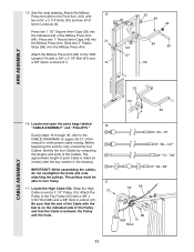
... 101 84 83 67 56 ARM ASSEMBLY CABLE ASSEMBLY 33 101 16. Locate and open the parts bags labeled ÒCABLE ASSEMBLYÓ and ÒPULLEYS.Ó 16 During steps 16 through 36, refer to verify proper cable routing. IMPORTANT: While assembling the cables, do not overtighten the bolts and nuts attaching the pulleys. Be sure that the end of each Cable is between the Pulley and the hook. 3 55...
... 101 84 83 67 56 ARM ASSEMBLY CABLE ASSEMBLY 33 101 16. Locate and open the parts bags labeled ÒCABLE ASSEMBLYÓ and ÒPULLEYS.Ó 16 During steps 16 through 36, refer to verify proper cable routing. IMPORTANT: While assembling the cables, do not overtighten the bolts and nuts attaching the pulleys. Be sure that the end of each Cable is between the Pulley and the hook. 3 55...
English Manual
Page 12
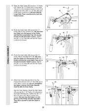
... Arm (47). Tighten the 3/8Ó x 2 1/2Ó Bolt (86) and the 3/8Ó Nylon Locknut (not shown). 58 31 86 50 48 CABLE ASSEMBLY 21. 18. tioned to hold the Cable in place. 12 Be sure that the Cable is in the groove of the Pulley and that the Cable 3 15 58 Trap (66) is turned to hold the Cable in place. Attach the Pulley...
... Arm (47). Tighten the 3/8Ó x 2 1/2Ó Bolt (86) and the 3/8Ó Nylon Locknut (not shown). 58 31 86 50 48 CABLE ASSEMBLY 21. 18. tioned to hold the Cable in place. 12 Be sure that the Cable is in the groove of the Pulley and that the Cable 3 15 58 Trap (66) is turned to hold the Cable in place. Attach the Pulley...
English Manual
Page 15
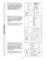
Locate the Military Press Cable (72). It should be threaded onto the end of the Cable so only a couple of the Low Cable (23) to the 29 Long ÒUÓ-Bracket (57) with a 1/4Ó Nylon Locknut (2) 3 and a 1/4Ó Flat Washer (10). Attach the end of threads are...CABLE ASSEMBLY 29. It should be threaded onto the end of the Cable only a couple of turns, as shown in 63 the inset drawing. Attach the Small ÒUÓ-Bracket (71) to the indicated Weight Tube (63) with a 1/4Ó Nylon Locknut (2) and 30 a 1/4Ó Flat Washer (10). Do not com- pletely tighten...
Locate the Military Press Cable (72). It should be threaded onto the end of the Cable so only a couple of the Low Cable (23) to the 29 Long ÒUÓ-Bracket (57) with a 1/4Ó Nylon Locknut (2) 3 and a 1/4Ó Flat Washer (10). Attach the end of threads are...CABLE ASSEMBLY 29. It should be threaded onto the end of the Cable only a couple of turns, as shown in 63 the inset drawing. Attach the Small ÒUÓ-Bracket (71) to the indicated Weight Tube (63) with a 1/4Ó Nylon Locknut (2) and 30 a 1/4Ó Flat Washer (10). Do not com- pletely tighten...
English Manual
Page 18
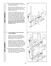
... for cable adjustment.) Tighten a 5/16Ó Nylon Jam Nut (93) onto the Bolt. Attach one end of the Seat to the Rear Seat Frame (100) with two 1/4Ó x 1/2Ó Screws (18). Slide a 5/16Ó Flat Washer (8) onto a 5/16Ó x 2 3/4Ó Bolt (11). Insert the 1/4Ó x 2 1/2Ó Carriage Bolt (92) through the lowest hole in a Seat Plate (37). Attach the Pulley to the Leg 36 Press Arm (96...
... for cable adjustment.) Tighten a 5/16Ó Nylon Jam Nut (93) onto the Bolt. Attach one end of the Seat to the Rear Seat Frame (100) with two 1/4Ó x 1/2Ó Screws (18). Slide a 5/16Ó Flat Washer (8) onto a 5/16Ó x 2 3/4Ó Bolt (11). Insert the 1/4Ó x 2 1/2Ó Carriage Bolt (92) through the lowest hole in a Seat Plate (37). Attach the Pulley to the Leg 36 Press Arm (96...

English Manual
Page 19
...; Square Inner Cap (32) into the Leg Lever (29) from the direction shown. Press a 1 1/2Ó Square Inner Cap (32) into the Leg Lever (29). 41 Lubricate the 5/16Ó x 2 1/4Ó Bolt (33). SEAT ASSEMBLY 39. Attach the Front Backrest (41) to the Front Upright with a 1/4Ó Flat Washer (10) and a 1/4Ó x 2Ó Machine Screw (81). 41. Tighten a 5/16Ó Nylon Locknut (3) with two...
...; Square Inner Cap (32) into the Leg Lever (29) from the direction shown. Press a 1 1/2Ó Square Inner Cap (32) into the Leg Lever (29). 41 Lubricate the 5/16Ó x 2 1/4Ó Bolt (33). SEAT ASSEMBLY 39. Attach the Front Backrest (41) to the Front Upright with a 1/4Ó Flat Washer (10) and a 1/4Ó x 2Ó Machine Screw (81). 41. Tighten a 5/16Ó Nylon Locknut (3) with two...
English Manual
Page 21
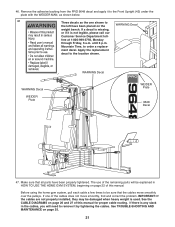
... cable routing. WA ¥ RNING tm¥mfw¥c¥idhaaohafaRMiyiRnlrDmeilseulnoapdsraaoiglrupedlwnneaesrsgodcneouuaast,edlsnlolutedlaaoafcrnlnbtiÕdlensoolwr Customer Service Department toll- until 6 p.m. See the CABLE DIAGRAMS on the WARNING Decal weight bench. Make sure that the cables move smoothly, find and correct the problem. IMPORTANT: If the cables are not properly installed, they may be damaged when heavy weight is any slack in HOW TO USE THE HOME GYM...
... cable routing. WA ¥ RNING tm¥mfw¥c¥idhaaohafaRMiyiRnlrDmeilseulnoapdsraaoiglrupedlwnneaesrsgodcneouuaast,edlsnlolutedlaaoafcrnlnbtiÕdlensoolwr Customer Service Department toll- until 6 p.m. See the CABLE DIAGRAMS on the WARNING Decal weight bench. Make sure that the cables move smoothly, find and correct the problem. IMPORTANT: If the cables are not properly installed, they may be damaged when heavy weight is any slack in HOW TO USE THE HOME GYM...
English Manual
Page 22
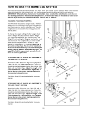
... attachments are in the correct starting position for the exercise to see how the home gym system should be adjusted. leys, the press arm, and the butterfly arms. The rear weight stack is touching the Weights, and turn the bent end downward. For some exercises, the Chain (52) should be attached between the Lat Bar and the High Cable so the Lat Bar is connected to the military press arm 26 and leg press. Use the WEIGHT RESISTANCE CHART...
... attachments are in the correct starting position for the exercise to see how the home gym system should be adjusted. leys, the press arm, and the butterfly arms. The rear weight stack is touching the Weights, and turn the bent end downward. For some exercises, the Chain (52) should be attached between the Lat Bar and the High Cable so the Lat Bar is connected to the military press arm 26 and leg press. Use the WEIGHT RESISTANCE CHART...
English Manual
Page 23
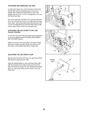
... some exercises, the Seat (13) must be attached to the leg lever. ATTACHING THE LEG LEVER TO THE LOW PULLEY STATION To use the Leg Lever (29), the seat must be sure that the chain is not attached to the front upright (see ATTACHING AND REMOVING THE SEAT above). Next, remove the Seat Knob (40) and the 5/16Ó x 2 3/4Ó Carriage Bolt (14) from the Leg Press Plate (95) and the Leg Press Arm...
... some exercises, the Seat (13) must be attached to the leg lever. ATTACHING THE LEG LEVER TO THE LOW PULLEY STATION To use the Leg Lever (29), the seat must be sure that the chain is not attached to the front upright (see ATTACHING AND REMOVING THE SEAT above). Next, remove the Seat Knob (40) and the 5/16Ó x 2 3/4Ó Carriage Bolt (14) from the Leg Press Plate (95) and the Leg Press Arm...

English Manual
Page 24
... is first used. Reattach the Pulley and Cable Trap. Remove the cable and re-install it. If the cables need to the next hole in the Rear Seat Frame (100). TROUBLE-SHOOTING AND MAINTENANCE Inspect and tighten all parts each time you use solvents. The home gym system can stretch slightly when it may have become twisted. If any worn parts immediately. To tighten the cables, insert the weight pin into the...
... is first used. Reattach the Pulley and Cable Trap. Remove the cable and re-install it. If the cables need to the next hole in the Rear Seat Frame (100). TROUBLE-SHOOTING AND MAINTENANCE Inspect and tighten all parts each time you use solvents. The home gym system can stretch slightly when it may have become twisted. If any worn parts immediately. To tighten the cables, insert the weight pin into the...

English Manual
Page 30
...; Bolt 3 1/2Ó Low Pulley VKR Backrest VKR Armrest Left VKR Arm Right VKR Arm 1/4Ó x 2Ó Machine Screw Handle 5Ó Plastic Grip Military Press Arm Rear Backrest 3/8Ó x 2 1/2Ó Bolt #8 x 1/2Ó Self-tapping Screw 3/8Ó x 3 3/4Ó Bolt 1 1/8Ó x 2 1/2Ó Plastic Bushing 1Ó x 7/8Ó Plastic Bushing Rubber Bumper 1/4Ó x 2 1/2Ó Carriage Bolt 5/16Ó Nylon Jam Nut Press Bracket Leg Press Plate Leg Press Arm Press Pin Bushing Leg Press Cable Rear Seat Frame Pivot Arm UserÕs Manual Exercise Poster...
...; Bolt 3 1/2Ó Low Pulley VKR Backrest VKR Armrest Left VKR Arm Right VKR Arm 1/4Ó x 2Ó Machine Screw Handle 5Ó Plastic Grip Military Press Arm Rear Backrest 3/8Ó x 2 1/2Ó Bolt #8 x 1/2Ó Self-tapping Screw 3/8Ó x 3 3/4Ó Bolt 1 1/8Ó x 2 1/2Ó Plastic Bushing 1Ó x 7/8Ó Plastic Bushing Rubber Bumper 1/4Ó x 2 1/2Ó Carriage Bolt 5/16Ó Nylon Jam Nut Press Bracket Leg Press Plate Leg Press Arm Press Pin Bushing Leg Press Cable Rear Seat Frame Pivot Arm UserÕs Manual Exercise Poster...

English Manual
Page 32
... 360 The actual resistance at each weight station. ÒTopÓ refers to the 6.5 lb. The butterfly arm resistance listed is the resistance for each weight station may vary due to the 12.5 lb. The other numbers refer to differences in individual weight plates, as well as friction between the cables, pulleys, and weight guides. 24 WEIGHT RESISTANCE CHART This chart shows the approximate weight resistance at each butterfly...
... 360 The actual resistance at each weight station. ÒTopÓ refers to the 6.5 lb. The butterfly arm resistance listed is the resistance for each weight station may vary due to the 12.5 lb. The other numbers refer to differences in individual weight plates, as well as friction between the cables, pulleys, and weight guides. 24 WEIGHT RESISTANCE CHART This chart shows the approximate weight resistance at each butterfly...
English Manual
Page 33
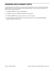
... (WEIDER¨ PRO 9648 Home Gym System). 3. To help us assist you, please be prepared to give the following information: 1. The SERIAL NUMBER of the product (see the PART LIST and EXPLODED DRAWING attached at 1-800-999-3756, Monday through Friday, 6 a.m. Part No. 149262 H02755-C Printed in Canada © 1998 ICON Health & Fitness, Inc. Mountain Time (excluding holidays). ORDERING REPLACEMENT PARTS To order replacement parts, simply call our Customer Service...
... (WEIDER¨ PRO 9648 Home Gym System). 3. To help us assist you, please be prepared to give the following information: 1. The SERIAL NUMBER of the product (see the PART LIST and EXPLODED DRAWING attached at 1-800-999-3756, Monday through Friday, 6 a.m. Part No. 149262 H02755-C Printed in Canada © 1998 ICON Health & Fitness, Inc. Mountain Time (excluding holidays). ORDERING REPLACEMENT PARTS To order replacement parts, simply call our Customer Service...


