
User Manual
Page 2
.... ICON is a registered trademark of whatsoever nature. ICON HEALTH & FITNESS, INC., 1500 S. 1000 W., LOGAN, UT 84321-9813 2 WEIDER is not responsible or liable for indirect, special or consequential damages arising out of or in workmanship and material, under this manual. The warranty...you . TABLE OF CONTENTS LIMITED WARRANTY 2 IMPORTANT PRECAUTIONS 3 BEFORE YOU BEGIN 4 ASSEMBLY 5 HOW TO USE THE HOME GYM SYSTEM 22 WEIGHT RESISTANCE CHART 24 TROUBLE-SHOOTING AND MAINTENANCE 25 CABLE DIAGRAMS 26 ORDERING REPLACEMENT PARTS Back Cover Note: A PART IDENTIFICATION CHART and a PART...
.... ICON is a registered trademark of whatsoever nature. ICON HEALTH & FITNESS, INC., 1500 S. 1000 W., LOGAN, UT 84321-9813 2 WEIDER is not responsible or liable for indirect, special or consequential damages arising out of or in workmanship and material, under this manual. The warranty...you . TABLE OF CONTENTS LIMITED WARRANTY 2 IMPORTANT PRECAUTIONS 3 BEFORE YOU BEGIN 4 ASSEMBLY 5 HOW TO USE THE HOME GYM SYSTEM 22 WEIGHT RESISTANCE CHART 24 TROUBLE-SHOOTING AND MAINTENANCE 25 CABLE DIAGRAMS 26 ORDERING REPLACEMENT PARTS Back Cover Note: A PART IDENTIFICATION CHART and a PART...

User Manual
Page 3
...are raised. Never release the press arm, butterfly arms, military press arm, leg lever, leg press plate, lat bar or nylon strap while weights are exercising, stop immediately and begin cooling down. 7. The home gym system is intended for protection. 4. ICON assumes no responsibility for foot protection...using . Always wear athletic shoes for personal injury or property damage sustained by or through the use the lat bar. 14. The weights will fall with pre-existing health problems. Read all of this or any time while exercising, stop immediately and make sure that ...
...are raised. Never release the press arm, butterfly arms, military press arm, leg lever, leg press plate, lat bar or nylon strap while weights are exercising, stop immediately and begin cooling down. 7. The home gym system is intended for protection. 4. ICON assumes no responsibility for foot protection...using . Always wear athletic shoes for personal injury or property damage sustained by or through the use the lat bar. 14. The weights will fall with pre-existing health problems. Read all of this or any time while exercising, stop immediately and make sure that ...
User Manual
Page 4
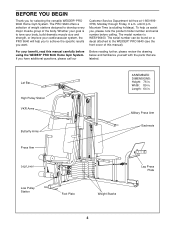
... muscle group of this manual carefully before calling. Length: 64 in . The serial number can be found on a decal attached to the WEIDER® PRO 9640 (see the front cover of the body. Width: 89 in . Customer Service Department toll-free at 1-800-9993756, Monday through Friday,...Arm Backrests Press Arm Leg Lever Low Pulley Station Foot Plate Weight Stacks Leg Press Plate 4 Whether your goal is WESY96400. For your cardiovascular system, the PRO 9640 will help us assist you for selecting the versatile WEIDER® PRO 9640 Home Gym System. If you want. The model number is...
... muscle group of this manual carefully before calling. Length: 64 in . The serial number can be found on a decal attached to the WEIDER® PRO 9640 (see the front cover of the body. Width: 89 in . Customer Service Department toll-free at 1-800-9993756, Monday through Friday,...Arm Backrests Press Arm Leg Lever Low Pulley Station Foot Plate Weight Stacks Leg Press Plate 4 Whether your goal is WESY96400. For your cardiovascular system, the PRO 9640 will help us assist you for selecting the versatile WEIDER® PRO 9640 Home Gym System. If you want. The model number is...
User Manual
Page 7
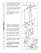
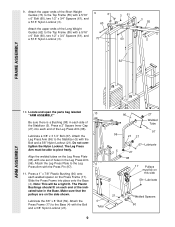
... two 5/16" Flat Washers (8), and two 5/16" Nylon Locknuts (3). 55 11 49 8 44 3 44 Crossbar 3 56 42 74 FRAME ASSEMBLY 5. Set two Weight Bumpers (19) on the bracket on the Base (4) as shown. Be sure that the pin grooves are all Nylon Locknuts used in the Stabilizer (5). Set...3 6 1 100 11 3 3 1 82 5 Pin Grooves 25 25 19 5-Bracket 4-Bracket Pin Grooves 19 7 Press a 1 3/4" Square Inner Cap (44) into the top of Weights. Attach the Handle (82) to the Front 11 Upright (42) with two 5/16" x 2 3/4" Bolts (11) and two 5/16" Nylon Locknuts (3). Press two 1" Round Inner...
... two 5/16" Flat Washers (8), and two 5/16" Nylon Locknuts (3). 55 11 49 8 44 3 44 Crossbar 3 56 42 74 FRAME ASSEMBLY 5. Set two Weight Bumpers (19) on the bracket on the Base (4) as shown. Be sure that the pin grooves are all Nylon Locknuts used in the Stabilizer (5). Set...3 6 1 100 11 3 3 1 82 5 Pin Grooves 25 25 19 5-Bracket 4-Bracket Pin Grooves 19 7 Press a 1 3/4" Square Inner Cap (44) into the top of Weights. Attach the Handle (82) to the Front 11 Upright (42) with two 5/16" x 2 3/4" Bolts (11) and two 5/16" Nylon Locknuts (3). Press two 1" Round Inner...
User Manual
Page 8
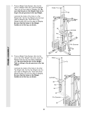
... Tube is sit- Lubricate the inside of the other Top Weight (65). Insert the 8 Holes Weight Tube into the stack of Weights. Set the Top Weight onto the front stack of Weights (25). Set the Top Weight onto the rear stack of Weights (25). 7. Lubricate the inside of Weights (25). Lubricate 65 Pin 63 64 Pin Grooves 25...
... Tube is sit- Lubricate the inside of the other Top Weight (65). Insert the 8 Holes Weight Tube into the stack of Weights. Set the Top Weight onto the front stack of Weights (25). Set the Top Weight onto the rear stack of Weights (25). 7. Lubricate the inside of Weights (25). Lubricate 65 Pin 63 64 Pin Grooves 25...
User Manual
Page 9
... place onto the Base (4). Slide the Press Frame into each end of the indicated tube in the Base. Attach the upper ends of the Long Weight Guides (62) to pivot freely. The Leg Press Arm must be on the Press Frame (17). Press a 1" x 7/8" Plastic Bushing (90) onto each side of the... Leg Press Arm (96). Attach the upper ends of the Short Weight Guides (73) to the Base (4) with one set of holes in each welded spacer on this side 59-Lubricate 21 Welded Spacers 90 Align the...
... place onto the Base (4). Slide the Press Frame into each end of the indicated tube in the Base. Attach the upper ends of the Long Weight Guides (62) to pivot freely. The Leg Press Arm must be on the Press Frame (17). Press a 1" x 7/8" Plastic Bushing (90) onto each side of the... Leg Press Arm (96). Attach the upper ends of the Short Weight Guides (73) to the Base (4) with one set of holes in each welded spacer on this side 59-Lubricate 21 Welded Spacers 90 Align the...
User Manual
Page 15
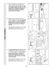
... (72). It should be threaded onto the end of the Cable so only a couple of the Low Cable (23) to the indi- 71 72 cated Weight Tube (63) with a 5/16" x 1 3/4" Bolt (24) and a 5/16" Nylon Locknut (3). 2 2 10 10 57 58 3 71 63 58 71 10 2 31. Attach 31 the Military Press... threaded onto the end of the Cable only a couple of turns, as shown in the inset drawing. Attach the Small "U"-Bracket (71) to the indicated Weight Tube (63) with a 5/16" x 1 3/4" Bolt (24) and a 5/16" Nylon Locknut (3). 10 2 15 57 23 24 10 2 72 71 24 10 2 CABLE ASSEMBLY 29...
... (72). It should be threaded onto the end of the Cable so only a couple of the Low Cable (23) to the indi- 71 72 cated Weight Tube (63) with a 5/16" x 1 3/4" Bolt (24) and a 5/16" Nylon Locknut (3). 2 2 10 10 57 58 3 71 63 58 71 10 2 31. Attach 31 the Military Press... threaded onto the end of the Cable only a couple of turns, as shown in the inset drawing. Attach the Small "U"-Bracket (71) to the indicated Weight Tube (63) with a 5/16" x 1 3/4" Bolt (24) and a 5/16" Nylon Locknut (3). 10 2 15 57 23 24 10 2 72 71 24 10 2 CABLE ASSEMBLY 29...
User Manual
Page 21
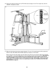
...If the cables are not properly installed, they may be damaged when heavy weight is any slack in HOW TO USE THE HOME GYM SYSTEM, beginning on page 22 of this manual. Remove the adhesive backing from the PRO 9640 decal and apply it by tightening the cables. See TROUBLE-SHOOTING AND MAINTENANCE... over the pulleys. Before using the home gym system, pull each cable a few times to the Front Upright (42) under the "WEIDER" nameplate as shown. 46 WEIDER Nameplate 42 PRO 9640 Decal 47. If there is used. If one of the remaining parts will need to remove it to be explained in the...
...If the cables are not properly installed, they may be damaged when heavy weight is any slack in HOW TO USE THE HOME GYM SYSTEM, beginning on page 22 of this manual. Remove the adhesive backing from the PRO 9640 decal and apply it by tightening the cables. See TROUBLE-SHOOTING AND MAINTENANCE... over the pulleys. Before using the home gym system, pull each cable a few times to the Front Upright (42) under the "WEIDER" nameplate as shown. 46 WEIDER Nameplate 42 PRO 9640 Decal 47. If there is used. If one of the remaining parts will need to remove it to be explained in the...
User Manual
Page 22
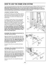
CHANGING THE WEIGHT SETTING The PRO 9640 features two weight stacks. Adjust the length of the Chain between the Lat Bar and...starting position for the exercise to be performed. leys, the press arm, and the butterfly arms. The rear weight stack is in the correct starting position for the exercise to be performed. Adjust the length of the Chain...home gym system should be set up for the exercise to be changed from the weight setting. To change the weight setting of either weight stack can be performed. HOW TO USE THE HOME GYM SYSTEM The instructions below describe...
CHANGING THE WEIGHT SETTING The PRO 9640 features two weight stacks. Adjust the length of the Chain between the Lat Bar and...starting position for the exercise to be performed. leys, the press arm, and the butterfly arms. The rear weight stack is in the correct starting position for the exercise to be performed. Adjust the length of the Chain...home gym system should be set up for the exercise to be changed from the weight setting. To change the weight setting of either weight stack can be performed. HOW TO USE THE HOME GYM SYSTEM The instructions below describe...
User Manual
Page 24
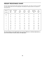
... 320 29 40 50 80 72 146 95 166 120 210 140 240 160 268 180 325 205 360 The actual resistance at each weight station. "Top" refers to the 12.5 lb. The butterfly arm resistance listed is the resistance for each butterfly arm. The other ...numbers refer to the 6.5 lb. weight plates. WEIGHT RESISTANCE CHART This chart shows the approximate weight resistance at each weight station may vary due to differences in individual weight plates, as well as friction between the cables, pulleys, and...
... 320 29 40 50 80 72 146 95 166 120 210 140 240 160 268 180 325 205 360 The actual resistance at each weight station. "Top" refers to the 12.5 lb. The butterfly arm resistance listed is the resistance for each butterfly arm. The other ...numbers refer to the 6.5 lb. weight plates. WEIGHT RESISTANCE CHART This chart shows the approximate weight resistance at each weight station may vary due to differences in individual weight plates, as well as friction between the cables, pulleys, and...
User Manual
Page 25
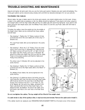
.... If any slack is first used. Reattach the Pulley and Cable Trap. Tighten the 1/4" Nylon Locknut (2) that the Cable and Pulley move smoothly. The top weight will need to the Small "U"Bracket (71). 1 66 21 57 15 12 2 23 or 99 2 72 71 2 58 71 2 3 The Military Press Cable (72) can... Cable, and both 5/16" Nylon Jam Nuts (93) from the Cable Trap (66), Pulley, and Long "U"-Bracket. If the cables need to slip off the weight stack. TIGHTENING THE CABLES Woven cable, the type of this manual. 25 Remove the 5/16" x 2 3/4" Bolt (11), the 5/16" Washer (8), the end of the Cable...
.... If any slack is first used. Reattach the Pulley and Cable Trap. Tighten the 1/4" Nylon Locknut (2) that the Cable and Pulley move smoothly. The top weight will need to the Small "U"Bracket (71). 1 66 21 57 15 12 2 23 or 99 2 72 71 2 58 71 2 3 The Military Press Cable (72) can... Cable, and both 5/16" Nylon Jam Nuts (93) from the Cable Trap (66), Pulley, and Long "U"-Bracket. If the cables need to slip off the weight stack. TIGHTENING THE CABLES Woven cable, the type of this manual. 25 Remove the 5/16" x 2 3/4" Bolt (11), the 5/16" Washer (8), the end of the Cable...
User Manual
Page 26
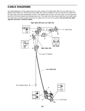
... come off the pulleys. High Cable (58) and Low Cable (23) 7 5 23 4 1-High Pulley TOP VIEW 6 High Cable (58) 5-Long "U"-Bracket Low Cable (23) Front Weight Stack-8 4 3 2 1-Low Pulley 26 Use the diagrams to be positioned so that the cable traps do not touch or bind the cables. CABLE DIAGRAMS The...
... come off the pulleys. High Cable (58) and Low Cable (23) 7 5 23 4 1-High Pulley TOP VIEW 6 High Cable (58) 5-Long "U"-Bracket Low Cable (23) Front Weight Stack-8 4 3 2 1-Low Pulley 26 Use the diagrams to be positioned so that the cable traps do not touch or bind the cables. CABLE DIAGRAMS The...

User Manual
Page 27
Military Press Cable (72) and Leg Press Cable (99) 2 Military Press Cable (72) Rear Weight Stack-1 4 6-Pivot Arm 5 1-Long "U"-Bracket 3 2 4-Rear Seat Frame 3 Leg Press Cable (99) 27
Military Press Cable (72) and Leg Press Cable (99) 2 Military Press Cable (72) Rear Weight Stack-1 4 6-Pivot Arm 5 1-Long "U"-Bracket 3 2 4-Rear Seat Frame 3 Leg Press Cable (99) 27
User Manual
Page 33
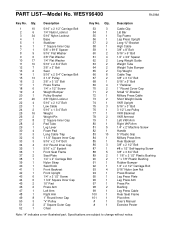
... 5/16" Flat Washer 3/8" Flat Washer 1/4" Flat Washer 5/16" x 2 3/4" Bolt 3/8" x 2" Bolt Seat 5/16" x 2 3/4" Carriage Bolt 3 1/2" Pulley 3/8" x 3 1/2" Bolt Press Frame 1/4" x 1/2" Screw Weight Bumper Pulley Bracket 3/8" Nylon Locknut 5/16" x 2 1/2" Bolt Low Cable 5/16" x 1 3/4" Bolt Weight Weight Pin 2" Square Inner Cap Pad Tube Leg Lever Foam Pad Long Cable Trap 1 1/2" Square Inner Cap 5/16" x 2 1/4" Bolt 3/4" Round Inner...
... 5/16" Flat Washer 3/8" Flat Washer 1/4" Flat Washer 5/16" x 2 3/4" Bolt 3/8" x 2" Bolt Seat 5/16" x 2 3/4" Carriage Bolt 3 1/2" Pulley 3/8" x 3 1/2" Bolt Press Frame 1/4" x 1/2" Screw Weight Bumper Pulley Bracket 3/8" Nylon Locknut 5/16" x 2 1/2" Bolt Low Cable 5/16" x 1 3/4" Bolt Weight Weight Pin 2" Square Inner Cap Pad Tube Leg Lever Foam Pad Long Cable Trap 1 1/2" Square Inner Cap 5/16" x 2 1/4" Bolt 3/4" Round Inner...


