
English Manual
Page 1
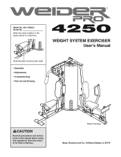
Patent Pending Sears, Roebuck and Co., Hoffman Estates, IL 60179 Write the serial number in this manual before using this manual for reference. Model No. 831.15402.2 Serial No. WEIGHT SYSTEM EXERCISER User's Manual Serial Number Decal (under seat) • Assembly • Adjustments • Troubleshooting • Part List and Drawing CAUTION Read all precautions and instructions in the space above for future reference. Save this equipment.
Patent Pending Sears, Roebuck and Co., Hoffman Estates, IL 60179 Write the serial number in this manual before using this manual for reference. Model No. 831.15402.2 Serial No. WEIGHT SYSTEM EXERCISER User's Manual Serial Number Decal (under seat) • Assembly • Adjustments • Troubleshooting • Part List and Drawing CAUTION Read all precautions and instructions in the space above for future reference. Save this equipment.
English Manual
Page 2
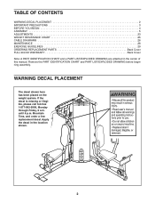
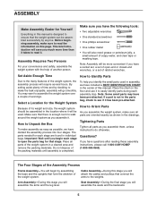
until 6 p.m. Apply the decal in the center of this manual. TABLE OF CONTENTS WARNING DECAL PLACEMENT 2 IMPORTANT PRECAUTIONS 3 BEFORE YOU BEGIN 4 ASSEMBLY 5 ADJUSTMENTS 23 WEIGHT RESISTANCE CHART 25 CABLE DIAGRAMS 26 MAINTENANCE 28 EXERCISE GUIDELINES 29 ORDERING REPLACEMENT PARTS Back Cover FULL 90-DAY WARRANTY Back Cover Note: A PART IDENTIFICATION CHART and a PART LIST/EXPLODED DRAWING are attached in the location shown. 2 WARNING DECAL PLACEMENT The decal shown here has been placed on the weight system. Mountain Time, and order a free replacement decal. Remove the ...
until 6 p.m. Apply the decal in the center of this manual. TABLE OF CONTENTS WARNING DECAL PLACEMENT 2 IMPORTANT PRECAUTIONS 3 BEFORE YOU BEGIN 4 ASSEMBLY 5 ADJUSTMENTS 23 WEIGHT RESISTANCE CHART 25 CABLE DIAGRAMS 26 MAINTENANCE 28 EXERCISE GUIDELINES 29 ORDERING REPLACEMENT PARTS Back Cover FULL 90-DAY WARRANTY Back Cover Note: A PART IDENTIFICATION CHART and a PART LIST/EXPLODED DRAWING are attached in the location shown. 2 WARNING DECAL PLACEMENT The decal shown here has been placed on the weight system. Mountain Time, and order a free replacement decal. Remove the ...
English Manual
Page 3
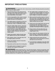
Read all instructions in this or any worn parts immediately. 11. Use the weight system only as you feel pain or dizziness at all instructions before using the weight system. 1. Replace all parts regularly. The weights will fall with the lock pin and lock after exercising to prevent unauthorized use of the weight system (see LOCKING THE WEIGHT STACK on the weight system before using the weight system. WARNING: Before beginning this manual. 10. This is intended for persons over the age of 35 or persons with the included weight. The weight system is enough clearance ...
Read all instructions in this or any worn parts immediately. 11. Use the weight system only as you feel pain or dizziness at all instructions before using the weight system. 1. Replace all parts regularly. The weights will fall with the lock pin and lock after exercising to prevent unauthorized use of the weight system (see LOCKING THE WEIGHT STACK on the weight system before using the weight system. WARNING: Before beginning this manual. 10. This is intended for persons over the age of 35 or persons with the included weight. The weight system is enough clearance ...
English Manual
Page 4
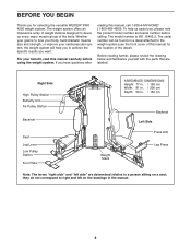
... are determined relative to tone your body, build dramatic muscle size and strength, or improve your benefit, read this manual for selecting the versatile WEIDER® PRO 4250 weight system. Right Side High Pulley Station Butterfly Arm Ab Pulley Station Backrest Seat Leg Lever Low Pulley Station Foot Plate ASSEMBLED DIMENSIONS: Height: 77...
... are determined relative to tone your body, build dramatic muscle size and strength, or improve your benefit, read this manual for selecting the versatile WEIDER® PRO 4250 weight system. Right Side High Pulley Station Butterfly Arm Ab Pulley Station Backrest Seat Leg Lever Low Pulley Station Foot Plate ASSEMBLED DIMENSIONS: Height: 77...
English Manual
Page 5
Before beginning assembly, make assembly as easy as you have the following tools: • Two adjustable wrenches • One standard screwdriver • One phillips screwdriver • One rubber mallet • You will go smoothly. You may have divided the assembly process into four stages. How to Unpack the Box To make sure to read it . Place the chart on this page. If a part is not in the location where it will be assembled successfully by anyone. Questions? Cable Assembly-During this manual. Set Aside Enough Time How to Identify Parts Due to the weights. ...
Before beginning assembly, make assembly as easy as you have the following tools: • Two adjustable wrenches • One standard screwdriver • One phillips screwdriver • One rubber mallet • You will go smoothly. You may have divided the assembly process into four stages. How to Unpack the Box To make sure to read it . Place the chart on this page. If a part is not in the location where it will be assembled successfully by anyone. Questions? Cable Assembly-During this manual. Set Aside Enough Time How to Identify Parts Due to the weights. ...
English Manual
Page 6
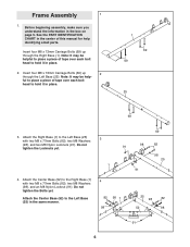
Frame Assembly 1 1. Note: It may be helpful to place a piece of tape over each bolt head to hold it in the center of this manual for help - ful to place a piece of tape over each bolt head to the Left Base (25) 3 with two M8 x 77mm Bolts (82), two M8 Washers (98), and an M8 Nylon Locknut (91). Attach the Right Base (1) to hold it in place. 2. Attach the Center Base (52) to the Right Base (1) with two M8 x 77mm Bolts (82), two M8 Washers (98), and two M8 Nylon Locknuts (91). Note: It may be help identifying small parts. Attach the Center Base (52) to ...
Frame Assembly 1 1. Note: It may be helpful to place a piece of tape over each bolt head to hold it in the center of this manual for help - ful to place a piece of tape over each bolt head to the Left Base (25) 3 with two M8 x 77mm Bolts (82), two M8 Washers (98), and an M8 Nylon Locknut (91). Attach the Right Base (1) to hold it in place. 2. Attach the Center Base (52) to the Right Base (1) with two M8 x 77mm Bolts (82), two M8 Washers (98), and two M8 Nylon Locknuts (91). Note: It may be help identifying small parts. Attach the Center Base (52) to ...
English Manual
Page 7
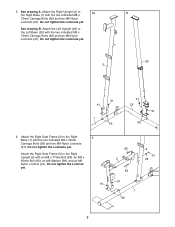
Do not tighten the Locknuts yet. See drawing B. 5. Attach the Left Upright (26) to the Right 6 Base (1) with the two indicated M8 x 72mm Carriage Bolts (69) and two M8 Nylon Locknuts (91). Do not tighten the Locknuts yet. Do not tighten the Locknuts yet. 2 B 26 91 91 1 69 91 25 91 69 6. Attach the Right Seat Frame (3) to the Left Base (25) with the two indicated M8 x 72mm Carriage Bolts (69) and two M8 Nylon Locknuts (91). Attach the Right Seat Frame (3) to 5A the Right Base (1) with an M8 x 77mm Bolt (82), an M8 x 95mm Bolt (83), an M8 Washer (98), and an M8 ...
Do not tighten the Locknuts yet. See drawing B. 5. Attach the Left Upright (26) to the Right 6 Base (1) with the two indicated M8 x 72mm Carriage Bolts (69) and two M8 Nylon Locknuts (91). Do not tighten the Locknuts yet. Do not tighten the Locknuts yet. 2 B 26 91 91 1 69 91 25 91 69 6. Attach the Right Seat Frame (3) to the Left Base (25) with the two indicated M8 x 72mm Carriage Bolts (69) and two M8 Nylon Locknuts (91). Attach the Right Seat Frame (3) to 5A the Right Base (1) with an M8 x 77mm Bolt (82), an M8 x 95mm Bolt (83), an M8 Washer (98), and an M8 ...
English Manual
Page 8
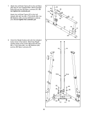
Do not tighten the Locknuts yet. 7 98 91 26 82 Attach the Left Seat Frame (27) to the bottom. Attach the Weight Guides inside of the Center Base (52) with the two indicated M8 x 72mm Carriage Bolts (69) and two M8 Nylon Locknuts (91). Orient the Weight Guides (44) with the indicated 8 holes closer to the Left Upright (26) with two M8 x 77mm Bolts (82), two M8 Washers (98), and two M8 Nylon Locknuts 98 82 27 (91). Do not tighten the Locknuts yet. 25 91 91 8. 7. Attach the Left Seat Frame (27) to the Left Base (25) with two M8 x 77mm Bolts (82), four M8 Washers (98),...
Do not tighten the Locknuts yet. 7 98 91 26 82 Attach the Left Seat Frame (27) to the bottom. Attach the Weight Guides inside of the Center Base (52) with the two indicated M8 x 72mm Carriage Bolts (69) and two M8 Nylon Locknuts (91). Orient the Weight Guides (44) with the indicated 8 holes closer to the Left Upright (26) with two M8 x 77mm Bolts (82), two M8 Washers (98), and two M8 Nylon Locknuts 98 82 27 (91). Do not tighten the Locknuts yet. 25 91 91 8. 7. Attach the Left Seat Frame (27) to the Left Base (25) with two M8 x 77mm Bolts (82), four M8 Washers (98),...
English Manual
Page 9
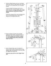
Make sure the pin on the indicated side, onto the Weight Guides. Make 82 98 sure the Weight Guides (44) are behind the Right Top Frame. 98 5 91 91 44 44 2 11. Slide two Weight Bumpers (45) onto the Weight 9 Guides (44). Insert the Weight Tube into the Weight Tube (47). Slide the Top Weight onto the Weight Guides (44). 44 56 Grease Pin 47 Groove 46 55 Pin 45 45 Holes 10. Attach a Weight Guide (44) to the Right 10 Upright (2) with the pin holes on the Weight Tube sits in the groove in the Top Weight (56) with an M8 x 77mm Bolt (82), two M8 Washers (98...
Make sure the pin on the indicated side, onto the Weight Guides. Make 82 98 sure the Weight Guides (44) are behind the Right Top Frame. 98 5 91 91 44 44 2 11. Slide two Weight Bumpers (45) onto the Weight 9 Guides (44). Insert the Weight Tube into the Weight Tube (47). Slide the Top Weight onto the Weight Guides (44). 44 56 Grease Pin 47 Groove 46 55 Pin 45 45 Holes 10. Attach a Weight Guide (44) to the Right 10 Upright (2) with the pin holes on the Weight Tube sits in the groove in the Top Weight (56) with an M8 x 77mm Bolt (82), two M8 Washers (98...
English Manual
Page 10
Attach the Left Top Frame (36) to the Right Top Frame (5) with four M8 x 77mm Bolts (82), two M8 Washers (98), a Support Plate (31), and four M8 Nylon Locknuts (91). Do not tighten the Locknuts yet. 91 82 36 31 91 91 26 14. Do not tighten the Locknuts yet. Attach the Butterfly Frame (14) to the Right Top Frame (5) with two M8 x 77mm Bolts (82), two M8 Washers (98), and two M8 Nylon Locknuts (91). Wet the lower end of two Arm Bushing (23) with soapy water. Make sure the bolt head fits inside of the hole in steps 3-14. 14 82 98 98 5 91 91 98 85 98 91 2 14 Arm Assembly 15....
Attach the Left Top Frame (36) to the Right Top Frame (5) with four M8 x 77mm Bolts (82), two M8 Washers (98), a Support Plate (31), and four M8 Nylon Locknuts (91). Do not tighten the Locknuts yet. 91 82 36 31 91 91 26 14. Do not tighten the Locknuts yet. Attach the Butterfly Frame (14) to the Right Top Frame (5) with two M8 x 77mm Bolts (82), two M8 Washers (98), and two M8 Nylon Locknuts (91). Wet the lower end of two Arm Bushing (23) with soapy water. Make sure the bolt head fits inside of the hole in steps 3-14. 14 82 98 98 5 91 91 98 85 98 91 2 14 Arm Assembly 15....

English Manual
Page 11
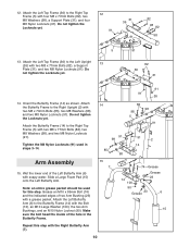
Attach the Leg Lever (4) to the Left Base (25) with the Bolt and an M10 Nylon Locknut (90). Do not overtighten the Locknut; Do not overtighten the Locknut; Grease an M10 x 106mm Bolt (72). Attach the Press Frame to the Right Seat Frame (3) with the other Press Arm (30). 34 32 30 90 99 101 101 99 30 77 11 the Leg Lever must be able to pivot easily. 17 Tube 26 90 29 Grease 72 25 18. the Press Frame must be able to pivot easily. 16 4 "U"-rod 90 89 96 59 3 Grease 60 17. 16. Grease an M10 x 72mm Bolt (60). Attach a Press Handle (32) to the Press Arm (30) ...
Attach the Leg Lever (4) to the Left Base (25) with the Bolt and an M10 Nylon Locknut (90). Do not overtighten the Locknut; Do not overtighten the Locknut; Grease an M10 x 106mm Bolt (72). Attach the Press Frame to the Right Seat Frame (3) with the other Press Arm (30). 34 32 30 90 99 101 101 99 30 77 11 the Leg Lever must be able to pivot easily. 17 Tube 26 90 29 Grease 72 25 18. the Press Frame must be able to pivot easily. 16 4 "U"-rod 90 89 96 59 3 Grease 60 17. 16. Grease an M10 x 72mm Bolt (60). Attach a Press Handle (32) to the Press Arm (30) ...
English Manual
Page 12
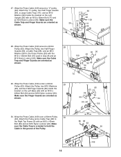
Grease an M10 x 106mm Bolt (72). Attach the 20 Leg Press Frame (28) to pivot easily. 30 91 29 28 21. Do not overtighten the Locknut; Do not overtighten the Locknut; Grease an M10 x 75mm Bolt (76). Repeat this step with the Bolt and an M10 Nylon Locknut (90). Locate the Press Cable (109). 19. the Cable must be able to the Left Base (25) with the other Press Arm (30). 86 30 20. the Leg Press Frame must be able to pivot easily. 12 109 37 28 91 the Foot Plate must be able to pivot easily. 90 25 72 90 Grease 76 38 28 Cable Assembly 22 22. Attach the ...
Grease an M10 x 106mm Bolt (72). Attach the 20 Leg Press Frame (28) to pivot easily. 30 91 29 28 21. Do not overtighten the Locknut; Do not overtighten the Locknut; Grease an M10 x 75mm Bolt (76). Repeat this step with the Bolt and an M10 Nylon Locknut (90). Locate the Press Cable (109). 19. the Cable must be able to the Left Base (25) with the other Press Arm (30). 86 30 20. the Leg Press Frame must be able to pivot easily. 12 109 37 28 91 the Foot Plate must be able to pivot easily. 90 25 72 90 Grease 76 38 28 Cable Assembly 22 22. Attach the ...
English Manual
Page 13
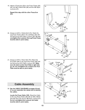
Make sure the Cable Trap and Finger Guards are oriented as shown. 29 109 66 70 66 99 63 68 13 Make sure the Cable Trap and the Finger Guards are oriented as shown. 24. Wrap the Press Cable (109) around a "V"-pulley (62). Attach the "V"-pulley, two Half Finger Guards (66), and two M10 Washers (99) to the Left Upright (26) with an M10 x 115mm Bolt (71) and an M10 Nylon Locknut (90). Make sure the Finger Guards are oriented as shown. 23 27 90 66 22 63 68 99 66 109 24 28 90 109 62 66 71 99 99 66 25. Make sure the Cable Trap and Finger Guards are oriented as ...
Make sure the Cable Trap and Finger Guards are oriented as shown. 29 109 66 70 66 99 63 68 13 Make sure the Cable Trap and the Finger Guards are oriented as shown. 24. Wrap the Press Cable (109) around a "V"-pulley (62). Attach the "V"-pulley, two Half Finger Guards (66), and two M10 Washers (99) to the Left Upright (26) with an M10 x 115mm Bolt (71) and an M10 Nylon Locknut (90). Make sure the Finger Guards are oriented as shown. 23 27 90 66 22 63 68 99 66 109 24 28 90 109 62 66 71 99 99 66 25. Make sure the Cable Trap and Finger Guards are oriented as ...
English Manual
Page 14
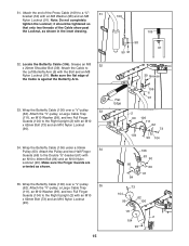
Attach the Pulley and a Cable Trap (68) to the Right Top Frame (5) with the M10 x 134mm Bolt (70) used in the groove of the Pulley. 80 68 63 5 90 109 14 Make sure the Cable Trap and Finger Guards are oriented as shown. 99 66 90 66 63 99 64 109 25 30. Make sure the Finger Guards are oriented as shown. 27 77 26 90 66 99 62 109 111 66 28. Wrap the Press Cable (109) over a 90mm Pulley 30 (63). Wrap the Press Cable (109) around a "V"-pulley (62). Attach the Pulley, two Half Finger Guards (66), a Cable Trap (68), and an M10 Washer (99) to hold the Cable in step ...
Attach the Pulley and a Cable Trap (68) to the Right Top Frame (5) with the M10 x 134mm Bolt (70) used in the groove of the Pulley. 80 68 63 5 90 109 14 Make sure the Cable Trap and Finger Guards are oriented as shown. 99 66 90 66 63 99 64 109 25 30. Make sure the Finger Guards are oriented as shown. 27 77 26 90 66 99 62 109 111 66 28. Wrap the Press Cable (109) over a 90mm Pulley 30 (63). Wrap the Press Cable (109) around a "V"-pulley (62). Attach the Pulley, two Half Finger Guards (66), a Cable Trap (68), and an M10 Washer (99) to hold the Cable in step ...
English Manual
Page 15
it should be tightened so that only two threads of the Cable show past the Locknut, as shown. 35. Attach the Pulley and two Half Finger Guards (66) to the Double "U"-bracket (61) with an M10 x 62mm Bolt (73) and an M10 Nylon Locknut (90). 34. Attach the "V"-pulley, a Large Cable Trap (111), an M10 Washer (99), and two Full Finger Guards (104) to a "U"- 31 bracket (50) with the Bolt and an M8 Nylon Locknut (91). Make sure the Finger Guards are oriented as shown in the inset drawing. 32. Attach the end of the Cable is against the Butterfly Arm. 33. Make sure the...
it should be tightened so that only two threads of the Cable show past the Locknut, as shown. 35. Attach the Pulley and two Half Finger Guards (66) to the Double "U"-bracket (61) with an M10 x 62mm Bolt (73) and an M10 Nylon Locknut (90). 34. Attach the "V"-pulley, a Large Cable Trap (111), an M10 Washer (99), and two Full Finger Guards (104) to a "U"- 31 bracket (50) with the Bolt and an M8 Nylon Locknut (91). Make sure the Finger Guards are oriented as shown in the inset drawing. 32. Attach the end of the Cable is against the Butterfly Arm. 33. Make sure the...
English Manual
Page 16
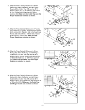
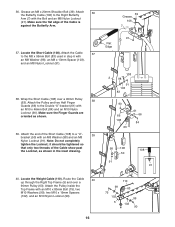
Locate the Short Cable (108). Attach the Cable 37 to the Double "U"-bracket (61) with an M10 x 46mm Bolt (84) and an M10 Nylon Locknut (90). Route the Cable 40 up through the Right Top Frame (5) and over a 90mm Pulley (63). Note: Do not completely tighten the Locknut; 36. Attach the Pulley and two Half Finger 38 Guards (66) to the M8 x 95mm Bolt (83) used in the inset drawing. 39 Grease 106 7 91 Flat Edge 108 2 98 91 103 83 90 66 108 63 61 66 84 98 108 50 91 108 91 40. Attach the end of the Short Cable (108) to the Right Butterfly Arm (7) with an M8 ...
Locate the Short Cable (108). Attach the Cable 37 to the Double "U"-bracket (61) with an M10 x 46mm Bolt (84) and an M10 Nylon Locknut (90). Route the Cable 40 up through the Right Top Frame (5) and over a 90mm Pulley (63). Note: Do not completely tighten the Locknut; 36. Attach the Pulley and two Half Finger 38 Guards (66) to the M8 x 95mm Bolt (83) used in the inset drawing. 39 Grease 106 7 91 Flat Edge 108 2 98 91 103 83 90 66 108 63 61 66 84 98 108 50 91 108 91 40. Attach the end of the Short Cable (108) to the Right Butterfly Arm (7) with an M8 ...

English Manual
Page 17
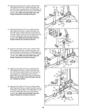
Attach the Pulley, a Cable Trap (68), and two Half Finger Guards (66) at the second hole from the top of the Pulley. 44 Attach pulley on the Right Top Frame (5) with an M10 x 80mm Bolt (75), two M10 Washers (99), two M10 x 19mm Spacers (102), and an M10 Nylon Locknut (90). 75 99 102 99 90 63 110 5 42. Make sure the Cable Trap and Finger Guards are oriented as shown. 43. Wrap the Weight Cable (110) over a 90mm Pulley (63). Attach the Pulley inside the Top Frame with an M10 x 43mm Bolt (80) and an M10 Nylon Locknut (90). Wrap the Weight Cable (110) over a 90mm Pulley (...
Attach the Pulley, a Cable Trap (68), and two Half Finger Guards (66) at the second hole from the top of the Pulley. 44 Attach pulley on the Right Top Frame (5) with an M10 x 80mm Bolt (75), two M10 Washers (99), two M10 x 19mm Spacers (102), and an M10 Nylon Locknut (90). 75 99 102 99 90 63 110 5 42. Make sure the Cable Trap and Finger Guards are oriented as shown. 43. Wrap the Weight Cable (110) over a 90mm Pulley (63). Attach the Pulley inside the Top Frame with an M10 x 43mm Bolt (80) and an M10 Nylon Locknut (90). Wrap the Weight Cable (110) over a 90mm Pulley (...
English Manual
Page 18
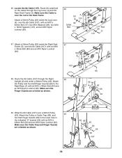
Make sure the Cable is over a 90mm Pulley (63). Make sure the Finger Guards are oriented as shown. 107 2 90 66 63 66 64 1 49. Make sure the Cable Trap and Finger Guards are oriented as shown. 90 66 68 50 66 64 63 107 18 Attach a 90mm Pulley (63) inside the Right Seat 47 Frame (3), over the Ab Cable (107), with an M10 x 48mm Bolt (64) and an M10 Nylon Locknut (90). 46. Attach the Pulley and two Half Finger Guards (66) to the lower hole in the Seat Frame. Route the small ball on the Cable through the Right 48 Upright (2) and under a 90mm Pulley (63). Route the Ab...
Make sure the Cable is over a 90mm Pulley (63). Make sure the Finger Guards are oriented as shown. 107 2 90 66 63 66 64 1 49. Make sure the Cable Trap and Finger Guards are oriented as shown. 90 66 68 50 66 64 63 107 18 Attach a 90mm Pulley (63) inside the Right Seat 47 Frame (3), over the Ab Cable (107), with an M10 x 48mm Bolt (64) and an M10 Nylon Locknut (90). 46. Attach the Pulley and two Half Finger Guards (66) to the lower hole in the Seat Frame. Route the small ball on the Cable through the Right 48 Upright (2) and under a 90mm Pulley (63). Route the Ab...
English Manual
Page 19
Wrap the Ab Cable (107) under a 90mm Pulley 54 (63). Make sure the Cable Trap and Finger Guards are oriented as shown. 52. Make sure the Cable Trap and Finger Guards are oriented as shown. 54. Attach the Pulley, a Cable Trap (68) and two Half Finger Guards (66) to the Right Base (1) with an M10 x 48mm Bolt (64) and an M10 Nylon Locknut (90). Make sure the Cable Trap and Finger Guards are oriented as shown. 90 66 107 63 1 68 51. Wrap the Ab Cable (107) over a 90mm Pulley 51 (63). Wrap the Ab Cable (107) under a 90mm Pulley 50 (63). Wrap the Ab Cable (107) ...
Wrap the Ab Cable (107) under a 90mm Pulley 54 (63). Make sure the Cable Trap and Finger Guards are oriented as shown. 52. Make sure the Cable Trap and Finger Guards are oriented as shown. 54. Attach the Pulley, a Cable Trap (68) and two Half Finger Guards (66) to the Right Base (1) with an M10 x 48mm Bolt (64) and an M10 Nylon Locknut (90). Make sure the Cable Trap and Finger Guards are oriented as shown. 90 66 107 63 1 68 51. Wrap the Ab Cable (107) over a 90mm Pulley 51 (63). Wrap the Ab Cable (107) under a 90mm Pulley 50 (63). Wrap the Ab Cable (107) ...
English Manual
Page 20
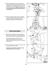
Wrap the Ab Cable (107) over the Cable. 56. Engage the Knob (43) into the Weight Tube (not shown) until it is tight. 78 97 58. Tighten the Weight Cable (110) into the Upright and Backrest Frame, and turn it clockwise until all the slack is over a 90mm Pulley 55 (63). Attach the Press Backrest (113) to the Backrest Frame (53) with an M10 x 106mm Bolt (72), an M10 Washer (99), and an M10 Nylon Locknut (90). Attach the Pulley and the two Quarter Finger Guards (105) to the Left Seat Frame (27) with 58 four M6 x 16mm Screws (88). 8 Repeat this step with the other Seat...
Wrap the Ab Cable (107) over the Cable. 56. Engage the Knob (43) into the Weight Tube (not shown) until it is tight. 78 97 58. Tighten the Weight Cable (110) into the Upright and Backrest Frame, and turn it clockwise until all the slack is over a 90mm Pulley 55 (63). Attach the Press Backrest (113) to the Backrest Frame (53) with an M10 x 106mm Bolt (72), an M10 Washer (99), and an M10 Nylon Locknut (90). Attach the Pulley and the two Quarter Finger Guards (105) to the Left Seat Frame (27) with 58 four M6 x 16mm Screws (88). 8 Repeat this step with the other Seat...