English Owners Manual
Page 5
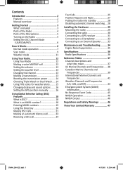
... the Radio 5 Setting the UIC Channel Mode (USA/CAN/INT 6 How It Works 6 Normal mode operation 7 Scan mode 9 Weather mode 11 Using Your Radio 12 Using Your Radio 12 Making a voice MAYDAY call 13 Setting the volume 13 Setting the squelch level 13 Changing the channel 13 Making a transmission 13 Boosting the transmission power 14 Choosing Triple Watch or Dual Watch...... 14 Using FIPS codes for weather alerts......... 15 Changing display and sound options ....... 16 Setting the GPS position manually 16 Using Digital...
... the Radio 5 Setting the UIC Channel Mode (USA/CAN/INT 6 How It Works 6 Normal mode operation 7 Scan mode 9 Weather mode 11 Using Your Radio 12 Using Your Radio 12 Making a voice MAYDAY call 13 Setting the volume 13 Setting the squelch level 13 Changing the channel 13 Making a transmission 13 Boosting the transmission power 14 Choosing Triple Watch or Dual Watch...... 14 Using FIPS codes for weather alerts......... 15 Changing display and sound options ....... 16 Setting the GPS position manually 16 Using Digital...
English Owners Manual
Page 6
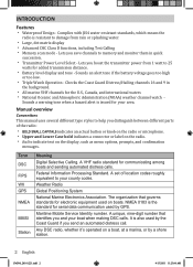
... Atmospheric Administration (NOAA) weather channel watch - Federal Information Processing Standard. A set of the radio: xx BOLD SMALL CAPITALS indicates an actual button or knob on the radio or microphone. NMEA 0183 is resistant to damage from 1 watt to 25 watts for serial data communication used by a shore station. 2 English UM380_20101221.indd 2 4/13/2011 11:25:06 AM A unique, nine-digit number that governs standards...
... Atmospheric Administration (NOAA) weather channel watch - Federal Information Processing Standard. A set of the radio: xx BOLD SMALL CAPITALS indicates an actual button or knob on the radio or microphone. NMEA 0183 is resistant to damage from 1 watt to 25 watts for serial data communication used by a shore station. 2 English UM380_20101221.indd 2 4/13/2011 11:25:06 AM A unique, nine-digit number that governs standards...

English Owners Manual
Page 8
... an option on a menu or Change the transmit power (see page 14). Move up the channels. Display the normal menu. Select the nature of the Radio LCD display CHANNEL UP & CHANNEL DOWN buttons VOLUME-PWR (power) knob (turn clockwise to increase volume) ENT1W/25W button Microphone cord CALL-MENU WX-MEM button button CLR-SCAN (channel scan) button DISTRESS button 16/9-TRI (triple/dualwatch) button SQUELCH knob (turn clockwise to decrease channel noise) Button ENT-1W/25W Channel Up Channel Down 16/9-TRI...
... an option on a menu or Change the transmit power (see page 14). Move up the channels. Display the normal menu. Select the nature of the Radio LCD display CHANNEL UP & CHANNEL DOWN buttons VOLUME-PWR (power) knob (turn clockwise to increase volume) ENT1W/25W button Microphone cord CALL-MENU WX-MEM button button CLR-SCAN (channel scan) button DISTRESS button 16/9-TRI (triple/dualwatch) button SQUELCH knob (turn clockwise to decrease channel noise) Button ENT-1W/25W Channel Up Channel Down 16/9-TRI...
English Owners Manual
Page 9
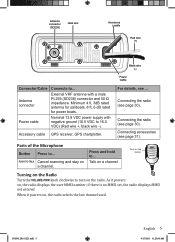
... DC Black wire (-) Power Cable Connector/Cable Antenna connector Power cable Connects to 16.0 VDC) (Red wire +, black wire -). External VHF antenna with negative ground (10.5 VDC to ... Accessory cable GPS receiver, GPS chartplotter. Connecting accessories (see ... Nominal 13.8 VDC power supply with a male PL259 (SO238) connector and 50 Ω impedance. For details, see page 31). Connecting the radio (see page 30). PUSH-TO-TALK Cancel scanning and stay on a channel. UM380_20101221.indd 5 English 5 4/13/2011 11:25:08 AM Parts of the Microphone Button...
... DC Black wire (-) Power Cable Connector/Cable Antenna connector Power cable Connects to 16.0 VDC) (Red wire +, black wire -). External VHF antenna with negative ground (10.5 VDC to ... Accessory cable GPS receiver, GPS chartplotter. Connecting accessories (see ... Nominal 13.8 VDC power supply with a male PL259 (SO238) connector and 50 Ω impedance. For details, see page 31). Connecting the radio (see page 30). PUSH-TO-TALK Cancel scanning and stay on a channel. UM380_20101221.indd 5 English 5 4/13/2011 11:25:08 AM Parts of the Microphone Button...
English Owners Manual
Page 10
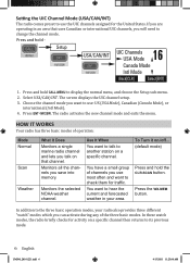
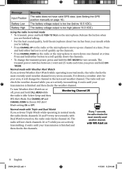
... of operation: Mode Normal Scan Weather What It Does Monitors a single marine radio channel and lets you want to talk to use the UIC channels assigned for the United States. In addition to the three basic operation modes, your area. The screen displays the UIC channel setup. 3. The radio activates the new channel mode and exits the menu. To Turn it on a specific channel then returns to check them for activity on ./off... (default mode) Press...
... of operation: Mode Normal Scan Weather What It Does Monitors a single marine radio channel and lets you want to talk to use the UIC channels assigned for the United States. In addition to the three basic operation modes, your area. The screen displays the UIC channel setup. 3. The radio activates the new channel mode and exits the menu. To Turn it on a specific channel then returns to check them for activity on ./off... (default mode) Press...

English Owners Manual
Page 11
... the same time): Transmit power (1 W or 25 W) Current channel is underway. maintain a watch on Channel mode (USA, CANadian, or INTernational) 25 25 Watts USA Memory Alert GPS Data OK Marine Operator Status Icons Current channel number Current channel name (if the name is too long, the name line scrolls) Message GPS Data OK Check GPS Meaning The radio is not receiving valid GPS data: check the GPS status screen and the GPS connection.
... the same time): Transmit power (1 W or 25 W) Current channel is underway. maintain a watch on Channel mode (USA, CANadian, or INTernational) 25 25 Watts USA Memory Alert GPS Data OK Marine Operator Status Icons Current channel number Current channel name (if the name is too long, the name line scrolls) Message GPS Data OK Check GPS Meaning The radio is not receiving valid GPS data: check the GPS status screen and the GPS connection.
English Owners Manual
Page 12
... either button to scroll quickly down one channel at a time. The radio will change the transmit power, press and hold either button to scroll quickly up one channel at a time. it detects a weather alert for two seconds. Select Setup and then WX Alert Mode. it will not check the weather channel while you are actively transmitting; Use CHANNEL UP and CHANNEL DOWN to move up the channels. Battery High The battery voltage output...
... either button to scroll quickly down one channel at a time. The radio will change the transmit power, press and hold either button to scroll quickly up one channel at a time. it detects a weather alert for two seconds. Select Setup and then WX Alert Mode. it will not check the weather channel while you are actively transmitting; Use CHANNEL UP and CHANNEL DOWN to move up the channels. Battery High The battery voltage output...

English Owners Manual
Page 15
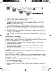
... scheduled time. If you have no FIPS codes programmed into your radio (see page 15). Scan mode with the FCC, NOAA also uses the weather channels to alert you of other hazards besides weather (child abduction alerts, nuclear, biological, etc.). If you don't need Weather Alert Watch to 09 16 then scans the next the next channel. In weather mode, the display shows the following: Weather mode is on Flashing...
... scheduled time. If you have no FIPS codes programmed into your radio (see page 15). Scan mode with the FCC, NOAA also uses the weather channels to alert you of other hazards besides weather (child abduction alerts, nuclear, biological, etc.). If you don't need Weather Alert Watch to 09 16 then scans the next the next channel. In weather mode, the display shows the following: Weather mode is on Flashing...

English Owners Manual
Page 18
... seconds. Your radio comes set to 1 Watt so that there is all you are not making an emergency transmission. The display shows 25 Watts in weather mode or scan mode. If you find yourself far away from other stations. ##NOTE: By default, when you may need . xx See the channel lists beginning on page 37 for two seconds. Select Setup and then Dual...
... seconds. Your radio comes set to 1 Watt so that there is all you are not making an emergency transmission. The display shows 25 Watts in weather mode or scan mode. If you find yourself far away from other stations. ##NOTE: By default, when you may need . xx See the channel lists beginning on page 37 for two seconds. Select Setup and then Dual...
English Owners Manual
Page 20
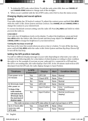
... radio depending on . When you turn the radio on what condition the radio is idle. Select System and then Key Beep. Changing display and sound options Contrast Your radio display has 10 levels of the six digits. 8. Select System and then Lamp Adjust. Choose Off to close the menu screen. Lamp adjust Your radio has 10 brightness levels on ##Note: If the Yes Input Position Yes Error * (continuous display) radio receives GPS data...
... radio depending on . When you turn the radio on what condition the radio is idle. Select System and then Key Beep. Changing display and sound options Contrast Your radio display has 10 levels of the six digits. 8. Select System and then Lamp Adjust. Choose Off to close the menu screen. Lamp adjust Your radio has 10 brightness levels on ##Note: If the Yes Input Position Yes Error * (continuous display) radio receives GPS data...
English Owners Manual
Page 21
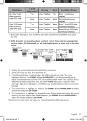
... GPS manual input screen displays; As you update each of the values in turn . continuous display) Normal (Lost GPS data; Setup Use the up and down arrows to adjust each value, the cursor moves to the next value in turn. Display the normal menu and choose the Setup sub-menu. 2. At each of the values GPS Setup in turn . continuous display) * If the radio displays an error condition, the radio cannot receive valid GPS data; Position Set 16 --/-- 11:22U ---o --.- Use CHANNEL...
... GPS manual input screen displays; As you update each of the values in turn . continuous display) Normal (Lost GPS data; Setup Use the up and down arrows to adjust each value, the cursor moves to the next value in turn. Display the normal menu and choose the Setup sub-menu. 2. At each of the values GPS Setup in turn . continuous display) * If the radio displays an error condition, the radio cannot receive valid GPS data; Position Set 16 --/-- 11:22U ---o --.- Use CHANNEL...

English Owners Manual
Page 22
... problems of 20 names and MMSI identification codes for use DSC features, you would call a phone number. Using Digital Selective Calling (DSC) Features What is an MMSI number? Broadcast to all vessels within an "Unavailable" status. Automatically respond to all DSC calls within range (used for automated distress calls. In order to talk on data from your GPS receiver. To call , both radios automatically switch...
... problems of 20 names and MMSI identification codes for use DSC features, you would call a phone number. Using Digital Selective Calling (DSC) Features What is an MMSI number? Broadcast to all vessels within an "Unavailable" status. Automatically respond to all DSC calls within range (used for automated distress calls. In order to talk on data from your GPS receiver. To call , both radios automatically switch...

English Owners Manual
Page 29
..., time, nature code. Pos Send MMSI (or name), position, time, category code, 6. The radio displays the names listed in your previous mode. Group MMSI (or name), category code, communication channel number. Press CLR-SCAN button to exit the detail screen and return to choose the directory entry you should use for each region are available online at the bottom of the display. From the call to a coastal station...
..., time, nature code. Pos Send MMSI (or name), position, time, category code, 6. The radio displays the names listed in your previous mode. Group MMSI (or name), category code, communication channel number. Press CLR-SCAN button to exit the detail screen and return to choose the directory entry you should use for each region are available online at the bottom of the display. From the call to a coastal station...

English Owners Manual
Page 34
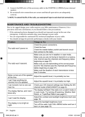
... installed a minimum of your radio. Connect the RED wire of the power cable to the POSITIVE (+) side of the radio, Red wire (+) use waterproof tape to seal electrical connections. 4. See Antenna Selection and Installation on the back of 3 feet from any occupied location; Connecting the radio To operate correctly, your radio requires two electrical connections: xx providing it with power from the boat's electrical system xx connecting a VHF-FM marine antenna to the antenna connector Power Supply Requirements VHF Antenna...
... installed a minimum of your radio. Connect the RED wire of the power cable to the POSITIVE (+) side of the radio, Red wire (+) use waterproof tape to seal electrical connections. 4. See Antenna Selection and Installation on the back of 3 feet from any occupied location; Connecting the radio To operate correctly, your radio requires two electrical connections: xx providing it with power from the boat's electrical system xx connecting a VHF-FM marine antenna to the antenna connector Power Supply Requirements VHF Antenna...
English Owners Manual
Page 36
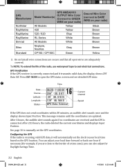
... radio) Black Brown Brown Brown Brown Brown Yellow 3. You can also adjust for example, if you are received and the GPS is correctly connected and it will automatically set the GPS coordinates. GPS Manufacturer Northstar RayMarine RayMarine RayMarine Simrad Sitex Standard GPS NMEA0183 Model Number(s) OUTPUT Wire Color (Connect to GREEN WIRE on the GPS location. Press ENT-1W25W to BARE WIRE on your local time based on your radio...
... radio) Black Brown Brown Brown Brown Brown Yellow 3. You can also adjust for example, if you are received and the GPS is correctly connected and it will automatically set the GPS coordinates. GPS Manufacturer Northstar RayMarine RayMarine RayMarine Simrad Sitex Standard GPS NMEA0183 Model Number(s) OUTPUT Wire Color (Connect to GREEN WIRE on the GPS location. Press ENT-1W25W to BARE WIRE on your local time based on your radio...
English Owners Manual
Page 37
... connections. Your radio supports an external speaker with the following specifications: xx Minimum impedance of 4 Ohms xx Minimum power handling of your external speaker. Display the normal menu and choose the Setup sub-menu. 2. The display shows your local area observes Daylight Savings Time, choose Daylight Save and press the ENT-1W/25W button. 6. Connect the YELLOW wire of the accessory cable to the GROUND WIRE of your chartplotter's NMEA data INPUT 3. Connect the BLACK wire...
... connections. Your radio supports an external speaker with the following specifications: xx Minimum impedance of 4 Ohms xx Minimum power handling of your external speaker. Display the normal menu and choose the Setup sub-menu. 2. The display shows your local area observes Daylight Savings Time, choose Daylight Save and press the ENT-1W/25W button. 6. Connect the YELLOW wire of the accessory cable to the GROUND WIRE of your chartplotter's NMEA data INPUT 3. Connect the BLACK wire...
English Owners Manual
Page 38
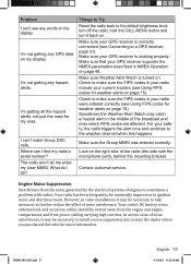
... channels and frequency tables beginning on . Check the power connections. hold CALL-MENU button and turn it is probably too low. Be certain all wire connections are secure and that connect to the POSITIVE (+) WIRE of each transmission is in a watch mode or in weather or scan mode. it is too bright at the correct power level for continued FCC technical compliance of the accessory cable to the radio. channel mode...
... channels and frequency tables beginning on . Check the power connections. hold CALL-MENU button and turn it is probably too low. Be certain all wire connections are secure and that connect to the POSITIVE (+) WIRE of each transmission is in a watch mode or in weather or scan mode. it is too bright at the correct power level for continued FCC technical compliance of the accessory cable to the radio. channel mode...
English Owners Manual
Page 39
... weather alerts on page 46. I find my radio's serial number? Engine Noise Suppression Interference from power cabling carrying high currents. hold the CALL-MENU button and turn off the radio; However, in your radio include your radio were entered correctly (see Connecting to make sure the FIPS codes in the middle of the radio (the side with radios. I do? Things to Try Reset the radio back to the default...
... weather alerts on page 46. I find my radio's serial number? Engine Noise Suppression Interference from power cabling carrying high currents. hold the CALL-MENU button and turn off the radio; However, in your radio include your radio were entered correctly (see Connecting to make sure the FIPS codes in the middle of the radio (the side with radios. I do? Things to Try Reset the radio back to the default...
English Owners Manual
Page 40
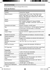
...:18 AM Radio Specifications General Controls Status Indicators Display Buttons Connectors and Cables Size Weight Supply Voltage Standard Accessories Antenna Impedance Microphone Speaker Operating Temperature Range Shock and Vibration FCC Approvals Transmitter Power Output Power Requirement Modulation Hum and Noise Signal-toNoise Audio Distortion Spurious Suppression Output Power Stabilization 36 English Volume-Pwr, Squelch Transmit power, Scan mode, Triple Watch mode, Battery High, Battery low, USA, CAN, INT, Alert, Memory, GPS, Message, Weather band, GPS status and Channel Display LCD (Full...
...:18 AM Radio Specifications General Controls Status Indicators Display Buttons Connectors and Cables Size Weight Supply Voltage Standard Accessories Antenna Impedance Microphone Speaker Operating Temperature Range Shock and Vibration FCC Approvals Transmitter Power Output Power Requirement Modulation Hum and Noise Signal-toNoise Audio Distortion Spurious Suppression Output Power Stabilization 36 English Volume-Pwr, Squelch Transmit power, Scan mode, Triple Watch mode, Battery High, Battery low, USA, CAN, INT, Alert, Memory, GPS, Message, Weather band, GPS status and Channel Display LCD (Full...
English Owners Manual
Page 50
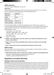
... NMEA Input If you are received, the radio displays latitude/longitude, date, time, course, and speed. This transmitter will operate on page 37 for exclusive use in Canada, and use , see the FCC maritime radio page at the FCC website (http:// wireless.fcc.gov/marine/) or contact the FCC Call Center at 1-888-CALLFCC. It should be set to check whether the GPS data is...
... NMEA Input If you are received, the radio displays latitude/longitude, date, time, course, and speed. This transmitter will operate on page 37 for exclusive use in Canada, and use , see the FCC maritime radio page at the FCC website (http:// wireless.fcc.gov/marine/) or contact the FCC Call Center at 1-888-CALLFCC. It should be set to check whether the GPS data is...


