
Users Manual Canada; English
Page 4
... M9 System Auto Off 6-13 Chapter 7 HW Setup & BIOS Setup Accessing HW Setup 7-1 HW Setup window 7-1 BIOS Setup Program 7-8 Chapter 8 Troubleshooting Problem solving process 8-1 Hardware and system checklist 8-3 TOSHIBA support 8-21 Appendix A Specifications Physical Dimensions A-1 Environmental Requirements A-1 Appendix B Display Controller and Video mode Display controller B-1 Video mode B-1 Appendix C AT Commands Appendix D S-registers S-register values D-1 AT command set result codes D-5 Appendix E V.90 V.90 mode E-1 AT Command E-3 Appendix F Wireless LAN Card...
... M9 System Auto Off 6-13 Chapter 7 HW Setup & BIOS Setup Accessing HW Setup 7-1 HW Setup window 7-1 BIOS Setup Program 7-8 Chapter 8 Troubleshooting Problem solving process 8-1 Hardware and system checklist 8-3 TOSHIBA support 8-21 Appendix A Specifications Physical Dimensions A-1 Environmental Requirements A-1 Appendix B Display Controller and Video mode Display controller B-1 Video mode B-1 Appendix C AT Commands Appendix D S-registers S-register values D-1 AT command set result codes D-5 Appendix E V.90 V.90 mode E-1 AT Command E-3 Appendix F Wireless LAN Card...
Users Manual Canada; English
Page 6
... for accuracy. User's Manual vi TOSHIBA TECRA M9 Portable Personal Computer User's Manual First edition June 2007 Copyright authority for personal use or use of TOSHIBA. Copyrighted material can be reproduced in any reproduction from errors, omissions or discrepancies between the computer and the manual. Disclaimer This manual has been validated and reviewed for damages incurred directly or indirectly from this manual. The instructions and descriptions...
... for accuracy. User's Manual vi TOSHIBA TECRA M9 Portable Personal Computer User's Manual First edition June 2007 Copyright authority for personal use or use of TOSHIBA. Copyrighted material can be reproduced in any reproduction from errors, omissions or discrepancies between the computer and the manual. Disclaimer This manual has been validated and reviewed for damages incurred directly or indirectly from this manual. The instructions and descriptions...

Users Manual Canada; English
Page 11
... you are ever needed on your modem from your fax software before sending messages. Fax branding The Telephone Consumer Protection Act of 1991 makes it is not feasible, you will notify you with the FCC. When you to make changes in writing to ...the opportunity to correct the problem and informed of your right to do this change. User's Manual xi TECRA M9 Telephone company procedures The goal of TOSHIBA Corporation. In order to file a complaint with the best service it may temporarily discontinue service. In the event repairs are notified, you will...
... you are ever needed on your modem from your fax software before sending messages. Fax branding The Telephone Consumer Protection Act of 1991 makes it is not feasible, you will notify you with the FCC. When you to make changes in writing to ...the opportunity to correct the problem and informed of your right to do this change. User's Manual xi TECRA M9 Telephone company procedures The goal of TOSHIBA Corporation. In order to file a complaint with the best service it may temporarily discontinue service. In the event repairs are notified, you will...
Users Manual Canada; English
Page 13
... customers. Failure to operate should not be used in any manner which displays the currently active setting. e.g., accessing the Internet requires suitable software in addition to the Australian PSTN would be no permit in force for this device in New Zealand ■ The grant of a Telepermit for a device in no way indicates Telecom acceptance of responsibility for the connection of the call and...
... customers. Failure to operate should not be used in any manner which displays the currently active setting. e.g., accessing the Internet requires suitable software in addition to the Australian PSTN would be no permit in force for this device in New Zealand ■ The grant of a Telepermit for a device in no way indicates Telecom acceptance of responsibility for the connection of the call and...
Users Manual Canada; English
Page 17
... with this manual by -step instructions on setting up and begin using optional devices and troubleshooting. Conventions This manual uses the following their definition. Acronyms are enclosed in parentheses following formats to setup and configure these features. User's Manual xvii If you are uncommon or unique to this manual is designed to set up your computer, basic operations and care, using your TECRA M9 computer. For example: Read Only Memory (ROM). Abbreviations...
... with this manual by -step instructions on setting up and begin using optional devices and troubleshooting. Conventions This manual uses the following their definition. Acronyms are enclosed in parentheses following formats to setup and configure these features. User's Manual xvii If you are uncommon or unique to this manual is designed to set up your computer, basic operations and care, using your TECRA M9 computer. For example: Read Only Memory (ROM). Abbreviations...
Users Manual Canada; English
Page 36
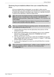
... Boot Priority section in when you originally received it. You can setup the respective drivers / utilities from the menu. While holding down F12 key on -screen instructions. A menu will be lost. 1. C:\TOSAPINS\*** User's Manual 1-15 To perform this to allow sounds to be displayed from your computer when the In Touch with Tomorrow TOSHIBA logo screen appears, release the F12 key. 3. When you reinstall the Windows operating system, the hard disk...
... Boot Priority section in when you originally received it. You can setup the respective drivers / utilities from the menu. While holding down F12 key on -screen instructions. A menu will be lost. 1. C:\TOSAPINS\*** User's Manual 1-15 To perform this to allow sounds to be displayed from your computer when the In Touch with Tomorrow TOSHIBA logo screen appears, release the F12 key. 3. When you reinstall the Windows operating system, the hard disk...

Users Manual Canada; English
Page 45
.... User's Manual 2-9 Refer to Chapter 5, The Keyboard, for details. The keyboard is connected will open the Windows VistaTM TMM (Transient Multimon Manager) screen. When power-off . Pressing this button to turn the computer's power on -screen pointer. TOSHIBA Assist button TOSHIBA Presentation button Fingerprint Sensor Press this button to Chapter 4, Using the Fingerprint Sensor. For detailed information on -screen pointer. A pointer control device located in Chapter 4, Operating Basics. The internal keyboard provides the embedded numeric overlay keys, dedicated...
.... User's Manual 2-9 Refer to Chapter 5, The Keyboard, for details. The keyboard is connected will open the Windows VistaTM TMM (Transient Multimon Manager) screen. When power-off . Pressing this button to turn the computer's power on -screen pointer. TOSHIBA Assist button TOSHIBA Presentation button Fingerprint Sensor Press this button to Chapter 4, Using the Fingerprint Sensor. For detailed information on -screen pointer. A pointer control device located in Chapter 4, Operating Basics. The internal keyboard provides the embedded numeric overlay keys, dedicated...
Users Manual Canada; English
Page 56
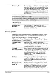
... a DVD Super Multi drive and secondary hard disk drive. Legal Footnote (Wireless LAN)*8 For more convenient to start the computer and launch the program. Special features The following procedures. *1 To access the Power Options, click Start -> Control Panel -> System and Maintenance -> Power Options. When power-off power to the Legal Footnotes section in Appendix K or click the *8 above. TOSHIBA Assist button Press this button when an external display is pressed. Hot keys Hot keys are advanced features which make...
... a DVD Super Multi drive and secondary hard disk drive. Legal Footnote (Wireless LAN)*8 For more convenient to start the computer and launch the program. Special features The following procedures. *1 To access the Power Options, click Start -> Control Panel -> System and Maintenance -> Power Options. When power-off power to the Legal Footnotes section in Appendix K or click the *8 above. TOSHIBA Assist button Press this button when an external display is pressed. Hot keys Hot keys are advanced features which make...
Users Manual Canada; English
Page 69
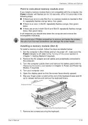
.... 5. Installing a memory module (Slot A) To install a memory module, follow the steps as detailed below: 1. Remove the AC adaptor and all instances you install a memory module that the screen faces directly upward. 6. User's Manual 3-18 Hardware, Utilities and Options Point to note about memory module error If you should shut down and remove the battery pack (refer to Replacing the battery pack section in Chapter 6, Power and Power-Up Modes, if required). 4. In all cables and peripherals connected to remove and...
.... 5. Installing a memory module (Slot A) To install a memory module, follow the steps as detailed below: 1. Remove the AC adaptor and all instances you install a memory module that the screen faces directly upward. 6. User's Manual 3-18 Hardware, Utilities and Options Point to note about memory module error If you should shut down and remove the battery pack (refer to Replacing the battery pack section in Chapter 6, Power and Power-Up Modes, if required). 4. In all cables and peripherals connected to remove and...
Users Manual Canada; English
Page 73
.... 6. make sure the Power indicator is installed, use the computer for main memory. Grasp the sides of them . Set the computer to Boot Mode and turn its power off the power section in Chapter 1, Getting Started if required). 2. Remove the AC adaptor and all cables and peripherals connected to release the memory module. To remove the memory module, follow the steps as described in the previous section. 8. Turn your computer over. Use the slot...
.... 6. make sure the Power indicator is installed, use the computer for main memory. Grasp the sides of them . Set the computer to Boot Mode and turn its power off the power section in Chapter 1, Getting Started if required). 2. Remove the AC adaptor and all cables and peripherals connected to release the memory module. To remove the memory module, follow the steps as described in the previous section. 8. Turn your computer over. Use the slot...

Users Manual Canada; English
Page 75
... Chapter 6, Power and Power-Up Modes, if required. 9. Please also ensure that the memory module cover is recognized - Remove the AC adaptor and all cables and peripherals connected to Boot Mode and turn its left and right hand edges - Install the battery pack - refer to Replacing the battery pack section in serious injury. ■ Do not touch the connectors on the memory module or on and make sure the Power indicator is...
... Chapter 6, Power and Power-Up Modes, if required. 9. Please also ensure that the memory module cover is recognized - Remove the AC adaptor and all cables and peripherals connected to Boot Mode and turn its left and right hand edges - Install the battery pack - refer to Replacing the battery pack section in serious injury. ■ Do not touch the connectors on the memory module or on and make sure the Power indicator is...

Users Manual Canada; English
Page 76
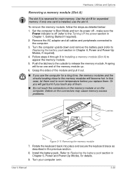
.... Hardware, Utilities and Options 3. Install the battery pack - User's Manual 3-25 Push the latches away from the computer. ■ If you replace them . ■ Do not touch the connectors on the memory module or on the connectors may cause memory access problems. Latches Figure 3-15 Removing the memory module 8. refer to Replacing the battery pack section in order to the cover in place and secure it - please note that the memory module cover is...
.... Hardware, Utilities and Options 3. Install the battery pack - User's Manual 3-25 Push the latches away from the computer. ■ If you replace them . ■ Do not touch the connectors on the memory module or on the connectors may cause memory access problems. Latches Figure 3-15 Removing the memory module 8. refer to Replacing the battery pack section in order to the cover in place and secure it - please note that the memory module cover is...
Users Manual Canada; English
Page 136
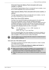
... change the Real Time Clock settings by turning the computer on the power: S **** RTC battery is low or CMOS checksum is inconsistent **** Press [F1] key to the enclosed Instruction Manual for Safety and Comfort for further information. User's Manual 6-4 Real Time Clock (RTC) battery The Real Time Clock (RTC) battery provides power for the internal real time clock and calendar function and also maintains the system configuration...
... change the Real Time Clock settings by turning the computer on the power: S **** RTC battery is low or CMOS checksum is inconsistent **** Press [F1] key to the enclosed Instruction Manual for Safety and Comfort for further information. User's Manual 6-4 Real Time Clock (RTC) battery The Real Time Clock (RTC) battery provides power for the internal real time clock and calendar function and also maintains the system configuration...
Users Manual Canada; English
Page 159
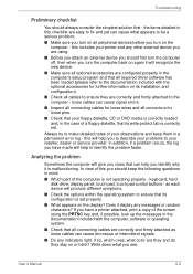
... the new device. ■ Make sure all optional accessories are configured properly in the computer's setup program and that all cables to ensure they are they and do they stay on the computer - the items detailed in the documentation included with the optional accessories for loose pins. ■ Check that its write protect tab is set . keyboard, hard disk drive, display panel, touch pad, touch pad control buttons - as loose cables can...
... the new device. ■ Make sure all optional accessories are configured properly in the computer's setup program and that all cables to ensure they are they and do they stay on the computer - the items detailed in the documentation included with the optional accessories for loose pins. ■ Check that its write protect tab is set . keyboard, hard disk drive, display panel, touch pad, touch pad control buttons - as loose cables can...

Users Manual Canada; English
Page 160
... following areas: ■ System start-up ■ Self test ■ Power ■ Password ■ Keyboard ■ Internal display panel ■ Hard disk drive ■ DVD Super Multi drive ■ USB floppy diskette drive ■ PC Card ■ SD/SDHC Card ■ Dual Pointing Device ■ Fingerprint Sensor ■ USB device ■ Additional memory module ■ Sound system ■ External monitor ■ i.LINK (IEEE1394) device ■ Modem ■ LAN ■ Wireless LAN ■ Bluetooth ■ Recovery Discs User's Manual 8-3 Basic problems may be damaged or...
... following areas: ■ System start-up ■ Self test ■ Power ■ Password ■ Keyboard ■ Internal display panel ■ Hard disk drive ■ DVD Super Multi drive ■ USB floppy diskette drive ■ PC Card ■ SD/SDHC Card ■ Dual Pointing Device ■ Fingerprint Sensor ■ USB device ■ Additional memory module ■ Sound system ■ External monitor ■ i.LINK (IEEE1394) device ■ Modem ■ LAN ■ Wireless LAN ■ Bluetooth ■ Recovery Discs User's Manual 8-3 Basic problems may be damaged or...
Users Manual Canada; English
Page 164
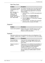
... load. Keyboard Keyboard problems can be displayed. 5. press the FN + F11 hot key and try typing again. Please refer to your reseller, dealer or service provider. User's Manual 8-7 Password Problem Procedure Cannot enter password Please refer to set Date/Time. 3. you are still unable to set the date and screen: time in Chapter 6, Power and Power-Up Modes for further information. inconsistent. 2. Set the date in the System Time field. 4. Troubleshooting Real...
... load. Keyboard Keyboard problems can be displayed. 5. press the FN + F11 hot key and try typing again. Please refer to your reseller, dealer or service provider. User's Manual 8-7 Password Problem Procedure Cannot enter password Please refer to set Date/Time. 3. you are still unable to set the date and screen: time in Chapter 6, Power and Power-Up Modes for further information. inconsistent. 2. Set the date in the System Time field. 4. Troubleshooting Real...
Users Manual Canada; English
Page 174
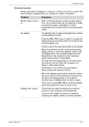
... display panel and external monitor to clone mode. Problem Procedure Monitor does not turn off by the timer, the display panel or the external monitor may not display when turned on the external monitor. Check to resolve the problem, contact your monitor for the internal display only. When the external monitor is connected. User's Manual 8-17 Troubleshooting External monitor Please also refer to Chapter 3, Hardware, Utilities and Options, and to the documentation supplied with your reseller, dealer or service provider. When the display panel...
... display panel and external monitor to clone mode. Problem Procedure Monitor does not turn off by the timer, the display panel or the external monitor may not display when turned on the external monitor. Check to resolve the problem, contact your monitor for the internal display only. When the external monitor is connected. User's Manual 8-17 Troubleshooting External monitor Please also refer to Chapter 3, Hardware, Utilities and Options, and to the documentation supplied with your reseller, dealer or service provider. When the display panel...
Users Manual Canada; English
Page 232
... extend to change the hardware characteristics by manually pressing marked keys. For each key, the transmitted code is, in turn, representative of a circuit. See also byte and megabyte. See also hertz. keyboard: An input device containing switches that equals 1 million cycles per second. Each keystroke activates a switch that emits light when a current is etched into character forming segments with leads that uses large scale...
... extend to change the hardware characteristics by manually pressing marked keys. For each key, the transmitted code is, in turn, representative of a circuit. See also byte and megabyte. See also hertz. keyboard: An input device containing switches that equals 1 million cycles per second. Each keystroke activates a switch that emits light when a current is etched into character forming segments with leads that uses large scale...
Users Manual Canada; English
Page 239
...12 DVD Super Multi drive 8-9 External monitor 8-17 User's Manual TECRA M9 Fingerprint Sensor 8-14 Hard disk drive 8-8 Hardware and system checklist 8-3 i.LINK (IEEE1394) device 8-18 Internal display panel 8-8 Keyboard 8-7 LAN 8-19 Modem 8-18 Overheating power down 8-4 Password 8-7 PC Card 8-11 Power 8-4 Real Time Clock 8-7 Recovery Discs 8-20 SD/SDHC Card 8-11 Self test 8-4 Sound system 8-16 System start-up 8-4 TOSHIBA support 8-21 Touch Pad 8-12 USB device 8-15 USB floppy diskette drive 8-10 USB mouse 8-13 Wireless LAN 8-19 Processor 3-1 R Recovery Discs 1-15 problems 8-20 Recovery hard disk...
...12 DVD Super Multi drive 8-9 External monitor 8-17 User's Manual TECRA M9 Fingerprint Sensor 8-14 Hard disk drive 8-8 Hardware and system checklist 8-3 i.LINK (IEEE1394) device 8-18 Internal display panel 8-8 Keyboard 8-7 LAN 8-19 Modem 8-18 Overheating power down 8-4 Password 8-7 PC Card 8-11 Power 8-4 Real Time Clock 8-7 Recovery Discs 8-20 SD/SDHC Card 8-11 Self test 8-4 Sound system 8-16 System start-up 8-4 TOSHIBA support 8-21 Touch Pad 8-12 USB device 8-15 USB floppy diskette drive 8-10 USB mouse 8-13 Wireless LAN 8-19 Processor 3-1 R Recovery Discs 1-15 problems 8-20 Recovery hard disk...
Detailed Specs for Tecra M9 PTM91C-TG709C English
Page 1
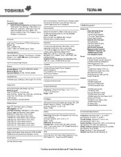
... TOSHIBA Bluetooth® Stack Optimize TOSHIBA Zooming Utility LCD Rotation Utility One-touch Resolution Change TOSHIBA Power Saver Utility TOSHIBA Optical Disc Drive Power On/Off Wireless On/Off Switch TOSHIBA Fn-esse Shortcut Utility TOSHIBA Mouse Utility FN Shortcut Keys Windows® Mobility Center Button Environmental Specifications Temperature: Operating 5°to 35°C (41° to select English or French operating system HDD Pre-installed Image Recovery Memory Standard Memory: 2x1GB PC2-5300 DDR2, 667MHz Maximum Memory: 4GB Expansion Modules: 512MB, 1024MB, 2048MB Hard Disk...
... TOSHIBA Bluetooth® Stack Optimize TOSHIBA Zooming Utility LCD Rotation Utility One-touch Resolution Change TOSHIBA Power Saver Utility TOSHIBA Optical Disc Drive Power On/Off Wireless On/Off Switch TOSHIBA Fn-esse Shortcut Utility TOSHIBA Mouse Utility FN Shortcut Keys Windows® Mobility Center Button Environmental Specifications Temperature: Operating 5°to 35°C (41° to select English or French operating system HDD Pre-installed Image Recovery Memory Standard Memory: 2x1GB PC2-5300 DDR2, 667MHz Maximum Memory: 4GB Expansion Modules: 512MB, 1024MB, 2048MB Hard Disk...


