

Replacement Instructions
Page 1
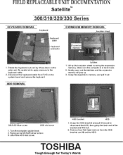
... card lock Eject button PC card PC card slot cover 1. Pull out the eject button next to the PC card you want to release it . Pullthe battery pack slightlyforward and lift out the battery pack. Open the display panel 2. TOSHIBA Tough Enough for Today's World. Slidethe batteryIdch in the direction ofthe arrow KEYBOARD REMOVAL • ANEWl1,611:,111JIA - Slide the PC cad lock to the unlock position. 3. Keyboard Keyboard brace 1. OPTIONAL PCMCIA CARD REMOVAL Battery...
... card lock Eject button PC card PC card slot cover 1. Pull out the eject button next to the PC card you want to release it . Pullthe battery pack slightlyforward and lift out the battery pack. Open the display panel 2. TOSHIBA Tough Enough for Today's World. Slidethe batteryIdch in the direction ofthe arrow KEYBOARD REMOVAL • ANEWl1,611:,111JIA - Slide the PC cad lock to the unlock position. 3. Keyboard Keyboard brace 1. OPTIONAL PCMCIA CARD REMOVAL Battery...
Replacement Instructions
Page 2
.... FIELD REPLACEABLE UNIT DOCUMENTATION Satellites ' 300/310/320/330 Series KEYBOARD REMOVAL Keyboard EXPANSION MEMORY REMOVAL Insulator sheet Keyboard cable • Keyboard connector Expansion memoir, 1 1. HDD REMOVAL Latches 1. Removeone M2.5>25silver screw. 3. Rotatethe keyboardout and lay itface dawn on the system board and remove the keyboard. Disconnectthekeyboardcable from the HDD bracket and lift outthe HDD. Grasp the expansion memory and pull it out 2. M2.5>25;liver screw HDD slot cover 1. Makesurethecomputer's in boot mode...
.... FIELD REPLACEABLE UNIT DOCUMENTATION Satellites ' 300/310/320/330 Series KEYBOARD REMOVAL Keyboard EXPANSION MEMORY REMOVAL Insulator sheet Keyboard cable • Keyboard connector Expansion memoir, 1 1. HDD REMOVAL Latches 1. Removeone M2.5>25silver screw. 3. Rotatethe keyboardout and lay itface dawn on the system board and remove the keyboard. Disconnectthekeyboardcable from the HDD bracket and lift outthe HDD. Grasp the expansion memory and pull it out 2. M2.5>25;liver screw HDD slot cover 1. Makesurethecomputer's in boot mode...

Replacement Instructions
Page 3
... I a • I sr INSULATOR REMOVAL Insulator •I Display assembly I I Latch Pin. Tape., Ill 1. Lift off thetop cover and display assembly in the direction of the arrant RTC & backup battery pad 1. If the insulator S not irstalledthe unit will not power ON. Turn the computer upside down and removetva M2.5>8siker screws fromthe batteryslot one M2.5>8silver screwhomthe HDD slot.fi'e M2.5x25 silver...
... I a • I sr INSULATOR REMOVAL Insulator •I Display assembly I I Latch Pin. Tape., Ill 1. Lift off thetop cover and display assembly in the direction of the arrant RTC & backup battery pad 1. If the insulator S not irstalledthe unit will not power ON. Turn the computer upside down and removetva M2.5>8siker screws fromthe batteryslot one M2.5>8silver screwhomthe HDD slot.fi'e M2.5x25 silver...

Replacement Instructions
Page 4
... lut25x8 brass "screw 1. D's connect the FDD fleAble cable from it case. 4. TOSHIBA Tough Enough tor Today's World. FIELD REPLACEABLE UNIT DOCUMENTATION Satellite 300/310/320/330 Series RTC and BACKUP BATTERY REMOVAL LED BOARD and MEMBRANE WATCH REMOVAL PJ7 Flex, cable Pad] Backiip battery RTC battery 1. Disconnect the backup battery horn PJ802 on the system board. 2. FDD REMOVAL PJ14 e. Remove four flat-headscrews securing the FDD to remove the board. 4. Lift outthe RTC...
... lut25x8 brass "screw 1. D's connect the FDD fleAble cable from it case. 4. TOSHIBA Tough Enough tor Today's World. FIELD REPLACEABLE UNIT DOCUMENTATION Satellite 300/310/320/330 Series RTC and BACKUP BATTERY REMOVAL LED BOARD and MEMBRANE WATCH REMOVAL PJ7 Flex, cable Pad] Backiip battery RTC battery 1. Disconnect the backup battery horn PJ802 on the system board. 2. FDD REMOVAL PJ14 e. Remove four flat-headscrews securing the FDD to remove the board. 4. Lift outthe RTC...

Replacement Instructions
Page 5
... arrow SYSTEM BOARD REMOVAL Latches NOTE: The CD-ROM, flexible cable and bracket are all separate parts. M2543 brass screws M2.5x4 brass serer), P C card eject buttons 1.You will first removethe PC cardslot cover. Pull out the PC card eject buttons and push them in the direction of the connector lever at the same time. do not bendthem. 2. TOSHIBA Tough Enough...
... arrow SYSTEM BOARD REMOVAL Latches NOTE: The CD-ROM, flexible cable and bracket are all separate parts. M2543 brass screws M2.5x4 brass serer), P C card eject buttons 1.You will first removethe PC cardslot cover. Pull out the PC card eject buttons and push them in the direction of the connector lever at the same time. do not bendthem. 2. TOSHIBA Tough Enough...

Replacement Instructions
Page 6
... Right Speakerbrace 1. Remove Tape coveting PJ1 and the fan cable. 2. The cooling fan and system board ate sepatate parts. The fan and two sctevvs should be keptto be attached to TOSHIBA with defective system boards. TOSHIBA Tough Enough for Today's World. FIELD REPLACEABLE UNIT DOCUMENTATION Satellites ' 300/310/320/330 Series COOLING FAN REMOVAL ae REMOVING THE SPEAKERS C. NOTE. Swtem board Tape pm Coo Ing fan 2x I4...
... Right Speakerbrace 1. Remove Tape coveting PJ1 and the fan cable. 2. The cooling fan and system board ate sepatate parts. The fan and two sctevvs should be keptto be attached to TOSHIBA with defective system boards. TOSHIBA Tough Enough for Today's World. FIELD REPLACEABLE UNIT DOCUMENTATION Satellites ' 300/310/320/330 Series COOLING FAN REMOVAL ae REMOVING THE SPEAKERS C. NOTE. Swtem board Tape pm Coo Ing fan 2x I4...

Replacement Instructions
Page 7
...5x8 brass screws thatweie coveted by the seats. 3. FIELD REPLACEABLE UNIT DOCUMENTATION Satellites ' 300/310/320/330 Series DISPLAY MASK Mask seal Display mask seal 1. Catefully invertyou( fingers betweenthe mask and the LCD panel and ply open the snaps. locations " 4.. atthe bottom(2 snaps) and atthe hinges (2 ...exposetwo M2.5x8brass screws seemingthe display mask 2. Stattwithsk snaps amiss the top of 18 snaps secure the display mask. A total of the display mask. ..S41O 41 - -%tT•••h•9ir' a te% .041/4.04 Snap - TOSHIBA Tough Enough for Today's ...
...5x8 brass screws thatweie coveted by the seats. 3. FIELD REPLACEABLE UNIT DOCUMENTATION Satellites ' 300/310/320/330 Series DISPLAY MASK Mask seal Display mask seal 1. Catefully invertyou( fingers betweenthe mask and the LCD panel and ply open the snaps. locations " 4.. atthe bottom(2 snaps) and atthe hinges (2 ...exposetwo M2.5x8brass screws seemingthe display mask 2. Stattwithsk snaps amiss the top of 18 snaps secure the display mask. A total of the display mask. ..S41O 41 - -%tT•••h•9ir' a te% .041/4.04 Snap - TOSHIBA Tough Enough for Today's ...

Replacement Instructions
Page 8
FIELD REPLACEABLE UNIT DOCUMENTATION Satellites ' 300/310/320/330 Series FL INVERTER and SCREEN LCD module M2.5x7 sikerscrens M2 5x7 silver screns HV able M2 5x8 brass screw FL inxerter board M25xt brass serer) Contrast board M2510 Az _ brass soles/ 1. C at efully rotatethe FL inverter board out:ifOM tight to left of the LCD cowr. 7. C at efully rotatethe LCD moduleifOM tight...
FIELD REPLACEABLE UNIT DOCUMENTATION Satellites ' 300/310/320/330 Series FL INVERTER and SCREEN LCD module M2.5x7 sikerscrens M2 5x7 silver screns HV able M2 5x8 brass screw FL inxerter board M25xt brass serer) Contrast board M2510 Az _ brass soles/ 1. C at efully rotatethe FL inverter board out:ifOM tight to left of the LCD cowr. 7. C at efully rotatethe LCD moduleifOM tight...


