

Maintenance Manual
Page 4
The manual is divided into the following : ‰ Handling the LCD module ‰ Board layout ‰ Pin assignments ‰ Keyboard scan/character codes ‰ Key layout ‰ Wiring diagrams ‰ BIOS rewrite procedures ‰ EC/KBC rewrite procedures ‰ Reliability iv [CONFIDENTIAL]... and diagnostic operations for maintenance service. Appendices The appendices describe the following parts: Chapter 1 Hardware Overview describes the T PORTÉGÉ R500. Chapter 4 Replacement Procedures describes the removal and replacement of the FRUs. system unit and each FRU.
The manual is divided into the following : ‰ Handling the LCD module ‰ Board layout ‰ Pin assignments ‰ Keyboard scan/character codes ‰ Key layout ‰ Wiring diagrams ‰ BIOS rewrite procedures ‰ EC/KBC rewrite procedures ‰ Reliability iv [CONFIDENTIAL]... and diagnostic operations for maintenance service. Appendices The appendices describe the following parts: Chapter 1 Hardware Overview describes the T PORTÉGÉ R500. Chapter 4 Replacement Procedures describes the removal and replacement of the FRUs. system unit and each FRU.
Maintenance Manual
Page 8
Chapter 4 Replacement Procedures 4.1 Overview...4-1 4.2 Battery pack ...4-8 4.3 PC card...4-10 4.4 Memory module B 4-11 4.5 HDD...4-13 4.6 Keyboard...4-17 4.7 Memory module A 4-21 4.8 Cover assembly and Base assembly 4-23 4.9 Base latch ...4-26 4.10 Front panel/Microphone 4-27 4.11 Bluetooth module...4-33 4.12 Touch pad...4-...
Chapter 4 Replacement Procedures 4.1 Overview...4-1 4.2 Battery pack ...4-8 4.3 PC card...4-10 4.4 Memory module B 4-11 4.5 HDD...4-13 4.6 Keyboard...4-17 4.7 Memory module A 4-21 4.8 Cover assembly and Base assembly 4-23 4.9 Base latch ...4-26 4.10 Front panel/Microphone 4-27 4.11 Bluetooth module...4-33 4.12 Touch pad...4-...

Maintenance Manual
Page 43
...in the LCD Check 2-6 Procedure 2 Error Code Check 2-7 Procedure 3 Connection Check 2-12 Procedure 4 Charge Check 2-13 Procedure 5 Replacement Check 2-14 2.4 System Board Troubleshooting 2-15 Procedure 1 Message Check 2-16 Procedure 2 Serial Port Check (Boot Mode 2-18 Procedure ...Program Execution Check 2-38 Procedure 5 Connector Check and Replacement Check 2-39 2.7 Keyboard and Dual point Troubleshooting 2-40 Procedure 1 Diagnostic Test Program Execution Check 2-40 Procedure 2 Connector Check and Replacement Check 2-41 PORTEGE R500 Maintenance Manual (960-634) [CONFIDENTIAL] 2-iii
...in the LCD Check 2-6 Procedure 2 Error Code Check 2-7 Procedure 3 Connection Check 2-12 Procedure 4 Charge Check 2-13 Procedure 5 Replacement Check 2-14 2.4 System Board Troubleshooting 2-15 Procedure 1 Message Check 2-16 Procedure 2 Serial Port Check (Boot Mode 2-18 Procedure ...Program Execution Check 2-38 Procedure 5 Connector Check and Replacement Check 2-39 2.7 Keyboard and Dual point Troubleshooting 2-40 Procedure 1 Diagnostic Test Program Execution Check 2-40 Procedure 2 Connector Check and Replacement Check 2-41 PORTEGE R500 Maintenance Manual (960-634) [CONFIDENTIAL] 2-iii
Maintenance Manual
Page 47
Keyboard/Dual point 6. Display 7. Modem 9. Fingerprint sensor . Detailed Replacement Procedures are described in Chapter 3. For tools required for ... Wireless LAN 12. 2.1 Troubleshooting 2 Troubleshooting Procedures 2 2.1 Troubleshooting Chapter 2 describes how to determine if a Field Replaceable Unit (FRU) in the computer is causing the computer to the Chapter3. The FRUs covered are necessary for implementing ...An external microphone(for Sound trouble shooting) PORTEGE R500 Maintenance Manual (960-634) [CONFIDENTIAL] 2-1 Headphone(for Sound trouble shooting) 7.
Keyboard/Dual point 6. Display 7. Modem 9. Fingerprint sensor . Detailed Replacement Procedures are described in Chapter 3. For tools required for ... Wireless LAN 12. 2.1 Troubleshooting 2 Troubleshooting Procedures 2 2.1 Troubleshooting Chapter 2 describes how to determine if a Field Replaceable Unit (FRU) in the computer is causing the computer to the Chapter3. The FRUs covered are necessary for implementing ...An external microphone(for Sound trouble shooting) PORTEGE R500 Maintenance Manual (960-634) [CONFIDENTIAL] 2-1 Headphone(for Sound trouble shooting) 7.

Maintenance Manual
Page 86
...2: Connector Check and Replacement Check Procedure 1 Diagnostic Test Program Execution Check Execute the Keyboard Test in the Diagnostic Program. If an error does not occur, the keyboard is functioning properly, ...perform the following procedures. Start with Procedure 1 and continue with the other procedures as instructed. 2 Troubleshooting Procedures 2.7 Keyboard and Dual point Troubleshooting 2.7 Keyboard and Dual point Troubleshooting To determine if the computer's keyboard or touch pad is functioning properly. 2-40 [CONFIDENTIAL] PORTEGE R500...
...2: Connector Check and Replacement Check Procedure 1 Diagnostic Test Program Execution Check Execute the Keyboard Test in the Diagnostic Program. If an error does not occur, the keyboard is functioning properly, ...perform the following procedures. Start with Procedure 1 and continue with the other procedures as instructed. 2 Troubleshooting Procedures 2.7 Keyboard and Dual point Troubleshooting 2.7 Keyboard and Dual point Troubleshooting To determine if the computer's keyboard or touch pad is functioning properly. 2-40 [CONFIDENTIAL] PORTEGE R500...

Maintenance Manual
Page 87
... sure the keyboard cable is still an error, go to CN3230 on the system board. Replace it with Check 1. 2. If the touch pad malfunctions, start with a new one following checks: 1. Replace it with Check 3. If the problem still exists, perform Check 5. If there is still an error, go to Procedure 1. PORTEGE R500 Maintenance Manual (960...
... sure the keyboard cable is still an error, go to CN3230 on the system board. Replace it with Check 1. 2. If the touch pad malfunctions, start with a new one following checks: 1. Replace it with Check 3. If the problem still exists, perform Check 5. If there is still an error, go to Procedure 1. PORTEGE R500 Maintenance Manual (960...
Maintenance Manual
Page 213
4 Replacement Procedures Chapter 4 Contents 4.1 General...4-1 4.2 Battery pack ...4-8 4.3 PC card...4-10 4.4 SD memory card ...4-11 4.5 Memory module...4-12 4.6 Base cover assembly 4-15 4.7 PC card slot ...4-18 4.8 Battery ... 4.17 USB board/Switch unit 4-42 4.18 System board...4-45 4.19 Speaker...4-48 4.20 Display portion ...4-50 4.21 Touch pad/Fingerprint sensor board 4-54 4.22 Keyboard...4-57 4.23 LCD unit ...4-59 4.24 Wireless LAN antenna/Bluetooth antenna 4-62 4.25 Hinge...4-64 PORTÉGÉ...
4 Replacement Procedures Chapter 4 Contents 4.1 General...4-1 4.2 Battery pack ...4-8 4.3 PC card...4-10 4.4 SD memory card ...4-11 4.5 Memory module...4-12 4.6 Base cover assembly 4-15 4.7 PC card slot ...4-18 4.8 Battery ... 4.17 USB board/Switch unit 4-42 4.18 System board...4-45 4.19 Speaker...4-48 4.20 Display portion ...4-50 4.21 Touch pad/Fingerprint sensor board 4-54 4.22 Keyboard...4-57 4.23 LCD unit ...4-59 4.24 Wireless LAN antenna/Bluetooth antenna 4-62 4.25 Hinge...4-64 PORTÉGÉ...

Maintenance Manual
Page 215
4 Replacement Procedures Figure 4-31 Figure 4-32 Figure 4-33 Figure 4-34 Figure 4-35 Figure 4-36 Figure 4-37 Figure 4-38 Figure 4-39 Removing the display portion (2 4-51 Removing the display portion (3 4-51 Removing the touch pad/fingerprint sensor board (1 4-54 Removing the touch pad/fingerprint sensor board (2 4-55 Removing the keyboard 4-57 Removing the LCD unit (1 4-59 Removing the LCD unit (2 4-60 Removing the wireless LAN antenna/Bluetooth antenna 4-62 Removing the hinge 4-64 PORTÉGÉ R500 Maintenance Manual (960-634) [CONFIDENTIAL] 4-v
4 Replacement Procedures Figure 4-31 Figure 4-32 Figure 4-33 Figure 4-34 Figure 4-35 Figure 4-36 Figure 4-37 Figure 4-38 Figure 4-39 Removing the display portion (2 4-51 Removing the display portion (3 4-51 Removing the touch pad/fingerprint sensor board (1 4-54 Removing the touch pad/fingerprint sensor board (2 4-55 Removing the keyboard 4-57 Removing the LCD unit (1 4-59 Removing the LCD unit (2 4-60 Removing the wireless LAN antenna/Bluetooth antenna 4-62 Removing the hinge 4-64 PORTÉGÉ R500 Maintenance Manual (960-634) [CONFIDENTIAL] 4-v

Maintenance Manual
Page 273
Peel off the keyboard adhered to Figure 4-35. 1. 4.22 Keyboard 4 Replacement Procedures 4.22 Keyboard Removing the Keyboard To remove the keyboard, follow the steps below and refer to the insulator. 2. Peel off the insulator from the middle frame. Keyboard Insulator Double-sided tape Middle frame Double-sided tape Figure 4-35 Removing the keyboard PORTÉGÉ R500 Maintenance Manual (960-634) [CONFIDENTIAL] 4-57
Peel off the keyboard adhered to Figure 4-35. 1. 4.22 Keyboard 4 Replacement Procedures 4.22 Keyboard Removing the Keyboard To remove the keyboard, follow the steps below and refer to the insulator. 2. Peel off the insulator from the middle frame. Keyboard Insulator Double-sided tape Middle frame Double-sided tape Figure 4-35 Removing the keyboard PORTÉGÉ R500 Maintenance Manual (960-634) [CONFIDENTIAL] 4-57

Maintenance Manual
Page 274
4 Replacement Procedures 4.22 Keyboard Installing the Keyboard To install the keyboard, follow the steps below and refer to the middle frame. 1. Wipe off the double-sided tapes on the middle frame. Double-side tapes are stuck on the insulator. 4-58 [CONFIDENTIAL] PORTÉGÉ R500 Maintenance Manual (960-634) Wipe off the double-sided tapes on...
4 Replacement Procedures 4.22 Keyboard Installing the Keyboard To install the keyboard, follow the steps below and refer to the middle frame. 1. Wipe off the double-sided tapes on the middle frame. Double-side tapes are stuck on the insulator. 4-58 [CONFIDENTIAL] PORTÉGÉ R500 Maintenance Manual (960-634) Wipe off the double-sided tapes on...

User Manual
Page 34
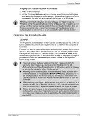
The Grand Tour Memory module slot The memory module slot allows for the installation, replacement and removal of the computer with the display panel open the display, lift the display panel up and position it at a comfortable viewing ...with the display panel open User's Manual 2-7 Display screen Display hinge LCD Sensor switch (Not shown) Display hinge TOSHIBA Assist button Back light On/Off button Fingerprint Sensor Speaker Power button Keyboard Microphone Touch Pad Touch Pad control buttons Figure 2-6 The front of additional memory module. For more detailed information on...
The Grand Tour Memory module slot The memory module slot allows for the installation, replacement and removal of the computer with the display panel open the display, lift the display panel up and position it at a comfortable viewing ...with the display panel open User's Manual 2-7 Display screen Display hinge LCD Sensor switch (Not shown) Display hinge TOSHIBA Assist button Back light On/Off button Fingerprint Sensor Speaker Power button Keyboard Microphone Touch Pad Touch Pad control buttons Figure 2-6 The front of additional memory module. For more detailed information on...
User Manual
Page 75
...'s Manual 4-7 Start up the computer. 2. if the authentication process is not successful within a fixed duration. In addition, you do not want to use the TOSHIBA Password Utility to access the computer when it slowly and at which the finger is swiped. ■ If there are any of the enrolled fingers... Pre-OS Authentication General The fingerprint authentication system can be required to Windows. If the fingerprint authentication process fails you will be used to replace the keyboard based password authentication system that you should try to adjust the speed at a constant speed.
...'s Manual 4-7 Start up the computer. 2. if the authentication process is not successful within a fixed duration. In addition, you do not want to use the TOSHIBA Password Utility to access the computer when it slowly and at which the finger is swiped. ■ If there are any of the enrolled fingers... Pre-OS Authentication General The fingerprint authentication system can be required to Windows. If the fingerprint authentication process fails you will be used to replace the keyboard based password authentication system that you should try to adjust the speed at a constant speed.


