Service Manual
Page 14
... (S-1) (S-5) [4] Jack Bracket [5] BOARD Front Jack Jack Plate Earth Fig. When reassembling, solder wire jumpers as shown in Fig. D1 * [6] DVD Mechanism & DVD Main BOARD Assembly Hook [7] Dust Cover (S-7) [3] Front Bracket (S-3) (S-3) (S-4) (L-1) (S-2) (L-1) (L-1) [2] Panel (L-2) Front CN1231 Fig. Be careful not to place the pin of LD-SW as a unit at factory. D9. 4. D3 (S-6) CN701...
... (S-1) (S-5) [4] Jack Bracket [5] BOARD Front Jack Jack Plate Earth Fig. When reassembling, solder wire jumpers as shown in Fig. D1 * [6] DVD Mechanism & DVD Main BOARD Assembly Hook [7] Dust Cover (S-7) [3] Front Bracket (S-3) (S-3) (S-4) (L-1) (S-2) (L-1) (L-1) [2] Panel (L-2) Front CN1231 Fig. Be careful not to place the pin of LD-SW as a unit at factory. D9. 4. D3 (S-6) CN701...

Service Manual
Page 18
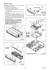
Rotate the gear in the direction of the arrow manually as shown below until the tray descends. 7. Front Bracket Hook View for A A Rotate this gear in the direction of the arrow Dust Cover Panel Front 1-6-6 E9KGADC Remove the DVD Mechanism & DVD Main BOARD Assembly. 5. Pull the tray out manually and remove a disc. Remove the Front Bracket. 4. Unhook two places and detach the Dust Cover. 6. Remove the Cover Top. 2. Remove the Panel Front. 3. 3. How to Eject Manually Note: When rotating the gear, be careful not to damage the gear. 1.
Rotate the gear in the direction of the arrow manually as shown below until the tray descends. 7. Front Bracket Hook View for A A Rotate this gear in the direction of the arrow Dust Cover Panel Front 1-6-6 E9KGADC Remove the DVD Mechanism & DVD Main BOARD Assembly. 5. Pull the tray out manually and remove a disc. Remove the Front Bracket. 4. Unhook two places and detach the Dust Cover. 6. Remove the Cover Top. 2. Remove the Panel Front. 3. 3. How to Eject Manually Note: When rotating the gear, be careful not to damage the gear. 1.


