Service Manual
Page 19
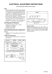
Test point Adj.Point Mode Input TP751(V-OUT) VR1501 TP302(RF-SW) (Switching Point) GND (BOARD MAIN) PLAY (SP) ----- Figure 1 EXT. Syncronize Trigger Point CH1 CH2 1.0H 0.5H 6.5H±1H (416μs±64μs) Switching Pulse V-Sync Reference Notes: Playback the ...: May cause Head Switching noise or vertical jitter in the center position: Press either [TRACKING ] or [TRACKING ] button on the front panel first, then the [ O ] (VCR) button on the front panel. It is at the 6.5H±1H (416μs±64μs) delayed position from the rising edge of the...
Test point Adj.Point Mode Input TP751(V-OUT) VR1501 TP302(RF-SW) (Switching Point) GND (BOARD MAIN) PLAY (SP) ----- Figure 1 EXT. Syncronize Trigger Point CH1 CH2 1.0H 0.5H 6.5H±1H (416μs±64μs) Switching Pulse V-Sync Reference Notes: Playback the ...: May cause Head Switching noise or vertical jitter in the center position: Press either [TRACKING ] or [TRACKING ] button on the front panel first, then the [ O ] (VCR) button on the front panel. It is at the 6.5H±1H (416μs±64μs) delayed position from the rising edge of the...
Service Manual
Page 25
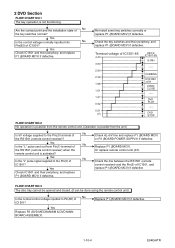
... normal? Terminal voltage of IC1501? Replace P1 (BOARD MCV). Are the contact point and the installation state of No the RS1501 (remote control receiver)? DVD PLAY ----- 2 DVD Section FLOW CHART NO.1 The key operation is not functioning. Or replace remote control unit (X1).
... normal? Terminal voltage of IC1501? Replace P1 (BOARD MCV). Are the contact point and the installation state of No the RS1501 (remote control receiver)? DVD PLAY ----- 2 DVD Section FLOW CHART NO.1 The key operation is not functioning. Or replace remote control unit (X1).
Service Manual
Page 31
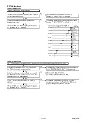
...2.90 2.39 1.98 1.61 1.27 0.92 0.51 (V) KEY-1 IC1501-86 CH DOWN CH UP D/V OUTPUT REC /OTR FF REW PLAY STOP /EJECT POWER FLOW CHART NO.2 No VCR operation is possible from the remote control unit. (Operation is possible from Pin(1) terminal of No the RS1501 (remote control receiver)? Check... the line between the RS1501 (remote control receiver) and the Pin(5) of IC1501? 3 VCR Section FLOW CHART NO.1 The key operation is activated? Re-install some key switches correctly or replace P1 (BOARD MCV) if defective. Yes Check ...
...2.90 2.39 1.98 1.61 1.27 0.92 0.51 (V) KEY-1 IC1501-86 CH DOWN CH UP D/V OUTPUT REC /OTR FF REW PLAY STOP /EJECT POWER FLOW CHART NO.2 No VCR operation is possible from the remote control unit. (Operation is possible from Pin(1) terminal of No the RS1501 (remote control receiver)? Check... the line between the RS1501 (remote control receiver) and the Pin(5) of IC1501? 3 VCR Section FLOW CHART NO.1 The key operation is activated? Re-install some key switches correctly or replace P1 (BOARD MCV) if defective. Yes Check ...
Service Manual
Page 52
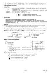
... on the schematics are as shown below: < DVD Section > 1 2 5.0 3 5.0 PLAY mode REC mode (2.5) The same voltage for both PLAY & STOP modes Indicates that the voltage is not consistent here. < VCR Section > 123 PLAY mode 5.0 5.0 REC mode (2.5) DVD mode The same voltage for ordering. CAUTION: Fixed Voltage...Main Fuse (F1001) is used in the parts list section of repaired units, use the part number shown on the drawings for < > both PLAY, REC & DVD Indicates that line number "1" goes to 3 digits) Examples: 2 AREA B1 1. Unit: Volts 5. ABCD 6. This symbol ...
... on the schematics are as shown below: < DVD Section > 1 2 5.0 3 5.0 PLAY mode REC mode (2.5) The same voltage for both PLAY & STOP modes Indicates that the voltage is not consistent here. < VCR Section > 123 PLAY mode 5.0 5.0 REC mode (2.5) DVD mode The same voltage for ordering. CAUTION: Fixed Voltage...Main Fuse (F1001) is used in the parts list section of repaired units, use the part number shown on the drawings for < > both PLAY, REC & DVD Indicates that line number "1" goes to 3 digits) Examples: 2 AREA B1 1. Unit: Volts 5. ABCD 6. This symbol ...


