Service Manual
Page 5
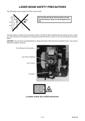
... BEAM SAFETY PRECAUTIONS This DVD player uses a pickup that emits a laser beam. Drive Mechanism Assembly Laser Beam Radiation Laser Pickup Turntable Location: Inside Top of controls and adjustments, or doing procedures other than those specified herein, may result in the figure. CAUTION: Use of DVD mechanism. 1-2-1 RL5NLSP
... BEAM SAFETY PRECAUTIONS This DVD player uses a pickup that emits a laser beam. Drive Mechanism Assembly Laser Beam Radiation Laser Pickup Turntable Location: Inside Top of controls and adjustments, or doing procedures other than those specified herein, may result in the figure. CAUTION: Use of DVD mechanism. 1-2-1 RL5NLSP
Service Manual
Page 19
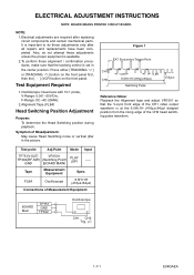
...1H (416μs±64μs) Switching Pulse V-Sync Reference Notes: Playback the Alignment tape and adjust VR1501 so that the tracking control is important to do not attempt these adjustments unless the proper equipment is available. 2.To perform these adjustments only after replacing circuit ... noise or vertical jitter in the center position: Press either [TRACKING ] or [TRACKING ] button on the front panel first, then the [ O ] (VCR) button on the front panel. Test Equipment Required 1.Oscilloscope: Dual-trace with 10:1 probe, V-Range: 0.001~50V/Div., F-Range: DC~AC-20MHz 2....
...1H (416μs±64μs) Switching Pulse V-Sync Reference Notes: Playback the Alignment tape and adjust VR1501 so that the tracking control is important to do not attempt these adjustments unless the proper equipment is available. 2.To perform these adjustments only after replacing circuit ... noise or vertical jitter in the center position: Press either [TRACKING ] or [TRACKING ] button on the front panel first, then the [ O ] (VCR) button on the front panel. Test Equipment Required 1.Oscilloscope: Dual-trace with 10:1 probe, V-Range: 0.001~50V/Div., F-Range: DC~AC-20MHz 2....
Service Manual
Page 20
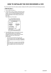
...exits the Version display mode and turns off . 1-8-1 E9KGAINT HOW TO INITIALIZE THE DVD RECORDER & VCR To put the DVD recorder into the Normal mode from the Version display mode, press [RETURN] button on the remote control unit instead of [ENTER] button. * When [ ] button is pressed before [ENTER] button ... power turns off the power automatically. * To move into the Version display mode, press [DVD], [INSTANT SKIP], [1], [2], and [3] buttons on the remote control unit in that the disc tray is one example. To put the program back at the factory-default, initialize the DVD recorder...
...exits the Version display mode and turns off . 1-8-1 E9KGAINT HOW TO INITIALIZE THE DVD RECORDER & VCR To put the DVD recorder into the Normal mode from the Version display mode, press [RETURN] button on the remote control unit instead of [ENTER] button. * When [ ] button is pressed before [ENTER] button ... power turns off the power automatically. * To move into the Version display mode, press [DVD], [INSTANT SKIP], [1], [2], and [3] buttons on the remote control unit in that the disc tray is one example. To put the program back at the factory-default, initialize the DVD recorder...
Service Manual
Page 21
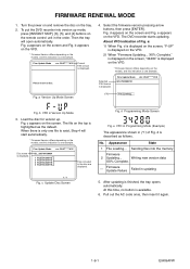
... up mode, press [INSTANT SKIP], [6], [5], and [4] buttons on the models, and this indication is displayed on the VFD. * Firmware Version differs depending on the remote control unit in the order. The file on the tray. 2. d Programming Mode Screen Fig. d is displayed on the VFD. No. Writing new version data XX% Complete...
... up mode, press [INSTANT SKIP], [6], [5], and [4] buttons on the models, and this indication is displayed on the VFD. * Firmware Version differs depending on the remote control unit in the order. The file on the tray. 2. d Programming Mode Screen Fig. d is displayed on the VFD. No. Writing new version data XX% Complete...
Service Manual
Page 25
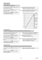
... P1 (BOARD MCV) or P3 (BOARD POWER SUPPLY) if defective. Replace P1 (BOARD MCV) if defective. 1-10-4 E9KGATR Check the line between the RS1501 (remote control receiver) and the Pin(5) of IC1501, and replace P1 (BOARD MCV) if defective FLOW CHART NO.3 The disc tray cannot be opened and closed. (It... can be done using the remote control unit.) No Is the normal control voltage inputted to Pin(85) of IC1501-85 4.30 3.60 2.90 2.39 1.98 1.61 1.27 0.92 0.51 (V) KEY-2 IC1501-85 S-INH ----- Yes...
... P1 (BOARD MCV) or P3 (BOARD POWER SUPPLY) if defective. Replace P1 (BOARD MCV) if defective. 1-10-4 E9KGATR Check the line between the RS1501 (remote control receiver) and the Pin(5) of IC1501, and replace P1 (BOARD MCV) if defective FLOW CHART NO.3 The disc tray cannot be opened and closed. (It... can be done using the remote control unit.) No Is the normal control voltage inputted to Pin(85) of IC1501-85 4.30 3.60 2.90 2.39 1.98 1.61 1.27 0.92 0.51 (V) KEY-2 IC1501-85 S-INH ----- Yes...
Service Manual
Page 31
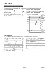
3 VCR Section FLOW CHART NO.1 The key operation is activated? Check the key switches and their periphery, and replace P1 (BOARD MCV) if defective. Or replace remote control unit (X1). Yes No Is the "L" pulse sent out from the unit.) Is 5V voltage supplied to the Pin...POWER FLOW CHART NO.2 No VCR operation is possible from the remote control unit. (Operation is possible from Pin(1) terminal of No the RS1501 (remote control receiver)? Check the line between the RS1501 (remote control receiver) and the Pin(5) of IC1501? Yes Is the control voltage normally inputted into No...
3 VCR Section FLOW CHART NO.1 The key operation is activated? Check the key switches and their periphery, and replace P1 (BOARD MCV) if defective. Or replace remote control unit (X1). Yes No Is the "L" pulse sent out from the unit.) Is 5V voltage supplied to the Pin...POWER FLOW CHART NO.2 No VCR operation is possible from the remote control unit. (Operation is possible from Pin(1) terminal of No the RS1501 (remote control receiver)? Check the line between the RS1501 (remote control receiver) and the Pin(5) of IC1501? Yes Is the control voltage normally inputted into No...
Service Manual
Page 40
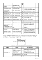
...Recording Compatible setting was turned off was recorded. 7 If an error occurs during recording. You cannot record more than 49 titles on the disc as Control Information is Full. (in REC start) 4 full. maximum is 49.) 43 The 49 titles has been reached. (+VR Format) 9 You ...disc is inserted. Repeat the same operation. 38 Sector Address is displayed on the recording menu after timer recording. (Once the screen of control information. 10 You cannot record on one disc. Videotape ran out during the timer recording, one disc.(The maximum is 254.) Delete ...
...Recording Compatible setting was turned off was recorded. 7 If an error occurs during recording. You cannot record more than 49 titles on the disc as Control Information is Full. (in REC start) 4 full. maximum is 49.) 43 The 49 titles has been reached. (+VR Format) 9 You ...disc is inserted. Repeat the same operation. 38 Sector Address is displayed on the recording menu after timer recording. (Once the screen of control information. 10 You cannot record on one disc. Videotape ran out during the timer recording, one disc.(The maximum is 254.) Delete ...
Service Manual
Page 41
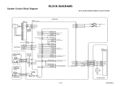
...SDA 17 Hi-Fi-H-SW 30 Hi-Fi/NOR-IN 78 12 P4 13 P5 14 P6 16 P7 VCR-AUDIO-MUTE 31 D-REC 29 Q1501 TIMER+5V RESET 25 RESET TO POWER SUPPLY BLOCK DIAGRAM REG-CONT2 REG...21 C-SYNC-IN 50 D-V SYNC 24 V-ENV 83 C-ROTA 98 RF-SW 23 H-A-SW 99 BOARD POWER SWITCH KEY SWITCH (VCR) H-A-COMP 100 VIDEO-SW1 59 VIDEO-SW2 58 SW1620 VIDEO-SW3 57 POWER CN2212 CN2211 D1569 POWER 4 POWER-SW 4 1...BLOCK DIAGRAM TO AUDIO INPUT/OUTPUT SELECT BLOCK DIAGRAM 1-12-1 VCR-LED 94 VCR-LED 95 DVD-LED 96 DVD-LED 97 D1563 D1562 VCR DVD AL+5V IC101 MAIN MICRO CONTROLLER SYS-RESET 44 S-DATA-OUT 16 S-DATA-IN 15 S-...
...SDA 17 Hi-Fi-H-SW 30 Hi-Fi/NOR-IN 78 12 P4 13 P5 14 P6 16 P7 VCR-AUDIO-MUTE 31 D-REC 29 Q1501 TIMER+5V RESET 25 RESET TO POWER SUPPLY BLOCK DIAGRAM REG-CONT2 REG...21 C-SYNC-IN 50 D-V SYNC 24 V-ENV 83 C-ROTA 98 RF-SW 23 H-A-SW 99 BOARD POWER SWITCH KEY SWITCH (VCR) H-A-COMP 100 VIDEO-SW1 59 VIDEO-SW2 58 SW1620 VIDEO-SW3 57 POWER CN2212 CN2211 D1569 POWER 4 POWER-SW 4 1...BLOCK DIAGRAM TO AUDIO INPUT/OUTPUT SELECT BLOCK DIAGRAM 1-12-1 VCR-LED 94 VCR-LED 95 DVD-LED 96 DVD-LED 97 D1563 D1562 VCR DVD AL+5V IC101 MAIN MICRO CONTROLLER SYS-RESET 44 S-DATA-OUT 16 S-DATA-IN 15 S-...
Service Manual
Page 42
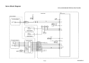
...-S BOARD SENSOR Q1503 END-S BOARD SENSOR CYLINDER ASSEMBLY PG SENSOR M DRUM MOTOR LOADING M MOTOR CAPSTAN MOTOR CAPSTAN MOTOR M MOTOR DRIVE CIRCUIT BOARD MAIN IC1501 (SERVO CONTROL) TP506 TP505 TP507 ST-S T-REEL END-S Q1506 T-REEL TP513 CTL SW1512 AL+5V(1) MODE-SW 76 CTL 74 CTL(+) 75 CTL(-) 87 LD-SW 88...
...-S BOARD SENSOR Q1503 END-S BOARD SENSOR CYLINDER ASSEMBLY PG SENSOR M DRUM MOTOR LOADING M MOTOR CAPSTAN MOTOR CAPSTAN MOTOR M MOTOR DRIVE CIRCUIT BOARD MAIN IC1501 (SERVO CONTROL) TP506 TP505 TP507 ST-S T-REEL END-S Q1506 T-REEL TP513 CTL SW1512 AL+5V(1) MODE-SW 76 CTL 74 CTL(+) 75 CTL(-) 87 LD-SW 88...

Service Manual
Page 45
... BUFFER + DIAGRAM VIDEO1 8 VIDEO2 10 PB/EE 12 MUTE (VCR DVD DUBBING) VCR-VIDEO(DUB) TO VIDEO BLOCK DIAGRAM YC G G JK2401 S-VIDEO IN1 REAR JK2804 VIDEO - IN1 VIDEO-IN1 TO VIDEO OUTPUT SELECT BLOCK DIAGRAM DVD MAIN BOARD Q2304 BUFFER 21 BUFFER LPF CONTROL LOGIC C1 2 MUTE 22 23 24 VIDEO-SW1 VIDEO...
... BUFFER + DIAGRAM VIDEO1 8 VIDEO2 10 PB/EE 12 MUTE (VCR DVD DUBBING) VCR-VIDEO(DUB) TO VIDEO BLOCK DIAGRAM YC G G JK2401 S-VIDEO IN1 REAR JK2804 VIDEO - IN1 VIDEO-IN1 TO VIDEO OUTPUT SELECT BLOCK DIAGRAM DVD MAIN BOARD Q2304 BUFFER 21 BUFFER LPF CONTROL LOGIC C1 2 MUTE 22 23 24 VIDEO-SW1 VIDEO...

Service Manual
Page 47
...+5V(2) SWITCHING Q1425 D-REC OFF P-ON+5V(2) REC 9 AMP SERIAL I/F 58 55 53 54 YCA-SDA YCA-SCL YCA-CS AUDIO-MUTE D-REC TO SYSTEM CONTROL BLOCK DIAGRAM 1-12-7 E9KGABLA
...+5V(2) SWITCHING Q1425 D-REC OFF P-ON+5V(2) REC 9 AMP SERIAL I/F 58 55 53 54 YCA-SDA YCA-SCL YCA-CS AUDIO-MUTE D-REC TO SYSTEM CONTROL BLOCK DIAGRAM 1-12-7 E9KGABLA

Service Manual
Page 48
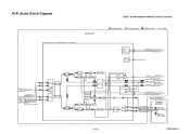
...OUT-L PB AUDIO SIGNAL JK2751 (REAR) AUDIO(L) -OUT2 AUDIO(R) -OUT2 9 10 11 OUTPUT-SELECT TO SYSTEM CONTROL BLOCK DIAGRAM Q2804 DRIVE Q2806 MUTE-ON JK2805 (REAR) AUDIO(L) -OUT1 Q2805 MUTE-ON AUDIO(R) -OUT1 VCR PB (VCR DVD DUBBING) IC2803 (OP AMP) 1 OP AMP 2 7 OP AMP 6 IC2801 (INPUT SELECT) (L-CH) ...IN LINE(L)-OUT LINE(R)-OUT TO Hi-Fi AUDIO BLOCK DIAGRAM Q2101 BUFFER Q2102 BUFFER JK2804 (REAR) AUDIO(L) -IN1 AUDIO(R) -IN1 TO SYSTEM CONTROL BLOCK DIAGRAM AUDIO-SW2 AUDIO-SW1 OUTPUT-SELECT2 SW CTL 9 10 BOARD MAIN BOARD FRONT JACK JK1232 CN2609 CN1231 3 AUDIO(L)-IN2 3 5 ...
...OUT-L PB AUDIO SIGNAL JK2751 (REAR) AUDIO(L) -OUT2 AUDIO(R) -OUT2 9 10 11 OUTPUT-SELECT TO SYSTEM CONTROL BLOCK DIAGRAM Q2804 DRIVE Q2806 MUTE-ON JK2805 (REAR) AUDIO(L) -OUT1 Q2805 MUTE-ON AUDIO(R) -OUT1 VCR PB (VCR DVD DUBBING) IC2803 (OP AMP) 1 OP AMP 2 7 OP AMP 6 IC2801 (INPUT SELECT) (L-CH) ...IN LINE(L)-OUT LINE(R)-OUT TO Hi-Fi AUDIO BLOCK DIAGRAM Q2101 BUFFER Q2102 BUFFER JK2804 (REAR) AUDIO(L) -IN1 AUDIO(R) -IN1 TO SYSTEM CONTROL BLOCK DIAGRAM AUDIO-SW2 AUDIO-SW1 OUTPUT-SELECT2 SW CTL 9 10 BOARD MAIN BOARD FRONT JACK JK1232 CN2609 CN1231 3 AUDIO(L)-IN2 3 5 ...
Service Manual
Page 49
...69 71 TO AUDIO BLOCK N-A-OUT 6 DIAGRAM LINE(R)-IN TO AUDIO LINE(L)-IN 7 INPUT /OUTPUT SELECT BLOCK DVD-AUDIO(L) DVD-AUDIO(R) 9 DIAGRAM DVD PB (DVD VCR DUBBING) R-CH INSEL 48 47 NOR SW L-CH 13 14 INSEL R-CH PNR P SW NOISE COMP R-CH BPF R LIM DEV VCO LPF OUTPUT SELECT DO...DET HOLD PULSE NOISE DET MATRIX COMP L-CH PNR LIM DEV VCO LPF R SW P NOISE COMP L-CH BPF R LIM 34 33 L TO SYSTEM 23 NORMAL-L CONTROL BLOCK DIAGRAM N-A-IN TO AUDIO 4 BLOCK DIAGRAM 80 LINE(L)-OUT TO AUDIO INPUT/OUTPUT LINE(R)-OUT SELECT BLOCK 78 DIAGRAM 77 1 Hi-Fi-H-SW TO...
...69 71 TO AUDIO BLOCK N-A-OUT 6 DIAGRAM LINE(R)-IN TO AUDIO LINE(L)-IN 7 INPUT /OUTPUT SELECT BLOCK DVD-AUDIO(L) DVD-AUDIO(R) 9 DIAGRAM DVD PB (DVD VCR DUBBING) R-CH INSEL 48 47 NOR SW L-CH 13 14 INSEL R-CH PNR P SW NOISE COMP R-CH BPF R LIM DEV VCO LPF OUTPUT SELECT DO...DET HOLD PULSE NOISE DET MATRIX COMP L-CH PNR LIM DEV VCO LPF R SW P NOISE COMP L-CH BPF R LIM 34 33 L TO SYSTEM 23 NORMAL-L CONTROL BLOCK DIAGRAM N-A-IN TO AUDIO 4 BLOCK DIAGRAM 80 LINE(L)-OUT TO AUDIO INPUT/OUTPUT LINE(R)-OUT SELECT BLOCK 78 DIAGRAM 77 1 Hi-Fi-H-SW TO...
Service Manual
Page 50
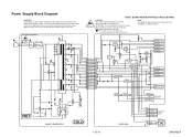
...+2.8V P-ON+1.8V -FL F1 F2 IC1010 ERROR Q1031 VOLTAGE DET Q2206 Q2205 SWITCHING SWITCHING P-DOWN-H PWR-SW P-ON-L REG-CONT1 REG-CONT2 TO SYSTEM CONTROL BLOCK DIAGRAM Q1008 HOT 4 1 3 2 BOARD POWER SUPPLY COLD BOARD MAIN CN2204 20-22 P-ON+5V 10-12 EV+2.8V 15-17 P-ON+3.3V 6,7 P-ON+1.8V...
...+2.8V P-ON+1.8V -FL F1 F2 IC1010 ERROR Q1031 VOLTAGE DET Q2206 Q2205 SWITCHING SWITCHING P-DOWN-H PWR-SW P-ON-L REG-CONT1 REG-CONT2 TO SYSTEM CONTROL BLOCK DIAGRAM Q1008 HOT 4 1 3 2 BOARD POWER SUPPLY COLD BOARD MAIN CN2204 20-22 P-ON+5V 10-12 EV+2.8V 15-17 P-ON+3.3V 6,7 P-ON+1.8V...
Service Manual
Page 75
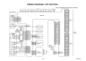
... ASSEMBLY AUDIO ERASE HEAD CN1504 1 AE-H 2 AE-H/FE-H BOARD MAIN GND 23 P-ON+5V 22 P-ON+5V 21 P-ON+5V 20 GND 19 AUDIO HEAD CONTROL HEAD 3 A-COM 4 AUDIO-PB/REC 5 CTL(+) 6 CTL(-) FE HEAD FULL ERASE HEAD LOADING MOTOR M CAPSTAN MOTOR M CYLINDER ASSEMBLY PG SENSOR M DRUM MOTOR VIDEO (R)1 HEAD VIDEO... CN101 TO DVD MAIN BOARD CN701 TO WIRING DIAGRAM VIDEO-Y(I)-OUT 1 1-15-1 E9KGAWI REAR S-VIDEO S-VIDEO VIDEO OUT IN OUT AUDIO(L) -OUT2 VIDEO- WIRING DIAGRAM< VCR SECTION > NOTE: BOARD MEANS PRINTED CIRCUIT BOARD.
... ASSEMBLY AUDIO ERASE HEAD CN1504 1 AE-H 2 AE-H/FE-H BOARD MAIN GND 23 P-ON+5V 22 P-ON+5V 21 P-ON+5V 20 GND 19 AUDIO HEAD CONTROL HEAD 3 A-COM 4 AUDIO-PB/REC 5 CTL(+) 6 CTL(-) FE HEAD FULL ERASE HEAD LOADING MOTOR M CAPSTAN MOTOR M CYLINDER ASSEMBLY PG SENSOR M DRUM MOTOR VIDEO (R)1 HEAD VIDEO... CN101 TO DVD MAIN BOARD CN701 TO WIRING DIAGRAM VIDEO-Y(I)-OUT 1 1-15-1 E9KGAWI REAR S-VIDEO S-VIDEO VIDEO OUT IN OUT AUDIO(L) -OUT2 VIDEO- WIRING DIAGRAM< VCR SECTION > NOTE: BOARD MEANS PRINTED CIRCUIT BOARD.
Service Manual
Page 77
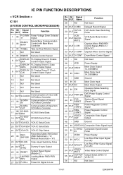
...Used 29 OUT D-REC Delayed Record Signal 30 OUT Hi-Fi-HSW VCR31 OUT AUDIO- NU Not Used 1-16-1 E9KGAPIN IC PIN FUNCTION DESCRIPTIONS < VCR Section > IC1501 (SYSTEM CONTROL MICROPROCESSOR) Pin IN/ Signal No. NU Not Used 13 - OUT Name Function 28 - NU Not Used 12 - VDD Power Supply 37 OUT...C-SYNCIN Composite Synchronized Pulse 51 - NU Not Used 36 - NU Not Used 10 - NU Not Used 14 OUT S-CLOCK Communication of Data from VCR Micro Controller IIC BUS Serial Data IIC BUS Serial Clock 19 OUT YCA-SCL YCA IC Serial Clock 20 OUT YCA-SDA YCA IC Serial Data 21...
...Used 29 OUT D-REC Delayed Record Signal 30 OUT Hi-Fi-HSW VCR31 OUT AUDIO- NU Not Used 1-16-1 E9KGAPIN IC PIN FUNCTION DESCRIPTIONS < VCR Section > IC1501 (SYSTEM CONTROL MICROPROCESSOR) Pin IN/ Signal No. NU Not Used 13 - OUT Name Function 28 - NU Not Used 12 - VDD Power Supply 37 OUT...C-SYNCIN Composite Synchronized Pulse 51 - NU Not Used 36 - NU Not Used 10 - NU Not Used 14 OUT S-CLOCK Communication of Data from VCR Micro Controller IIC BUS Serial Data IIC BUS Serial Clock 19 OUT YCA-SCL YCA IC Serial Clock 20 OUT YCA-SDA YCA IC Serial Data 21...
Service Manual
Page 78
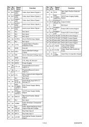
... Used 63 - NU 64 - GND Ground 69 OUT VRO Servo Standard Voltage Output 70 IN VRI Servo Standard Voltage Input 71 - Output Control Signal for Test Point 77 - OUT Name 57 OUT VIDEOSW3 Function Video Input Select Signal 3 58 OUT VIDEOSW2 59 OUT VIDEOSW1 60 OUT ...- NU Not Used 92 OUT POWERLED Power LED Control Signal 93 OUT POWERLED Power LED Control Signal 94 OUT VCR-LED VCR LED Control Signal 95 OUT VCR-LED VCRLED Control Signal 96 OUT DVD-LED DVD LED Control Signal 97 OUT DVD-LED DVD LED Control Signal 98 OUT C-ROTA Color Phase Rotary Changeover Signal...
... Used 63 - NU 64 - GND Ground 69 OUT VRO Servo Standard Voltage Output 70 IN VRI Servo Standard Voltage Input 71 - Output Control Signal for Test Point 77 - OUT Name 57 OUT VIDEOSW3 Function Video Input Select Signal 3 58 OUT VIDEOSW2 59 OUT VIDEOSW1 60 OUT ...- NU Not Used 92 OUT POWERLED Power LED Control Signal 93 OUT POWERLED Power LED Control Signal 94 OUT VCR-LED VCR LED Control Signal 95 OUT VCR-LED VCRLED Control Signal 96 OUT DVD-LED DVD LED Control Signal 97 OUT DVD-LED DVD LED Control Signal 98 OUT C-ROTA Color Phase Rotary Changeover Signal...

Service Manual
Page 85
... P000501410 N2465FL DECK ASSEMBLY CZD014/ VM2465 FM1001 P000490010 MMEZR12XNR01 MOTOR DC FAN 2D65BK100100 W2 P000501450 WPZ0221WJ001 WIRE TIE 220MM BLACK ACCESSORIES X1 P000501430 NB340UD REMOTE CONTROL UNIT NB340UD X5 P000457360 WPZ0152TM014 AV CORD WPZ0152TM014 ! MECHANICAL PARTS LIST PRODUCT SAFETY NOTE: Products marked with a ! X20 P000501330 1VMN24593 OWNERS MANUAL E9KGAUD X22A P000501340...
... P000501410 N2465FL DECK ASSEMBLY CZD014/ VM2465 FM1001 P000490010 MMEZR12XNR01 MOTOR DC FAN 2D65BK100100 W2 P000501450 WPZ0221WJ001 WIRE TIE 220MM BLACK ACCESSORIES X1 P000501430 NB340UD REMOTE CONTROL UNIT NB340UD X5 P000457360 WPZ0152TM014 AV CORD WPZ0152TM014 ! MECHANICAL PARTS LIST PRODUCT SAFETY NOTE: Products marked with a ! X20 P000501330 1VMN24593 OWNERS MANUAL E9KGAUD X22A P000501340...


