Service Manual
Page 3
... for Servicing 1-4-1 Preparation for Servicing 1-5-1 Cabinet Disassembly Instructions 1-6-1 Electrical Adjustment Instructions 1-7-1 How to Initialize the DVD Recorder & VCR 1-8-1 Firmware Renewal Mode 1-9-1 Troubleshooting 1-10-1 Function Indicator Symbols 1-11-1 Block Diagrams 1-12-1 Schematic Diagrams / BOARD's... and Test Points 1-13-1 Waveforms 1-14-1 Wiring Diagram < VCR Section 1-15-1 Wiring Diagram < DVD Section 1-15-2 IC Pin Function Descriptions 1-16-1 Lead Identifications 1-17-1 Exploded Views 1-18-1 Mechanical Parts...
... for Servicing 1-4-1 Preparation for Servicing 1-5-1 Cabinet Disassembly Instructions 1-6-1 Electrical Adjustment Instructions 1-7-1 How to Initialize the DVD Recorder & VCR 1-8-1 Firmware Renewal Mode 1-9-1 Troubleshooting 1-10-1 Function Indicator Symbols 1-11-1 Block Diagrams 1-12-1 Schematic Diagrams / BOARD's... and Test Points 1-13-1 Waveforms 1-14-1 Wiring Diagram < VCR Section 1-15-1 Wiring Diagram < DVD Section 1-15-2 IC Pin Function Descriptions 1-16-1 Lead Identifications 1-17-1 Exploded Views 1-18-1 Mechanical Parts...
Service Manual
Page 4
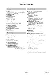
...Recording Recording format VR (video recording) format Video format +VR format Recording discs DVD-Rewritable/-Recordable, DVD+Rewritable/+Recordable Video recording format Sampling frequency: 13.5 MHz Compression format: MPEG Audio recording format Sampling frequency: 48 kHz Compression format: Dolby Digital/LPCM (XP Recording... C (color) - Output level: 1 Vp-p (75Ω) C (color) - SPECIFICATIONS General System DVD-RW/-R, DVD+RW/+R, DVD-video, CD-DA, CD-RW/-R, VHS cassette tape VCR Video Heads Four heads Power requirements AC120 V, 60 Hz Power consumption 30W(standby: 3.3 W) Weight 9.5 lbs ...
...Recording Recording format VR (video recording) format Video format +VR format Recording discs DVD-Rewritable/-Recordable, DVD+Rewritable/+Recordable Video recording format Sampling frequency: 13.5 MHz Compression format: MPEG Audio recording format Sampling frequency: 48 kHz Compression format: Dolby Digital/LPCM (XP Recording... C (color) - Output level: 1 Vp-p (75Ω) C (color) - SPECIFICATIONS General System DVD-RW/-R, DVD+RW/+R, DVD-video, CD-DA, CD-RW/-R, VHS cassette tape VCR Video Heads Four heads Power requirements AC120 V, 60 Hz Power consumption 30W(standby: 3.3 W) Weight 9.5 lbs ...
Service Manual
Page 20
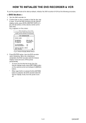
... DISC ADJUSTMENT : OK DEFAULT SETTING : ENTER EXIT : RETURN Fig. When the initializing is completed, the DVD recorder exits the Version display mode and turns off . 1-8-1 E9KGAINT a Version Display Mode Screen 3. HOW TO INITIALIZE THE DVD RECORDER & VCR To put the DVD recorder into the Normal mode from the Version display mode, press [RETURN] button on the remote...
... DISC ADJUSTMENT : OK DEFAULT SETTING : ENTER EXIT : RETURN Fig. When the initializing is completed, the DVD recorder exits the Version display mode and turns off . 1-8-1 E9KGAINT a Version Display Mode Screen 3. HOW TO INITIALIZE THE DVD RECORDER & VCR To put the DVD recorder into the Normal mode from the Version display mode, press [RETURN] button on the remote...
Service Manual
Page 77
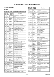
... OUT D-REC Delayed Record Signal 30 OUT Hi-Fi-HSW VCR31 OUT AUDIO- VDD2 Power Supply 52 IN AFCC Low Pass Filter Input Signal For AFC 53 OUT AFCLPF Low Pass Filter Output Signal For AFC 54 OUT VIDEOMUTE Video Mute Control Signal 55 OUT OUTPUTSELECT Output Select (DVD="L"/ VCR="H") 56 - NU Not... of Data from VCR Micro Controller IIC BUS Serial Data IIC BUS Serial Clock 19 OUT YCA-SCL YCA IC Serial Clock 20 OUT YCA-SDA YCA IC Serial Data 21 OUT YCA-CS YCA IC Chip Select 22 IN RECSAF-SW Recording Safety SW Detect (With Record tab = "L"/ Without Record tab = "H") 23 ...
... OUT D-REC Delayed Record Signal 30 OUT Hi-Fi-HSW VCR31 OUT AUDIO- VDD2 Power Supply 52 IN AFCC Low Pass Filter Input Signal For AFC 53 OUT AFCLPF Low Pass Filter Output Signal For AFC 54 OUT VIDEOMUTE Video Mute Control Signal 55 OUT OUTPUTSELECT Output Select (DVD="L"/ VCR="H") 56 - NU Not... of Data from VCR Micro Controller IIC BUS Serial Data IIC BUS Serial Clock 19 OUT YCA-SCL YCA IC Serial Clock 20 OUT YCA-SDA YCA IC Serial Data 21 OUT YCA-CS YCA IC Chip Select 22 IN RECSAF-SW Recording Safety SW Detect (With Record tab = "L"/ Without Record tab = "H") 23 ...
Service Manual
Page 78
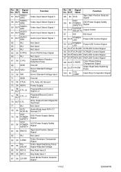
... Playback/Record Control Signal (-) 76 OUT CTL Amp. Output Control Signal for Test Point 77 - NU Not Used 92 OUT POWERLED Power LED Control Signal 93 OUT POWERLED Power LED Control Signal 94 OUT VCR-LED VCR LED Control Signal 95 OUT VCR-LED VCRLED Control Signal 96 OUT DVD-LED DVD LED... Control Signal 97 OUT DVD-LED DVD LED Control Signal 98 OUT C-ROTA Color Phase Rotary Changeover Signal 99 OUT ...
... Playback/Record Control Signal (-) 76 OUT CTL Amp. Output Control Signal for Test Point 77 - NU Not Used 92 OUT POWERLED Power LED Control Signal 93 OUT POWERLED Power LED Control Signal 94 OUT VCR-LED VCR LED Control Signal 95 OUT VCR-LED VCRLED Control Signal 96 OUT DVD-LED DVD LED... Control Signal 97 OUT DVD-LED DVD LED Control Signal 98 OUT C-ROTA Color Phase Rotary Changeover Signal 99 OUT ...


