Service Manual
Page 1
For (*1) and (*2), see the next page. TOSHIBA CORPORATION 2008 Published in this manual and lead-free solder (*2). This Service Manual describes replacement parts for the green product. When repairing this green product, use the part(s) described in Japan, Jan. 2008 GREEN SERVICE MANUAL FILE NO. 810-200803GR DVD Video Recorder /Video Cassette Recorder D-VR610KU The above model is classified as a green product (*1), as indicated by the underlined serial number.
For (*1) and (*2), see the next page. TOSHIBA CORPORATION 2008 Published in this manual and lead-free solder (*2). This Service Manual describes replacement parts for the green product. When repairing this green product, use the part(s) described in Japan, Jan. 2008 GREEN SERVICE MANUAL FILE NO. 810-200803GR DVD Video Recorder /Video Cassette Recorder D-VR610KU The above model is classified as a green product (*1), as indicated by the underlined serial number.
Service Manual
Page 3
...Notes for Servicing 1-4-1 Preparation for Servicing 1-5-1 Cabinet Disassembly Instructions 1-6-1 Electrical Adjustment Instructions 1-7-1 How to Initialize the DVD Recorder & VCR 1-8-1 Firmware Renewal Mode 1-9-1 Troubleshooting 1-10-1 Function Indicator Symbols 1-11-1 Block Diagrams 1-12-1 Schematic Diagrams / BOARD's... and Test Points 1-13-1 Waveforms 1-14-1 Wiring Diagram < VCR Section 1-15-1 Wiring Diagram < DVD Section 1-15-2 IC Pin Function Descriptions 1-16-1 Lead Identifications 1-17-1 Exploded Views 1-18-1 Mechanical Parts...
...Notes for Servicing 1-4-1 Preparation for Servicing 1-5-1 Cabinet Disassembly Instructions 1-6-1 Electrical Adjustment Instructions 1-7-1 How to Initialize the DVD Recorder & VCR 1-8-1 Firmware Renewal Mode 1-9-1 Troubleshooting 1-10-1 Function Indicator Symbols 1-11-1 Block Diagrams 1-12-1 Schematic Diagrams / BOARD's... and Test Points 1-13-1 Waveforms 1-14-1 Wiring Diagram < VCR Section 1-15-1 Wiring Diagram < DVD Section 1-15-2 IC Pin Function Descriptions 1-16-1 Lead Identifications 1-17-1 Exploded Views 1-18-1 Mechanical Parts...
Service Manual
Page 4
Output level: 1 Vp-p (75Ω) C (color) - SPECIFICATIONS General System DVD-RW/-R, DVD+RW/+R, DVD-video, CD-DA, CD-RW/-R, VHS cassette tape VCR Video Heads Four heads Power requirements AC120 V, 60 Hz Power consumption 30W(standby: 3.3 W) Weight 9.5 lbs ( 4.3 kg ) Dimensions (width x height x...) TV format NTSC TV standard Recording Recording format VR (video recording) format Video format +VR format Recording discs DVD-Rewritable/-Recordable, DVD+Rewritable/+Recordable Video recording format Sampling frequency: 13.5 MHz Compression format: MPEG Audio recording format Sampling frequency: 48 ...
Output level: 1 Vp-p (75Ω) C (color) - SPECIFICATIONS General System DVD-RW/-R, DVD+RW/+R, DVD-video, CD-DA, CD-RW/-R, VHS cassette tape VCR Video Heads Four heads Power requirements AC120 V, 60 Hz Power consumption 30W(standby: 3.3 W) Weight 9.5 lbs ( 4.3 kg ) Dimensions (width x height x...) TV format NTSC TV standard Recording Recording format VR (video recording) format Video format +VR format Recording discs DVD-Rewritable/-Recordable, DVD+Rewritable/+Recordable Video recording format Sampling frequency: 13.5 MHz Compression format: MPEG Audio recording format Sampling frequency: 48 ...
Service Manual
Page 5
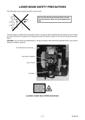
... the laser beam coming from the location shown in hazardous radiation exposure. LASER BEAM SAFETY PRECAUTIONS This DVD player uses a pickup that emits a laser beam. The laser beam is turned on. CAUTION: Use of DVD mechanism. 1-2-1 RL5NLSP Do not look directly at least 30 cm away from the pickup lens when the...
... the laser beam coming from the location shown in hazardous radiation exposure. LASER BEAM SAFETY PRECAUTIONS This DVD player uses a pickup that emits a laser beam. The laser beam is turned on. CAUTION: Use of DVD mechanism. 1-2-1 RL5NLSP Do not look directly at least 30 cm away from the pickup lens when the...
Service Manual
Page 13
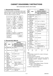
... Unit [13] BOARD Holder [15] Deck Assembly [16] BOARD Power Switch [17] BOARD DVD open / close Switch [14] VCR Chassis Unit [18] BOARD Main [19] Deck Pedestal 2. No. CABINET DISASSEMBLY INSTRUCTIONS NOTE: BOARD MEANS PRINTED CIRCUIT BOARD. 1. DVD Mechanism 4(S-6), (S-6a), (S-7), [6] & DVD Main D4 *CN101, *CN701, *CN901, Mecha Plate 4 BOARD Earth R Assembly [7] Dust Cover D4...
... Unit [13] BOARD Holder [15] Deck Assembly [16] BOARD Power Switch [17] BOARD DVD open / close Switch [14] VCR Chassis Unit [18] BOARD Main [19] Deck Pedestal 2. No. CABINET DISASSEMBLY INSTRUCTIONS NOTE: BOARD MEANS PRINTED CIRCUIT BOARD. 1. DVD Mechanism 4(S-6), (S-6a), (S-7), [6] & DVD Main D4 *CN101, *CN701, *CN901, Mecha Plate 4 BOARD Earth R Assembly [7] Dust Cover D4...
Service Manual
Page 14
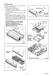
Be careful not to place the pin of LD-SW as shown in Fig. The DVD Mechanism & DVD Main BOARD Assembly is adjusted as a unit. (S-1) [1] Cover Top (S-1) (S-5) [4] Jack Bracket [5] BOARD Front Jack Jack Plate Earth Fig. D1 * [6] DVD Mechanism & DVD Main BOARD Assembly Hook [7] Dust Cover (S-7) [3] Front Bracket (S-3) (S-3) (S-4) (L-1) (S-2) (L-1) (L-1) [2] ...Before installing the Deck Assembly, be sure to break them. 1-1. Reference Notes CAUTION 1: Locking Tabs (L-1) and (L-2) are fragile. Replace the DVD Mechanism & DVD Main BOARD Assembly as a unit at factory. D9.
Be careful not to place the pin of LD-SW as shown in Fig. The DVD Mechanism & DVD Main BOARD Assembly is adjusted as a unit. (S-1) [1] Cover Top (S-1) (S-5) [4] Jack Bracket [5] BOARD Front Jack Jack Plate Earth Fig. D1 * [6] DVD Mechanism & DVD Main BOARD Assembly Hook [7] Dust Cover (S-7) [3] Front Bracket (S-3) (S-3) (S-4) (L-1) (S-2) (L-1) (L-1) [2] ...Before installing the Deck Assembly, be sure to break them. 1-1. Reference Notes CAUTION 1: Locking Tabs (L-1) and (L-2) are fragile. Replace the DVD Mechanism & DVD Main BOARD Assembly as a unit at factory. D9.

Service Manual
Page 16
... Head Assembly Pin SW1512 LD-SW [16] BOARD Power Switch (S-19) Lead with blue stripe Desolder [18] BOARD Main [18] BOARD Main (S-20) [17] BOARD DVD open/close Switch Desolder Lead with blue stripe [15] Deck Assembly Shaft Cam Gear Hole Hole LD-SW Pin [18] BOARD Main From Capstan Motor...
... Head Assembly Pin SW1512 LD-SW [16] BOARD Power Switch (S-19) Lead with blue stripe Desolder [18] BOARD Main [18] BOARD Main (S-20) [17] BOARD DVD open/close Switch Desolder Lead with blue stripe [15] Deck Assembly Shaft Cam Gear Hole Hole LD-SW Pin [18] BOARD Main From Capstan Motor...

Service Manual
Page 18
Unhook two places and detach the Dust Cover. 6. 3. Remove the Cover Top. 2. Remove the DVD Mechanism & DVD Main BOARD Assembly. 5. Pull the tray out manually and remove a disc. Remove the Panel Front. 3. Rotate the gear in the direction of the arrow manually as shown below until the tray descends. 7. How to Eject Manually Note: When rotating the gear, be careful not to damage the gear. 1. Remove the Front Bracket. 4. Front Bracket Hook View for A A Rotate this gear in the direction of the arrow Dust Cover Panel Front 1-6-6 E9KGADC
Unhook two places and detach the Dust Cover. 6. 3. Remove the Cover Top. 2. Remove the DVD Mechanism & DVD Main BOARD Assembly. 5. Pull the tray out manually and remove a disc. Remove the Panel Front. 3. Rotate the gear in the direction of the arrow manually as shown below until the tray descends. 7. How to Eject Manually Note: When rotating the gear, be careful not to damage the gear. 1. Remove the Front Bracket. 4. Front Bracket Hook View for A A Rotate this gear in the direction of the arrow Dust Cover Panel Front 1-6-6 E9KGADC
Service Manual
Page 20
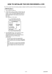
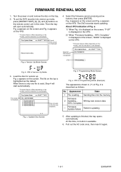
...Version display mode and turns off . 1-8-1 E9KGAINT a Version Display Mode Screen 3. Fig. HOW TO INITIALIZE THE DVD RECORDER & VCR To put the DVD recorder into the Normal mode from the Version display mode, press [RETURN] button on the remote control unit in ...that the disc tray is one example. To put the program back at the factory-default, initialize the DVD recorder & VCR as the following procedure. < DVD Section > 1. F/W VERSION DISP MODEL NAME : FE VERSION : BE VERSION : TT VERSION : ******* R50_015_000 WL5T34280H1E T50014WLU LD ADJUSTMENT...
...Version display mode and turns off . 1-8-1 E9KGAINT a Version Display Mode Screen 3. Fig. HOW TO INITIALIZE THE DVD RECORDER & VCR To put the DVD recorder into the Normal mode from the Version display mode, press [RETURN] button on the remote control unit in ...that the disc tray is one example. To put the program back at the factory-default, initialize the DVD recorder & VCR as the following procedure. < DVD Section > 1. F/W VERSION DISP MODEL NAME : FE VERSION : BE VERSION : TT VERSION : ******* R50_015_000 WL5T34280H1E T50014WLU LD ADJUSTMENT...
Service Manual
Page 21
a Version Up Mode Screen 4. Fig. The DVD recorder starts updating. e: 1) When Fig. Firm Update Mode WL5T34280H1E ver. Load the disc for version up mode, press [INSTANT SKIP], [6], [5], and [4] buttons on the screen. .... 1 / 1 Fig. Sending files into version up . After updating is described as the default. Please insert a disc. Writing new version data XX% Complete. --- To put the DVD recorder into the memory Firmware 2 Updating... d appears on the VFD. Fig. No. Fig. e appears on the screen and Fig. About VFD indication of Fig. d is...
a Version Up Mode Screen 4. Fig. The DVD recorder starts updating. e: 1) When Fig. Firm Update Mode WL5T34280H1E ver. Load the disc for version up mode, press [INSTANT SKIP], [6], [5], and [4] buttons on the screen. .... 1 / 1 Fig. Sending files into version up . After updating is described as the default. Please insert a disc. Writing new version data XX% Complete. --- To put the DVD recorder into the memory Firmware 2 Updating... d appears on the VFD. Fig. No. Fig. e appears on the screen and Fig. About VFD indication of Fig. d is...
Service Manual
Page 25
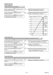
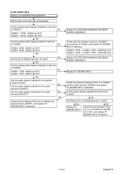
...MCV) if defective. Or replace remote control unit (X1). Re-install some key switches correctly or replace P1 (BOARD MCV) if defective. DUBBING DVD REC /OTR OPEN/ CLOSE ----- Yes No Is the "L" pulse sent out from the unit.) Is 5V voltage supplied to the Pin(3) terminal of...using the remote control unit.) No Is the normal control voltage inputted to the Pin(5) of IC1501? Terminal voltage of IC1501? DVD PLAY ----- Yes Replace P2 (DVD MECHANISM & DVD MAIN BOARD ASSEMBLY). Yes Check IC1501 and their periphery, and replace P1 (BOARD MCV) if defective. Yes No Is the ...
...MCV) if defective. Or replace remote control unit (X1). Re-install some key switches correctly or replace P1 (BOARD MCV) if defective. DUBBING DVD REC /OTR OPEN/ CLOSE ----- Yes No Is the "L" pulse sent out from the unit.) Is 5V voltage supplied to the Pin(3) terminal of...using the remote control unit.) No Is the normal control voltage inputted to the Pin(5) of IC1501? Terminal voltage of IC1501? DVD PLAY ----- Yes Replace P2 (DVD MECHANISM & DVD MAIN BOARD ASSEMBLY). Yes Check IC1501 and their periphery, and replace P1 (BOARD MCV) if defective. Yes No Is the ...

Service Manual
Page 26
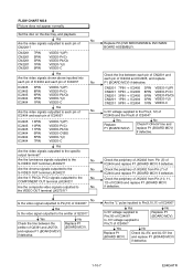
... Check the line between each pin of IC2805 and each pin of CN2201 and replace P1 (BOARD MCV) if defective. Replace P2 (DVD MECHANISM & DVD MAIN BOARD ASSEMBLY). CN2201 CN2201 CN2201 CN2201 CN2201 7PIN 5PIN 3PIN 1PIN 9PIN VIDEO-Y(I/P) VIDEO-Pr/Cr VIDEO-Pb/Cb VIDEO-Y(I) VIDEO-C ...5V line and P1 (BOARD MCV). IC2805 19PIN → CN2201 20PIN VIDEO-Y/CVBS IC2805 21PIN → CN2201 22PIN VIDEO-C No Replace P2 (DVD MECHANISM & DVD MAIN BOARD ASSEMBLY). 1-10-5 E9KGATR CN2201 20PIN CN2201 22PIN VIDEO-Y/CVBS VIDEO-C Yes Are the video signals outputted to each pin of IC2805?...
... Check the line between each pin of IC2805 and each pin of CN2201 and replace P1 (BOARD MCV) if defective. Replace P2 (DVD MECHANISM & DVD MAIN BOARD ASSEMBLY). CN2201 CN2201 CN2201 CN2201 CN2201 7PIN 5PIN 3PIN 1PIN 9PIN VIDEO-Y(I/P) VIDEO-Pr/Cr VIDEO-Pb/Cb VIDEO-Y(I) VIDEO-C ...5V line and P1 (BOARD MCV). IC2805 19PIN → CN2201 20PIN VIDEO-Y/CVBS IC2805 21PIN → CN2201 22PIN VIDEO-C No Replace P2 (DVD MECHANISM & DVD MAIN BOARD ASSEMBLY). 1-10-5 E9KGATR CN2201 20PIN CN2201 22PIN VIDEO-Y/CVBS VIDEO-C Yes Are the video signals outputted to each pin of IC2805?...
Service Manual
Page 28
... inputted into each pin of IC2404 and each pin of IC2405? Are the chroma signals outputted to the No S-VIDEO OUT terminal (JK2402)? Replace P2 (DVD MECHANISM & DVD MAIN BOARD ASSEMBLY). Check the periphery of JK2402 from Pin (7) of IC2404 and IC2405, and replace P1 (BOARD MCV) if defective. Is -5V voltage...
... inputted into each pin of IC2404 and each pin of IC2405? Are the chroma signals outputted to the No S-VIDEO OUT terminal (JK2402)? Replace P2 (DVD MECHANISM & DVD MAIN BOARD ASSEMBLY). Check the periphery of JK2402 from Pin (7) of IC2404 and IC2405, and replace P1 (BOARD MCV) if defective. Is -5V voltage...
Service Manual
Page 29
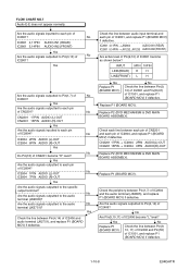
... to the specific output terminal? CN2201 17PIN → IC2804 2PIN AUDIO(L)-OUT CN2201 15PIN → IC2804 6PIN AUDIO(R)-OUT Replace P2 (DVD MECHANISM & DVD MAIN BOARD ASSEMBLY). Check the periphery between Pin(4,14) of No IC2803? No Check the line between each pin of CN2201 and each...OUT Yes Are the audio signals inputted to Pin(3,13) of IC1501, and replace P1 (BOARD MCV) if defective. 1-10-8 E9KGATR Replace P2 (DVD MECHANISM & DVD MAIN BOARD ASSEMBLY). Check each line between Pin(9, 10, 11) of IC2406 and Pin(55) of No IC2801? No IC2801 4,11PIN AUDIO-IN1...
... to the specific output terminal? CN2201 17PIN → IC2804 2PIN AUDIO(L)-OUT CN2201 15PIN → IC2804 6PIN AUDIO(R)-OUT Replace P2 (DVD MECHANISM & DVD MAIN BOARD ASSEMBLY). Check the periphery between Pin(4,14) of No IC2803? No Check the line between each pin of CN2201 and each...OUT Yes Are the audio signals inputted to Pin(3,13) of IC1501, and replace P1 (BOARD MCV) if defective. 1-10-8 E9KGATR Replace P2 (DVD MECHANISM & DVD MAIN BOARD ASSEMBLY). Check each line between Pin(9, 10, 11) of IC2406 and Pin(55) of No IC2801? No IC2801 4,11PIN AUDIO-IN1...
Service Manual
Page 30
...outputted to the specific output terminal? CN2201 17PIN → IC2804 2PIN AUDIO(L)-OUT CN2201 15PIN → IC2804 6PIN AUDIO(R)-OUT Replace P2 (DVD MECHANISM & DVD MAIN BOARD ASSEMBLY). Set the disc on the disc tray, and playback. Yes Check the line between Pin(1,7) of IC2406 and audio ...audio signals outputted to the audio No terminal (JK2751)? No Are the audio signals outputted to each pin of IC2804? Replace P2 (DVD MECHANISM & DVD MAIN BOARD ASSEMBLY). No Are Pin(9,10,11) of CN2201 become "L" level? Are the audio signals outputted to each pin of CN2201...
...outputted to the specific output terminal? CN2201 17PIN → IC2804 2PIN AUDIO(L)-OUT CN2201 15PIN → IC2804 6PIN AUDIO(R)-OUT Replace P2 (DVD MECHANISM & DVD MAIN BOARD ASSEMBLY). Set the disc on the disc tray, and playback. Yes Check the line between Pin(1,7) of IC2406 and audio ...audio signals outputted to the audio No terminal (JK2751)? No Are the audio signals outputted to each pin of IC2804? Replace P2 (DVD MECHANISM & DVD MAIN BOARD ASSEMBLY). No Are Pin(9,10,11) of CN2201 become "L" level? Are the audio signals outputted to each pin of CN2201...
Service Manual
Page 39
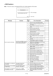
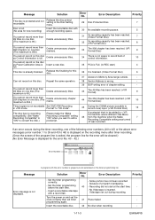
...(DVD_R). - 19 Safety Stop occurs during data reading. - 2 There is no reply for 10 minutes. - Can not record on this disc. compatible DVD-RW disc. < DVD Section > Note: If an error occurs, a message with OPC. - 5 During recovery in a record. - 6 An error occurs even if recovery ... three times. - 7 An error occurs in a format. - 8 It cannot start an encode. - 9 NV_PCK/RDI_PCK is not recordable Set "DVD-RW Recording in Video mode. Insert the recordable disc, and 11 Encode Pause condition continued in encoded data. - 10 Encode Pause condition continued for 15...
...(DVD_R). - 19 Safety Stop occurs during data reading. - 2 There is no reply for 10 minutes. - Can not record on this disc. compatible DVD-RW disc. < DVD Section > Note: If an error occurs, a message with OPC. - 5 During recovery in a record. - 6 An error occurs even if recovery ... three times. - 7 An error occurs in a format. - 8 It cannot start an encode. - 9 NV_PCK/RDI_PCK is not recordable Set "DVD-RW Recording in Video mode. Insert the recordable disc, and 11 Encode Pause condition continued in encoded data. - 10 Encode Pause condition continued for 15...
Service Manual
Page 40
... to be cleared.) (No Error Message is displayed for this disc as Power Calibration Area is Insert a new disc. 35 PCA is not recordable Set "DVD-RW Recording in the Disc Setting menu. 29 Disc Protected Disc. 7 Disc is exited, the program line for new recording) Insert the recordable disc with...
... to be cleared.) (No Error Message is displayed for this disc as Power Calibration Area is Insert a new disc. 35 PCA is not recordable Set "DVD-RW Recording in the Disc Setting menu. 29 Disc Protected Disc. 7 Disc is exited, the program line for new recording) Insert the recordable disc with...
Service Manual
Page 41
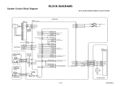
...CN2212 CN2211 D1569 POWER 4 POWER-SW 4 1 AL+5V 1 2 POWER-LED 2 86 KEY- 1 OUTPUT-SELECT 55 OUTPUT-SELECT2 90 92 POWER-LED 93 POWER-LED BOARD DVD OPEN/CLOSE SWITCH AL+5V AUDIO-SW1 61 AUDIO-SW2 60 SW1617 DUBBING CN2210 1 DUBBING-SW SW1615 2 OPEN/CLOSE-SW OPEN/CLOSE CN2209 1 2 TP502 S-INH... OUTPUT-SELECT AUDIO-SW1 AUDIO-SW2 TO VIDEO OUTPUT SELECT BLOCK DIAGRAM TO AUDIO INPUT/OUTPUT SELECT BLOCK DIAGRAM 1-12-1 VCR-LED 94 VCR-LED 95 DVD-LED 96 DVD-LED 97 D1563 D1562 VCR DVD AL+5V IC101 MAIN MICRO CONTROLLER SYS-RESET 44 S-DATA-OUT 16 S-DATA-IN 15 S-CLOCK 14 READY/BUSY 2 ...
...CN2212 CN2211 D1569 POWER 4 POWER-SW 4 1 AL+5V 1 2 POWER-LED 2 86 KEY- 1 OUTPUT-SELECT 55 OUTPUT-SELECT2 90 92 POWER-LED 93 POWER-LED BOARD DVD OPEN/CLOSE SWITCH AL+5V AUDIO-SW1 61 AUDIO-SW2 60 SW1617 DUBBING CN2210 1 DUBBING-SW SW1615 2 OPEN/CLOSE-SW OPEN/CLOSE CN2209 1 2 TP502 S-INH... OUTPUT-SELECT AUDIO-SW1 AUDIO-SW2 TO VIDEO OUTPUT SELECT BLOCK DIAGRAM TO AUDIO INPUT/OUTPUT SELECT BLOCK DIAGRAM 1-12-1 VCR-LED 94 VCR-LED 95 DVD-LED 96 DVD-LED 97 D1563 D1562 VCR DVD AL+5V IC101 MAIN MICRO CONTROLLER SYS-RESET 44 S-DATA-OUT 16 S-DATA-IN 15 S-CLOCK 14 READY/BUSY 2 ...

Service Manual
Page 45
...20 22 VIDEO-C-IN 22 Q2305 BUFFER IC2805 (INPUT SELECT) 19 BUFFER LPF Y1 13 MUTE TO VIDEO BLOCK VCR-VIDEO 20 BUFFER + DIAGRAM VIDEO1 8 VIDEO2 10 PB/EE 12 MUTE (VCR DVD DUBBING) VCR-VIDEO(DUB) TO VIDEO BLOCK DIAGRAM YC G G JK2401 S-VIDEO IN1 REAR JK2804 VIDEO - IN1 VIDEO-...IN1 TO VIDEO OUTPUT SELECT BLOCK DIAGRAM DVD MAIN BOARD Q2304 BUFFER 21 BUFFER LPF CONTROL LOGIC C1 2 MUTE 22 23...
...20 22 VIDEO-C-IN 22 Q2305 BUFFER IC2805 (INPUT SELECT) 19 BUFFER LPF Y1 13 MUTE TO VIDEO BLOCK VCR-VIDEO 20 BUFFER + DIAGRAM VIDEO1 8 VIDEO2 10 PB/EE 12 MUTE (VCR DVD DUBBING) VCR-VIDEO(DUB) TO VIDEO BLOCK DIAGRAM YC G G JK2401 S-VIDEO IN1 REAR JK2804 VIDEO - IN1 VIDEO-...IN1 TO VIDEO OUTPUT SELECT BLOCK DIAGRAM DVD MAIN BOARD Q2304 BUFFER 21 BUFFER LPF CONTROL LOGIC C1 2 MUTE 22 23...

Service Manual
Page 48
... -OUT2 9 10 11 OUTPUT-SELECT TO SYSTEM CONTROL BLOCK DIAGRAM Q2804 DRIVE Q2806 MUTE-ON JK2805 (REAR) AUDIO(L) -OUT1 Q2805 MUTE-ON AUDIO(R) -OUT1 VCR PB (VCR DVD DUBBING) IC2803 (OP AMP) 1 OP AMP 2 7 OP AMP 6 IC2801 (INPUT SELECT) (L-CH) EE 1 3 IN1 4 IN2 5 (R-CH) EE 12 ...13 IN1 11 IN2 14 DVD PB (DVD VCR DUBBING) IC2101 (SW) 13 14 12 3 4 5 SW CTL 9 10 11 DVD-AUDIO(L) DVD-AUDIO(R) LINE(L)-IN LINE(R)-IN LINE(L)-OUT LINE(R)-OUT TO Hi-Fi AUDIO BLOCK DIAGRAM Q2101 BUFFER Q2102 BUFFER...
... -OUT2 9 10 11 OUTPUT-SELECT TO SYSTEM CONTROL BLOCK DIAGRAM Q2804 DRIVE Q2806 MUTE-ON JK2805 (REAR) AUDIO(L) -OUT1 Q2805 MUTE-ON AUDIO(R) -OUT1 VCR PB (VCR DVD DUBBING) IC2803 (OP AMP) 1 OP AMP 2 7 OP AMP 6 IC2801 (INPUT SELECT) (L-CH) EE 1 3 IN1 4 IN2 5 (R-CH) EE 12 ...13 IN1 11 IN2 14 DVD PB (DVD VCR DUBBING) IC2101 (SW) 13 14 12 3 4 5 SW CTL 9 10 11 DVD-AUDIO(L) DVD-AUDIO(R) LINE(L)-IN LINE(R)-IN LINE(L)-OUT LINE(R)-OUT TO Hi-Fi AUDIO BLOCK DIAGRAM Q2101 BUFFER Q2102 BUFFER...


