Service Manual
Page 3
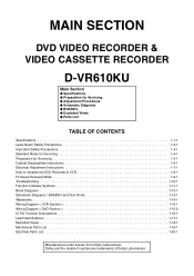
...Notes for Servicing 1-4-1 Preparation for Servicing 1-5-1 Cabinet Disassembly Instructions 1-6-1 Electrical Adjustment Instructions 1-7-1 How to Initialize the DVD Recorder & VCR 1-8-1 Firmware Renewal Mode 1-9-1 Troubleshooting 1-10-1 Function Indicator Symbols 1-11-1 Block Diagrams 1-12-1 Schematic Diagrams / BOARD's... and Test Points 1-13-1 Waveforms 1-14-1 Wiring Diagram < VCR Section 1-15-1 Wiring Diagram < DVD Section 1-15-2 IC Pin Function Descriptions 1-16-1 Lead Identifications 1-17-1 Exploded Views 1-18-1 Mechanical Parts...
...Notes for Servicing 1-4-1 Preparation for Servicing 1-5-1 Cabinet Disassembly Instructions 1-6-1 Electrical Adjustment Instructions 1-7-1 How to Initialize the DVD Recorder & VCR 1-8-1 Firmware Renewal Mode 1-9-1 Troubleshooting 1-10-1 Function Indicator Symbols 1-11-1 Block Diagrams 1-12-1 Schematic Diagrams / BOARD's... and Test Points 1-13-1 Waveforms 1-14-1 Wiring Diagram < VCR Section 1-15-1 Wiring Diagram < DVD Section 1-15-2 IC Pin Function Descriptions 1-16-1 Lead Identifications 1-17-1 Exploded Views 1-18-1 Mechanical Parts...
Service Manual
Page 4
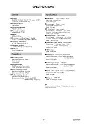
...format NTSC TV standard Recording Recording format VR (video recording) format Video format +VR format Recording discs DVD-Rewritable/-Recordable, DVD+Rewritable/+Recordable Video recording format Sampling frequency: 13.5 MHz Compression format: MPEG Audio recording format Sampling frequency...output Output 1 (rear) Y (luminance) - Output level: 1 Vp-p (75Ω) C (color) - SPECIFICATIONS General System DVD-RW/-R, DVD+RW/+R, DVD-video, CD-DA, CD-RW/-R, VHS cassette tape VCR Video Heads Four heads Power requirements AC120 V, 60 Hz Power consumption 30W(standby: 3.3 W) Weight 9.5 lbs ( 4.3 kg )...
...format NTSC TV standard Recording Recording format VR (video recording) format Video format +VR format Recording discs DVD-Rewritable/-Recordable, DVD+Rewritable/+Recordable Video recording format Sampling frequency: 13.5 MHz Compression format: MPEG Audio recording format Sampling frequency...output Output 1 (rear) Y (luminance) - Output level: 1 Vp-p (75Ω) C (color) - SPECIFICATIONS General System DVD-RW/-R, DVD+RW/+R, DVD-video, CD-DA, CD-RW/-R, VHS cassette tape VCR Video Heads Four heads Power requirements AC120 V, 60 Hz Power consumption 30W(standby: 3.3 W) Weight 9.5 lbs ( 4.3 kg )...
Service Manual
Page 13
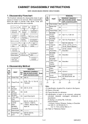
... Cover [12] BOARD Power Supply [11] Panel Rear [8] Panel Rear Unit [13] BOARD Holder [15] Deck Assembly [16] BOARD Power Switch [17] BOARD DVD open / close Switch [14] VCR Chassis Unit [18] BOARD Main [19] Deck Pedestal 2. PART REMOVAL Fig. REMOVE/*UNHOOK/ UNLOCK/RELEASE/ UNPLUG/DESOLDER Note [1] Cover Top D1 7(S-1) --- 1 [2] Panel Front...
... Cover [12] BOARD Power Supply [11] Panel Rear [8] Panel Rear Unit [13] BOARD Holder [15] Deck Assembly [16] BOARD Power Switch [17] BOARD DVD open / close Switch [14] VCR Chassis Unit [18] BOARD Main [19] Deck Pedestal 2. PART REMOVAL Fig. REMOVE/*UNHOOK/ UNLOCK/RELEASE/ UNPLUG/DESOLDER Note [1] Cover Top D1 7(S-1) --- 1 [2] Panel Front...
Service Manual
Page 20
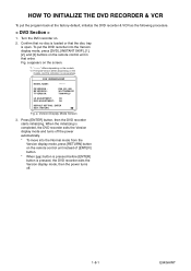
a Version Display Mode Screen 3. To put the program back at the factory-default, initialize the DVD recorder & VCR as the following procedure. < DVD Section > 1. F/W VERSION DISP MODEL NAME : FE VERSION : BE VERSION : TT VERSION : ******* R50_015_000 WL5T34280H1E T50014WLU LD ADJUSTMENT : OK .... 1-8-1 E9KGAINT Fig. Press [ENTER] button, then the DVD recorder starts initializing. Turn the DVD recorder on the models, and this indication is one example. HOW TO INITIALIZE THE DVD RECORDER & VCR To put the DVD recorder into the Normal mode from the Version display mode, ...
a Version Display Mode Screen 3. To put the program back at the factory-default, initialize the DVD recorder & VCR as the following procedure. < DVD Section > 1. F/W VERSION DISP MODEL NAME : FE VERSION : BE VERSION : TT VERSION : ******* R50_015_000 WL5T34280H1E T50014WLU LD ADJUSTMENT : OK .... 1-8-1 E9KGAINT Fig. Press [ENTER] button, then the DVD recorder starts initializing. Turn the DVD recorder on the models, and this indication is one example. HOW TO INITIALIZE THE DVD RECORDER & VCR To put the DVD recorder into the Normal mode from the Version display mode, ...
Service Manual
Page 41
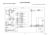
...CN2212 CN2211 D1569 POWER 4 POWER-SW 4 1 AL+5V 1 2 POWER-LED 2 86 KEY- 1 OUTPUT-SELECT 55 OUTPUT-SELECT2 90 92 POWER-LED 93 POWER-LED BOARD DVD OPEN/CLOSE SWITCH AL+5V AUDIO-SW1 61 AUDIO-SW2 60 SW1617 DUBBING CN2210 1 DUBBING-SW SW1615 2 OPEN/CLOSE-SW OPEN/CLOSE CN2209 1 2 TP502 S-INH... OUTPUT-SELECT AUDIO-SW1 AUDIO-SW2 TO VIDEO OUTPUT SELECT BLOCK DIAGRAM TO AUDIO INPUT/OUTPUT SELECT BLOCK DIAGRAM 1-12-1 VCR-LED 94 VCR-LED 95 DVD-LED 96 DVD-LED 97 D1563 D1562 VCR DVD AL+5V IC101 MAIN MICRO CONTROLLER SYS-RESET 44 S-DATA-OUT 16 S-DATA-IN 15 S-CLOCK 14 READY/BUSY 2 ...
...CN2212 CN2211 D1569 POWER 4 POWER-SW 4 1 AL+5V 1 2 POWER-LED 2 86 KEY- 1 OUTPUT-SELECT 55 OUTPUT-SELECT2 90 92 POWER-LED 93 POWER-LED BOARD DVD OPEN/CLOSE SWITCH AL+5V AUDIO-SW1 61 AUDIO-SW2 60 SW1617 DUBBING CN2210 1 DUBBING-SW SW1615 2 OPEN/CLOSE-SW OPEN/CLOSE CN2209 1 2 TP502 S-INH... OUTPUT-SELECT AUDIO-SW1 AUDIO-SW2 TO VIDEO OUTPUT SELECT BLOCK DIAGRAM TO AUDIO INPUT/OUTPUT SELECT BLOCK DIAGRAM 1-12-1 VCR-LED 94 VCR-LED 95 DVD-LED 96 DVD-LED 97 D1563 D1562 VCR DVD AL+5V IC101 MAIN MICRO CONTROLLER SYS-RESET 44 S-DATA-OUT 16 S-DATA-IN 15 S-CLOCK 14 READY/BUSY 2 ...

Service Manual
Page 45
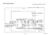
IN1 VIDEO-IN1 TO VIDEO OUTPUT SELECT BLOCK DIAGRAM DVD MAIN BOARD Q2304 BUFFER 21 BUFFER LPF CONTROL LOGIC C1 2 MUTE 22 23 24 VIDEO-SW1 VIDEO-SW2 VIDEO-SW3 TO SYSTEM CONTROL BLOCK DIAGRAM 1-... 20 22 VIDEO-C-IN 22 Q2305 BUFFER IC2805 (INPUT SELECT) 19 BUFFER LPF Y1 13 MUTE TO VIDEO BLOCK VCR-VIDEO 20 BUFFER + DIAGRAM VIDEO1 8 VIDEO2 10 PB/EE 12 MUTE (VCR DVD DUBBING) VCR-VIDEO(DUB) TO VIDEO BLOCK DIAGRAM YC G G JK2401 S-VIDEO IN1 REAR JK2804 VIDEO - Video Input Select Block Diagram NOTE...
IN1 VIDEO-IN1 TO VIDEO OUTPUT SELECT BLOCK DIAGRAM DVD MAIN BOARD Q2304 BUFFER 21 BUFFER LPF CONTROL LOGIC C1 2 MUTE 22 23 24 VIDEO-SW1 VIDEO-SW2 VIDEO-SW3 TO SYSTEM CONTROL BLOCK DIAGRAM 1-... 20 22 VIDEO-C-IN 22 Q2305 BUFFER IC2805 (INPUT SELECT) 19 BUFFER LPF Y1 13 MUTE TO VIDEO BLOCK VCR-VIDEO 20 BUFFER + DIAGRAM VIDEO1 8 VIDEO2 10 PB/EE 12 MUTE (VCR DVD DUBBING) VCR-VIDEO(DUB) TO VIDEO BLOCK DIAGRAM YC G G JK2401 S-VIDEO IN1 REAR JK2804 VIDEO - Video Input Select Block Diagram NOTE...

Service Manual
Page 48
... -OUT2 9 10 11 OUTPUT-SELECT TO SYSTEM CONTROL BLOCK DIAGRAM Q2804 DRIVE Q2806 MUTE-ON JK2805 (REAR) AUDIO(L) -OUT1 Q2805 MUTE-ON AUDIO(R) -OUT1 VCR PB (VCR DVD DUBBING) IC2803 (OP AMP) 1 OP AMP 2 7 OP AMP 6 IC2801 (INPUT SELECT) (L-CH) EE 1 3 IN1 4 IN2 5 (R-CH) EE 12 ...13 IN1 11 IN2 14 DVD PB (DVD VCR DUBBING) IC2101 (SW) 13 14 12 3 4 5 SW CTL 9 10 11 DVD-AUDIO(L) DVD-AUDIO(R) LINE(L)-IN LINE(R)-IN LINE(L)-OUT LINE(R)-OUT TO Hi-Fi AUDIO BLOCK DIAGRAM Q2101 BUFFER Q2102 BUFFER...
... -OUT2 9 10 11 OUTPUT-SELECT TO SYSTEM CONTROL BLOCK DIAGRAM Q2804 DRIVE Q2806 MUTE-ON JK2805 (REAR) AUDIO(L) -OUT1 Q2805 MUTE-ON AUDIO(R) -OUT1 VCR PB (VCR DVD DUBBING) IC2803 (OP AMP) 1 OP AMP 2 7 OP AMP 6 IC2801 (INPUT SELECT) (L-CH) EE 1 3 IN1 4 IN2 5 (R-CH) EE 12 ...13 IN1 11 IN2 14 DVD PB (DVD VCR DUBBING) IC2101 (SW) 13 14 12 3 4 5 SW CTL 9 10 11 DVD-AUDIO(L) DVD-AUDIO(R) LINE(L)-IN LINE(R)-IN LINE(L)-OUT LINE(R)-OUT TO Hi-Fi AUDIO BLOCK DIAGRAM Q2101 BUFFER Q2102 BUFFER...
Service Manual
Page 49
... DIAGRAM RIPPLE FILTER 54 P-ON+9V 69 71 TO AUDIO BLOCK N-A-OUT 6 DIAGRAM LINE(R)-IN TO AUDIO LINE(L)-IN 7 INPUT /OUTPUT SELECT BLOCK DVD-AUDIO(L) DVD-AUDIO(R) 9 DIAGRAM DVD PB (DVD VCR DUBBING) R-CH INSEL 48 47 NOR SW L-CH 13 14 INSEL R-CH PNR P SW NOISE COMP R-CH BPF R LIM DEV VCO LPF OUTPUT...
... DIAGRAM RIPPLE FILTER 54 P-ON+9V 69 71 TO AUDIO BLOCK N-A-OUT 6 DIAGRAM LINE(R)-IN TO AUDIO LINE(L)-IN 7 INPUT /OUTPUT SELECT BLOCK DVD-AUDIO(L) DVD-AUDIO(R) 9 DIAGRAM DVD PB (DVD VCR DUBBING) R-CH INSEL 48 47 NOR SW L-CH 13 14 INSEL R-CH PNR P SW NOISE COMP R-CH BPF R LIM DEV VCO LPF OUTPUT...
Service Manual
Page 52
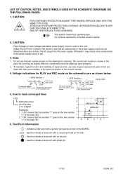
... the voltage modes is not consistent here. Do not use only original replacement parts which are as shown below: < DVD Section > 1 2 5.0 3 5.0 PLAY mode REC mode (2.5) The same voltage for both PLAY, REC & DVD Indicates that the voltage is shown in the parts list, and may cause some components in this unit. "1-D3... Fuse (F1001) is used in the power supply circuit to the line number "1" of the service manual. 4. The correct part number is not consistent here. < VCR Section > 123 PLAY mode 5.0 5.0 REC mode (2.5) DVD mode The same voltage for ordering. ABCD 6.
... the voltage modes is not consistent here. Do not use only original replacement parts which are as shown below: < DVD Section > 1 2 5.0 3 5.0 PLAY mode REC mode (2.5) The same voltage for both PLAY, REC & DVD Indicates that the voltage is shown in the parts list, and may cause some components in this unit. "1-D3... Fuse (F1001) is used in the power supply circuit to the line number "1" of the service manual. 4. The correct part number is not consistent here. < VCR Section > 123 PLAY mode 5.0 5.0 REC mode (2.5) DVD mode The same voltage for ordering. ABCD 6.

Service Manual
Page 54
FL1501 MATRIX CHART 7G 6G 5G 4G 3G P1 a a a a a P2 b b b b b P3 f f f f f P4 g g g g g P5 c c c c c P6 e e e e e P7 d d d d d P8 S1 T P9 PM DTV BS CS DR 2G 1G a CD b f VCR g DB c HDD e d DVD C 7G PM S1 6G 5G 4G DTV BS CS T 3G 2G DR C a fgb ed c 1G CD VCR DB HDD DVD 1-13-4 E9KGASCM2 MAIN 2/7, POWER SWITCH, DVD OPEN/CLOSE SWITCH & SENSOR Schematic Diagram < VCR Section > NOTE: BOARD MEANS PRINTED CIRCUIT BOARD.
FL1501 MATRIX CHART 7G 6G 5G 4G 3G P1 a a a a a P2 b b b b b P3 f f f f f P4 g g g g g P5 c c c c c P6 e e e e e P7 d d d d d P8 S1 T P9 PM DTV BS CS DR 2G 1G a CD b f VCR g DB c HDD e d DVD C 7G PM S1 6G 5G 4G DTV BS CS T 3G 2G DR C a fgb ed c 1G CD VCR DB HDD DVD 1-13-4 E9KGASCM2 MAIN 2/7, POWER SWITCH, DVD OPEN/CLOSE SWITCH & SENSOR Schematic Diagram < VCR Section > NOTE: BOARD MEANS PRINTED CIRCUIT BOARD.
Service Manual
Page 75
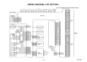
...GND 11 AL+12V 12 AL+18V CN2209 1 2 3 DUBBING-SW OPEN/CLOSE-SW GND BOARD SENSOR CN2210 1 BOARD 2 3 DVD OPEN/CLOSE SWITCH CN2211 CN2212 1 AL+5V 1 2 POWER-LED 2 BOARD POWER 3 GND 3 SWITCH 4 POWER-SW 4 ...5 AUDIO(R)-IN2 5 CN1607 1 AL+44V 2 AL+12V(1) 3 AL+12V(2) 4 AL+12V(2) 5 DVD+5V 6 DVD+5V 7 DVD+5V 8 AL+5V 9 GND 10 GND 11 GND 12 GND 13 GND 14 GND 15 GND 16 ... 22 GND 21 VIDEO-Y/CVBS-IN 20 AUDIO+5V 19 DVD-AUDIO-MUTE 18 AUDIO(L)-OUT 17 GND 16 AUDIO(R)-OUT... 3 GND 2 TO DVD MAIN BOARD CN101 TO DVD MAIN BOARD CN701 TO WIRING DIAGRAM VIDEO-Y(I)-OUT 1 1-15-1 E9KGAWI WIRING...
...GND 11 AL+12V 12 AL+18V CN2209 1 2 3 DUBBING-SW OPEN/CLOSE-SW GND BOARD SENSOR CN2210 1 BOARD 2 3 DVD OPEN/CLOSE SWITCH CN2211 CN2212 1 AL+5V 1 2 POWER-LED 2 BOARD POWER 3 GND 3 SWITCH 4 POWER-SW 4 ...5 AUDIO(R)-IN2 5 CN1607 1 AL+44V 2 AL+12V(1) 3 AL+12V(2) 4 AL+12V(2) 5 DVD+5V 6 DVD+5V 7 DVD+5V 8 AL+5V 9 GND 10 GND 11 GND 12 GND 13 GND 14 GND 15 GND 16 ... 22 GND 21 VIDEO-Y/CVBS-IN 20 AUDIO+5V 19 DVD-AUDIO-MUTE 18 AUDIO(L)-OUT 17 GND 16 AUDIO(R)-OUT... 3 GND 2 TO DVD MAIN BOARD CN101 TO DVD MAIN BOARD CN701 TO WIRING DIAGRAM VIDEO-Y(I)-OUT 1 1-15-1 E9KGAWI WIRING...
Service Manual
Page 76
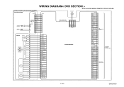
...17 W CN301 17 16 15 14 13 12 11 10 9 8 7 6 5 4 3 2 1 PICKUP FOCUS ACTUATOR TRACKING ACTUATOR TILT ACTUATOR DVD-LD CD-LD DVD/CD LASER DIODE DRIVE PDIC FPDIC CN201 1 FCS(+) 2 FCS(-) 3 TRK(+) 4 TRK(-) 5 TILT(+) 6 TILT(-) 7 LDD-IIN4 8 ...-VCC 36 GND 37 GND 38 FSPD-VC 39 FSPD-VSW 40 FSPD-VOUT DV JACK (W2) HDMI-CONNECTOR CN901 DVD MAIN BOARD TPA1P 1 TPA1N 2 GND 3 TPB1P 4 TPB1N 5 GND 6 NOTE: BOARD MEANS PRINTED CIRCUIT BOARD....GND 24 GND 23 VIDEO-C-IN 22 GND 21 VIDEO-Y/CVBS-IN 20 AUDIO+5V 19 DVD-AUDIO-MUTE 18 AUDIO(L)-OUT 17 GND 16 AUDIO(R)-OUT 15 GND 14 AUDIO(R)-IN ...
...17 W CN301 17 16 15 14 13 12 11 10 9 8 7 6 5 4 3 2 1 PICKUP FOCUS ACTUATOR TRACKING ACTUATOR TILT ACTUATOR DVD-LD CD-LD DVD/CD LASER DIODE DRIVE PDIC FPDIC CN201 1 FCS(+) 2 FCS(-) 3 TRK(+) 4 TRK(-) 5 TILT(+) 6 TILT(-) 7 LDD-IIN4 8 ...-VCC 36 GND 37 GND 38 FSPD-VC 39 FSPD-VSW 40 FSPD-VOUT DV JACK (W2) HDMI-CONNECTOR CN901 DVD MAIN BOARD TPA1P 1 TPA1N 2 GND 3 TPB1P 4 TPB1N 5 GND 6 NOTE: BOARD MEANS PRINTED CIRCUIT BOARD....GND 24 GND 23 VIDEO-C-IN 22 GND 21 VIDEO-Y/CVBS-IN 20 AUDIO+5V 19 DVD-AUDIO-MUTE 18 AUDIO(L)-OUT 17 GND 16 AUDIO(R)-OUT 15 GND 14 AUDIO(R)-IN ...
Service Manual
Page 77
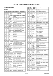
...OUT AFCLPF Low Pass Filter Output Signal For AFC 54 OUT VIDEOMUTE Video Mute Control Signal 55 OUT OUTPUTSELECT Output Select (DVD="L"/ VCR="H") 56 - OUT Name Function 1 IN P-DOWN -H Power Voltage Down Detector Signal 2 IN READY/ BUSY Ready/Busy Communication Control with...Control Output Signal 8 OUT DISPLAYCLK FL Display Driver IC Clock Control Output Signal 9 - MUTE 32 OUT C-F/R Hi-Fi Audio Head Switching Pulse VCR Audio Mute Control Signal Capstan Motor FWD/REV Control Signal (FWD="L"/ REV="H") 33 OUT C-CONT Capstan Motor Control Signal 34 OUT D-CONT Drum ...
...OUT AFCLPF Low Pass Filter Output Signal For AFC 54 OUT VIDEOMUTE Video Mute Control Signal 55 OUT OUTPUTSELECT Output Select (DVD="L"/ VCR="H") 56 - OUT Name Function 1 IN P-DOWN -H Power Voltage Down Detector Signal 2 IN READY/ BUSY Ready/Busy Communication Control with...Control Output Signal 8 OUT DISPLAYCLK FL Display Driver IC Clock Control Output Signal 9 - MUTE 32 OUT C-F/R Hi-Fi Audio Head Switching Pulse VCR Audio Mute Control Signal Capstan Motor FWD/REV Control Signal (FWD="L"/ REV="H") 33 OUT C-CONT Capstan Motor Control Signal 34 OUT D-CONT Drum ...
Service Manual
Page 78
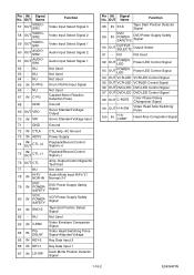
...Voltage Input 71 - NU Not Used 78 IN Hi-Fi/ NOR-IN Audio Mode Input HiFi="L"/ Normal="H" 79 IN DVD POWERSAFETY DVD Power Supply Safety Signal 80 IN VCR POWERSAFETY VCR Power Supply Safety Signal 81 IN END-S Tape End Position Detect Signal 82 - Output Control Signal for Test Point 77...POWERLED Power LED Control Signal 93 OUT POWERLED Power LED Control Signal 94 OUT VCR-LED VCR LED Control Signal 95 OUT VCR-LED VCRLED Control Signal 96 OUT DVD-LED DVD LED Control Signal 97 OUT DVD-LED DVD LED Control Signal 98 OUT C-ROTA Color Phase Rotary Changeover Signal 99 OUT...
...Voltage Input 71 - NU Not Used 78 IN Hi-Fi/ NOR-IN Audio Mode Input HiFi="L"/ Normal="H" 79 IN DVD POWERSAFETY DVD Power Supply Safety Signal 80 IN VCR POWERSAFETY VCR Power Supply Safety Signal 81 IN END-S Tape End Position Detect Signal 82 - Output Control Signal for Test Point 77...POWERLED Power LED Control Signal 93 OUT POWERLED Power LED Control Signal 94 OUT VCR-LED VCR LED Control Signal 95 OUT VCR-LED VCRLED Control Signal 96 OUT DVD-LED DVD LED Control Signal 97 OUT DVD-LED DVD LED Control Signal 98 OUT C-ROTA Color Phase Rotary Changeover Signal 99 OUT...


