Maintenance Manual
Page 4
... Replaceable Units (FRUs) and replace them in this manual. Installation of these messages will be sure to use only the same model battery or an equivalent battery recommended by Toshiba. iv Satellite A100/A105 / TECRA A7 Maintenance Manual SAFETY PRECAUTIONS Four types of messages are adhered to fasten screws securely with the right screwdriver. NOTE...
... Replaceable Units (FRUs) and replace them in this manual. Installation of these messages will be sure to use only the same model battery or an equivalent battery recommended by Toshiba. iv Satellite A100/A105 / TECRA A7 Maintenance Manual SAFETY PRECAUTIONS Four types of messages are adhered to fasten screws securely with the right screwdriver. NOTE...
Maintenance Manual
Page 7
... Battery 20 1.1.2 Battery Charging Control 20 1.1.3 RTC Battery 21 Chapter 2 Troubleshooting 2.1 Outline ...2-1 2.2 Basic Flowchart...2-2 2.3 Power Supply...2-6 Procedure 1 Power Icon Check 2-6 Procedure 2 Connection Check 2-8 Procedure 3 Replacement Check 2-8 2.4 System Board...2-9 Procedure 3 Replacement Check 2-10 2.5 2.5-inch HDD ...2-11 Procedure 1 Message Check 2-11 Procedure 2 Partition Check 2-11 Procedure 3 Format Check 2-12 Procedure 4 Test Program Check 2-13 Satellite A100/A105...
... Battery 20 1.1.2 Battery Charging Control 20 1.1.3 RTC Battery 21 Chapter 2 Troubleshooting 2.1 Outline ...2-1 2.2 Basic Flowchart...2-2 2.3 Power Supply...2-6 Procedure 1 Power Icon Check 2-6 Procedure 2 Connection Check 2-8 Procedure 3 Replacement Check 2-8 2.4 System Board...2-9 Procedure 3 Replacement Check 2-10 2.5 2.5-inch HDD ...2-11 Procedure 1 Message Check 2-11 Procedure 2 Partition Check 2-11 Procedure 3 Format Check 2-12 Procedure 4 Test Program Check 2-13 Satellite A100/A105...
Maintenance Manual
Page 11
... Procedures 4-5 Tools and Equipment 4-6 Screw Tightening Torque 4-6 Colors of Screw Shanks 4-7 Symbols of Screws on the Computer Body 4-7 Symbol examples 4-7 Removing the Battery Pack 4-8 Installing the Battery Pack 4-9 Removing the PCI Expresss Card 4-10 Installing the PCI Expresss Card 4-11 Removing the Optional PC Card 4-12 Installing the Optional PC Card...22 Installing the HDD 4-24 4.3 Speaker Cover and Keyboard 4-24 Removing the Speaker Cover and Keyboard 4-25 Installing the Speaker Cover and Keyboard 4-26 Satellite A100/A105 / TECRA A7 Maintenance Manual xi
... Procedures 4-5 Tools and Equipment 4-6 Screw Tightening Torque 4-6 Colors of Screw Shanks 4-7 Symbols of Screws on the Computer Body 4-7 Symbol examples 4-7 Removing the Battery Pack 4-8 Installing the Battery Pack 4-9 Removing the PCI Expresss Card 4-10 Installing the PCI Expresss Card 4-11 Removing the Optional PC Card 4-12 Installing the Optional PC Card...22 Installing the HDD 4-24 4.3 Speaker Cover and Keyboard 4-24 Removing the Speaker Cover and Keyboard 4-25 Installing the Speaker Cover and Keyboard 4-26 Satellite A100/A105 / TECRA A7 Maintenance Manual xi
Maintenance Manual
Page 17
1 Hardware Overview Chapter 1 Contents 1.1 Features...1 1.2 System Unit Components...9 1.3 2.5-inch HDD...15 1.4 DVD-ROM Drive...16 1.5 CD-RW/DVD-ROM Drive 17 1.6 DVD Super Multi (+-R Double Layer 18 1.7 Power Supply ...19 1.8 Batteries ...20 1.1.1 Main Battery 20 1.1.2 Battery Charging Control 20 1.1.3 RTC Battery 21 Satellite A100/A105 / TECRA A7 Maintenance Manual iii
1 Hardware Overview Chapter 1 Contents 1.1 Features...1 1.2 System Unit Components...9 1.3 2.5-inch HDD...15 1.4 DVD-ROM Drive...16 1.5 CD-RW/DVD-ROM Drive 17 1.6 DVD Super Multi (+-R Double Layer 18 1.7 Power Supply ...19 1.8 Batteries ...20 1.1.1 Main Battery 20 1.1.2 Battery Charging Control 20 1.1.3 RTC Battery 21 Satellite A100/A105 / TECRA A7 Maintenance Manual iii

Maintenance Manual
Page 18
... 15 Table 1- 2 DVD-ROM drive specifications 16 Table 1- 3 CD-RW/DVD-ROM drive specifications 17 Table 1- 4 DVD Super Multi drive (+-R Double Layer) specifications 18 Table 1- 5 Battery specifications 20 Table 1-6 Quick/normal charging time 21 iv Satellite A100/A105 / TECRA A7 Maintenance Manual
... 15 Table 1- 2 DVD-ROM drive specifications 16 Table 1- 3 CD-RW/DVD-ROM drive specifications 17 Table 1- 4 DVD Super Multi drive (+-R Double Layer) specifications 18 Table 1- 5 Battery specifications 20 Table 1-6 Quick/normal charging time 21 iv Satellite A100/A105 / TECRA A7 Maintenance Manual
Maintenance Manual
Page 19
...?512 MB (32M? 16? 8P)/533/667 MHZ ? 1024 MB (64Mx16x8P)/533/667 MHZ ? 1.1 Features 1 Hardware Overview 1.1 Features The Toshiba Satellite A100/A105 / TECRA A7 is the Intel Yonah Processor and Intel Yonah based Celeron M. Processor The CPU is a full size notebook PC based on the Intel... LCD panel, at 1.8 V, accepting BTO/CTO for your needs. It can be battery-operated for the CPU so that allows it to be designed to 4 GB of the following storage capacities: Satellite A100/A105 / TECRA A7 Maintenance Manual 1 using the following features. ? Host bridge system controller ...
...?512 MB (32M? 16? 8P)/533/667 MHZ ? 1024 MB (64Mx16x8P)/533/667 MHZ ? 1.1 Features 1 Hardware Overview 1.1 Features The Toshiba Satellite A100/A105 / TECRA A7 is the Intel Yonah Processor and Intel Yonah based Celeron M. Processor The CPU is a full size notebook PC based on the Intel... LCD panel, at 1.8 V, accepting BTO/CTO for your needs. It can be battery-operated for the CPU so that allows it to be designed to 4 GB of the following storage capacities: Satellite A100/A105 / TECRA A7 Maintenance Manual 1 using the following features. ? Host bridge system controller ...
Maintenance Manual
Page 20
...The serial data transfer rate is supported to daisy-chain a maximum of 127 USB devices. Batteries The computer has a removable 6/9/12 Cell Lithium Ion battery pack and an internal RTC battery (rechargeable). ? Keyboard The keyboard has 29 kinds countries key. ? ODD The ODD ... External monitor port A 15-pin external monitor port is provided, through which the computer automatically recognizes an external VESA DDC 2B compatible monitor. 2 Satellite A100/A105 / TECRA A7 Maintenance Manual 1 Hardware Overview 1.1 Features ? 40 GB (9.5 mm thick) SATA (5,400rpm) ? 60 GB (9.5 mm thick) ...
...The serial data transfer rate is supported to daisy-chain a maximum of 127 USB devices. Batteries The computer has a removable 6/9/12 Cell Lithium Ion battery pack and an internal RTC battery (rechargeable). ? Keyboard The keyboard has 29 kinds countries key. ? ODD The ODD ... External monitor port A 15-pin external monitor port is provided, through which the computer automatically recognizes an external VESA DDC 2B compatible monitor. 2 Satellite A100/A105 / TECRA A7 Maintenance Manual 1 Hardware Overview 1.1 Features ? 40 GB (9.5 mm thick) SATA (5,400rpm) ? 60 GB (9.5 mm thick) ...
Maintenance Manual
Page 31
...chip is used to serve as KBC/ EC and Super IO. ? EC access interface ? Clock Generator ? Modem Controller ?Built-in the battery pack ? Ring wake-up support ? KBC ? Overheat shutdown support ? Beep control ? I2C communication control ? ? ICS9LP306 ? Communication codes...For data communication: V.90(China)/V.92 data rates: 28kbps/56kbps V.34 Extended rates: 33.6K/2400/V.32 turbo, V.32bits,and fallbacks Satellite A100/A105 / TECRA A7 Maintenance Manual 13 Interface controller function ? Cooling fan speed control ? Device ON/OFF ? 1.2 System Unit Components 1 ...
...chip is used to serve as KBC/ EC and Super IO. ? EC access interface ? Clock Generator ? Modem Controller ?Built-in the battery pack ? Ring wake-up support ? KBC ? Overheat shutdown support ? Beep control ? I2C communication control ? ? ICS9LP306 ? Communication codes...For data communication: V.90(China)/V.92 data rates: 28kbps/56kbps V.34 Extended rates: 33.6K/2400/V.32 turbo, V.32bits,and fallbacks Satellite A100/A105 / TECRA A7 Maintenance Manual 13 Interface controller function ? Cooling fan speed control ? Device ON/OFF ? 1.2 System Unit Components 1 ...
Maintenance Manual
Page 37
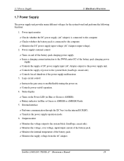
...load/logic circuit side). ?Monitors the voltage, over voltage, input/output current of the battery pack charging power supply. ? Instructs the gate array to the system block (load/logic circuit side). ? Battery indicator (in Blue or Green or AMBER). ? Controls forced shutdown if the power supply... AC adapter. Logic circuit control ? Performs communication through the I2C bus (via the internal EC/KBC). ? Status display ? Satellite A100/A105 / TECRA A7 Maintenance Manual 19 Checks whether the DC power supply (AC adapter) is connected to the computer. ?Checks whether the...
...load/logic circuit side). ?Monitors the voltage, over voltage, input/output current of the battery pack charging power supply. ? Instructs the gate array to the system block (load/logic circuit side). ? Battery indicator (in Blue or Green or AMBER). ? Controls forced shutdown if the power supply... AC adapter. Logic circuit control ? Performs communication through the I2C bus (via the internal EC/KBC). ? Status display ? Satellite A100/A105 / TECRA A7 Maintenance Manual 19 Checks whether the DC power supply (AC adapter) is connected to the computer. ?Checks whether the...
Maintenance Manual
Page 38
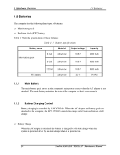
... computer, the LPC 47N249 controls the charge on/off or by on . 20 Satellite A100/A105 / TECRA A7 Maintenance Manual Main battery pack ? 1 Hardware Overview 1.8 Batteries 1.8 Batteries The computer has the following three types of these batteries. Table 1- 5 Battery specifications Battery name Material Output voltage Main battery pack 6 Cell Lithium Ion 9 Cell Lithium Ion 10.8 V 10.8 V Capacity 4000 mAh...
... computer, the LPC 47N249 controls the charge on/off or by on . 20 Satellite A100/A105 / TECRA A7 Maintenance Manual Main battery pack ? 1 Hardware Overview 1.8 Batteries 1.8 Batteries The computer has the following three types of these batteries. Table 1- 5 Battery specifications Battery name Material Output voltage Main battery pack 6 Cell Lithium Ion 9 Cell Lithium Ion 10.8 V 10.8 V Capacity 4000 mAh...
Maintenance Manual
Page 39
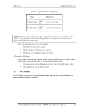
... circuit drops below the predetermined value. 2. Detection of full charge A full charge is detected only when the battery is met: 1. Satellite A100/A105 / Satellite Pro A100 / EQUIUM A100 Maintenance Manual 21 1.8 Batteries 1 Hardware Overview Table 1-6 Quick/normal charging time State Charge time Off-state charge 6/9/12 Cell About 4 hours max On-state charge 6/9/12 Cell...
... circuit drops below the predetermined value. 2. Detection of full charge A full charge is detected only when the battery is met: 1. Satellite A100/A105 / Satellite Pro A100 / EQUIUM A100 Maintenance Manual 21 1.8 Batteries 1 Hardware Overview Table 1-6 Quick/normal charging time State Charge time Off-state charge 6/9/12 Cell About 4 hours max On-state charge 6/9/12 Cell...

Maintenance Manual
Page 46
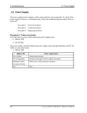
... Touch with Tomorrow Toshiba" displayed Yes Follow the system board diagnostic procedure in Section 2.4 No Follow the display diagnostic procedure in Section 2.3 Any error message displayed ?? Yes Turn the power on ?? Yes 1 Figure 2-1 Follow the HDD diagnostic procedure in Section 2.5 No Basic flowchart(1/2) Satellite A100/A105 / TECRA A7 Maintenance Manual 2-3 Yes BATTERY LED on ??
... Touch with Tomorrow Toshiba" displayed Yes Follow the system board diagnostic procedure in Section 2.4 No Follow the display diagnostic procedure in Section 2.3 Any error message displayed ?? Yes Turn the power on ?? Yes 1 Figure 2-1 Follow the HDD diagnostic procedure in Section 2.5 No Basic flowchart(1/2) Satellite A100/A105 / TECRA A7 Maintenance Manual 2-3 Yes BATTERY LED on ??
Maintenance Manual
Page 49
... in Green/Blue Blinking in the tables below as in Amber (at equal intervals) Off Power supply status Battery being charged Battery fully charged, with AC adapter connected Battery low *1 while driving the computer Else 2-6 Satellite A100/A105 / TECRA A7 Maintenance Manual 2 Troubleshooting 2.3 Power Supply 2.3 Power Supply The power supply in the computer controls many...
... in Green/Blue Blinking in the tables below as in Amber (at equal intervals) Off Power supply status Battery being charged Battery fully charged, with AC adapter connected Battery low *1 while driving the computer Else 2-6 Satellite A100/A105 / TECRA A7 Maintenance Manual 2 Troubleshooting 2.3 Power Supply 2.3 Power Supply The power supply in the computer controls many...
Maintenance Manual
Page 50
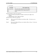
... again. If it does not, go to Procedure 3. Satellite A100/A105 / TECRA A7 Maintenance Manual 2-7 Else If the DC IN LED off , follow the steps below : Check 1 Make sure the DC IN LED goes on in Amber or Blue or Green . Remove the battery pack and the AC adapter to shut off power... to Procedure 2. DC IN LED DC IN LED On in Green/Blue Off Off Power supply status DC power being supplied (from the AC adapter) Battery damage and can't charge during DC-in Green or Blue . If it does not, go to the computer. 2. 2.3 Power Supply 2 Troubleshooting ? If the LED still...
... again. If it does not, go to Procedure 3. Satellite A100/A105 / TECRA A7 Maintenance Manual 2-7 Else If the DC IN LED off , follow the steps below : Check 1 Make sure the DC IN LED goes on in Amber or Blue or Green . Remove the battery pack and the AC adapter to shut off power... to Procedure 2. DC IN LED DC IN LED On in Green/Blue Off Off Power supply status DC power being supplied (from the AC adapter) Battery damage and can't charge during DC-in Green or Blue . If it does not, go to the computer. 2. 2.3 Power Supply 2 Troubleshooting ? If the LED still...

Maintenance Manual
Page 51
...2 Replace the system board with a new one . If the battery LED does not go on while the battery pack has been installed correctly, go on , perform Check 3. Check 3 Replace the CPU with a new one . 2-8 Satellite A100/A105 / TECRA A7 Maintenance Manual When they have been firmly plugged into ...the DC IN 19V socket and wall outlet, respectively. If the DC IN LED does not go to Procedure 3. ? If the battery pack is still not working properly, perform Check...
...2 Replace the system board with a new one . If the battery LED does not go on while the battery pack has been installed correctly, go on , perform Check 3. Check 3 Replace the CPU with a new one . 2-8 Satellite A100/A105 / TECRA A7 Maintenance Manual When they have been firmly plugged into ...the DC IN 19V socket and wall outlet, respectively. If the DC IN LED does not go to Procedure 3. ? If the battery pack is still not working properly, perform Check...
Maintenance Manual
Page 52
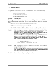
...the following error message is displayed on the screen, press any other error message is displayed, perform Check 2. *** Bad RTC battery *** Check system. Satellite A100/A105 / TECRA A7 Maintenance Manual 2-9 2.4 System Board 2 Troubleshooting 2.4 System Board To check if the system board is defective or...1 Message Check Procedure 2 Test Program Check Procedure 3 Replacement Check Procedure 1 Message Check When the power is lost because the battery has been exhausted or the system board is turned on , the system performs the self-diagnostic Power On Self Test (POST)...
...the following error message is displayed on the screen, press any other error message is displayed, perform Check 2. *** Bad RTC battery *** Check system. Satellite A100/A105 / TECRA A7 Maintenance Manual 2-9 2.4 System Board 2 Troubleshooting 2.4 System Board To check if the system board is defective or...1 Message Check Procedure 2 Test Program Check Procedure 3 Replacement Check Procedure 1 Message Check When the power is lost because the battery has been exhausted or the system board is turned on , the system performs the self-diagnostic Power On Self Test (POST)...
Maintenance Manual
Page 98
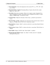
... in the above screen when 'Wait On Error' is enabled; ? LOG File Name : Display the file name of the test log, e.g. Remaining Battery Capacity: Remaining Battery Capacity detected in the above screen; ? Start Test Time (S.TIME): Display the test start time for the current test item or the test script... sequence. 3 Diagnostic Programs 3.2 Quick Start ? Manual Interrupt Method: Display 'Esc: Break' to tell the user how to manually interrupt the test process. 22 Satellite A100/A105 / TECRA A7 Maintenance Manual There is enabled; ? Break On Erro r: Display 'HALT' as in the current...
... in the above screen when 'Wait On Error' is enabled; ? LOG File Name : Display the file name of the test log, e.g. Remaining Battery Capacity: Remaining Battery Capacity detected in the above screen; ? Start Test Time (S.TIME): Display the test start time for the current test item or the test script... sequence. 3 Diagnostic Programs 3.2 Quick Start ? Manual Interrupt Method: Display 'Esc: Break' to tell the user how to manually interrupt the test process. 22 Satellite A100/A105 / TECRA A7 Maintenance Manual There is enabled; ? Break On Erro r: Display 'HALT' as in the current...

Maintenance Manual
Page 101
... the same option in random sequence. ? Interactive If the item is disabled, those test items will report FAIL. Monitor Battery Life Monitor the remaining battery capacity (percent). 3.3 Option 3 Diagnostic Programs ? Wait On Error Wait for the user to response with the test items that test item. ? Satellite A100/A105 / TECRA A7 Maintenance Manual 25
... the same option in random sequence. ? Interactive If the item is disabled, those test items will report FAIL. Monitor Battery Life Monitor the remaining battery capacity (percent). 3.3 Option 3 Diagnostic Programs ? Wait On Error Wait for the user to response with the test items that test item. ? Satellite A100/A105 / TECRA A7 Maintenance Manual 25

Maintenance Manual
Page 137
... Test Check whether the keyboard clock line works normally. Caps Lock LED, Num Lock LED and Scroll Lock LED. (2). HDD LED. 3. Satellite A100/A105 / TECRA A7 Maintenance Manual 61 Power LED , Battery LED , etc. (3). Keyboard Data Line Test Check whether the keyboard data line works normally. 2. 3.10 Peripheral 3 Diagnostic Programs 3.10 Peripheral Subtest...
... Test Check whether the keyboard clock line works normally. Caps Lock LED, Num Lock LED and Scroll Lock LED. (2). HDD LED. 3. Satellite A100/A105 / TECRA A7 Maintenance Manual 61 Power LED , Battery LED , etc. (3). Keyboard Data Line Test Check whether the keyboard data line works normally. 2. 3.10 Peripheral 3 Diagnostic Programs 3.10 Peripheral Subtest...

Maintenance Manual
Page 148
... Assembly Procedures 4-5 Tools and Equipment 4-6 Screw Tightening Torque 4-6 Colors of Screw Shanks 4-7 Symbols of Screws on the Computer Body 4-7 Symbol examples 4-7 Removing the Battery Pack 4-8 Installing the Battery Pack 4-9 Removing the PCI Expresss Card 4-10 Installing the PCI Expresss Card 4-11 Removing the Optional PC Card 4-12 Installing the Optional PC Card...MDC Card 4-21 4.2 HDD ...4-22 Removing the HDD 4-22 Installing the HDD 4-24 4.3 Speaker Cover and Keyboard 4-24 Removing the Speaker Cover and Keyboard 4-25 Satellite A100/A105 / TECRA A7 Maintenance Manual 4-iii
... Assembly Procedures 4-5 Tools and Equipment 4-6 Screw Tightening Torque 4-6 Colors of Screw Shanks 4-7 Symbols of Screws on the Computer Body 4-7 Symbol examples 4-7 Removing the Battery Pack 4-8 Installing the Battery Pack 4-9 Removing the PCI Expresss Card 4-10 Installing the PCI Expresss Card 4-11 Removing the Optional PC Card 4-12 Installing the Optional PC Card...MDC Card 4-21 4.2 HDD ...4-22 Removing the HDD 4-22 Installing the HDD 4-24 4.3 Speaker Cover and Keyboard 4-24 Removing the Speaker Cover and Keyboard 4-25 Satellite A100/A105 / TECRA A7 Maintenance Manual 4-iii


