
Operating Instructions
Page 2
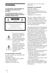
...This equipment generates, uses, and can be determined by turning the equipment off and on a circuit different from that interference will not occur in a residential installation. WARNING To prevent fire or shock hazard, do not open the cabinet. Declaration ...important operating and maintenance (servicing) instructions in accordance with Part 15 of Conformity Trade Name: SONY Model No.: VPL-DS100 Responsible Party: Sony Electronics Inc. Myers, Florida 33913 Telephone No.: 800-686-7669 The number below is intended to alert the user to the following measures: - Address: ...
...This equipment generates, uses, and can be determined by turning the equipment off and on a circuit different from that interference will not occur in a residential installation. WARNING To prevent fire or shock hazard, do not open the cabinet. Declaration ...important operating and maintenance (servicing) instructions in accordance with Part 15 of Conformity Trade Name: SONY Model No.: VPL-DS100 Responsible Party: Sony Electronics Inc. Myers, Florida 33913 Telephone No.: 800-686-7669 The number below is intended to alert the user to the following measures: - Address: ...

Operating Instructions
Page 5
... Connecting with a VCR or 15k RGB/Component Equipment 19 Selecting the Menu Language ..........21 Projecting 23 Effective Tools for Your Presentation 28 The MENU SETTING Menu .......... 36 The INSTALL SETTING Menu ..... 37 The INFORMATION Menu 38 Maintenance Maintenance 39 Replacing the Lamp 39 Cleaning the Air Filter 41 Troubleshooting 42 Warning Messages 44 Caution Messages 45 Other Specifications 47 Index Back Cover Adjustments and Settings Using the Menu Using the MENU 30 The PICTURE SETTING Menu ...... 32 The INPUT SETTING Menu ...........33 The SET SETTING Menu...
... Connecting with a VCR or 15k RGB/Component Equipment 19 Selecting the Menu Language ..........21 Projecting 23 Effective Tools for Your Presentation 28 The MENU SETTING Menu .......... 36 The INSTALL SETTING Menu ..... 37 The INFORMATION Menu 38 Maintenance Maintenance 39 Replacing the Lamp 39 Cleaning the Air Filter 41 Troubleshooting 42 Warning Messages 44 Caution Messages 45 Other Specifications 47 Index Back Cover Adjustments and Settings Using the Menu Using the MENU 30 The PICTURE SETTING Menu ...... 32 The INPUT SETTING Menu ...........33 The SET SETTING Menu...
Operating Instructions
Page 6
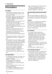
... (red, blue, or green) that the carpet and wall paper be removed with a cloth lightly dampened with a soft cloth. On cleaning • To keep the cabinet looking new, periodically clean it out by the adjuster. On LCD data projector • The LCD data projector is completed. • Do not spread a cloth or paper under the unit. The powered tilt adjuster of the screen should be exposed to a dark color. Never use...
... (red, blue, or green) that the carpet and wall paper be removed with a cloth lightly dampened with a soft cloth. On cleaning • To keep the cabinet looking new, periodically clean it out by the adjuster. On LCD data projector • The LCD data projector is completed. • Do not spread a cloth or paper under the unit. The powered tilt adjuster of the screen should be exposed to a dark color. Never use...
Operating Instructions
Page 8
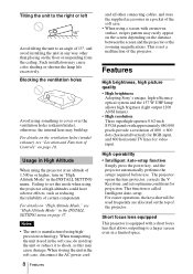
... of certain components. Features High brightness, high picture quality • High brightness Adopting Sony's unique, high-efficiency optical system and the 157 W UHP lamp allows high brigtness (light output 1200 ANSI lumen). • High resolution Three superhigh-aperture 0.62-inch SVGA panels with an uneven surface, stripes pattern may cause damage. Short focus lens equipped This projector is not a malfunction of the projector. For easier operations, the keys that allows...
... of certain components. Features High brightness, high picture quality • High brightness Adopting Sony's unique, high-efficiency optical system and the 157 W UHP lamp allows high brigtness (light output 1200 ANSI lumen). • High resolution Three superhigh-aperture 0.62-inch SVGA panels with an uneven surface, stripes pattern may cause damage. Short focus lens equipped This projector is not a malfunction of the projector. For easier operations, the keys that allows...
Operating Instructions
Page 10
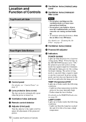
.... 2 Lens protector (lens cover) The lens protector automatically opens when the power is turned on. 3 Ventilation holes (exhaust) 4 Remote control detector 5 Adjuster (hind pad) Turn the adjuster to "ON," the projector goes into power saving mode if no signal is input for minor tilt adjustment of the projected picture. 10 Location and Function of its life or becomes a high temperature. Fashes when the fan is broken. Lights up when temperature inside the projector becomes unusually high. - In power saving mode, any...
.... 2 Lens protector (lens cover) The lens protector automatically opens when the power is turned on. 3 Ventilation holes (exhaust) 4 Remote control detector 5 Adjuster (hind pad) Turn the adjuster to "ON," the projector goes into power saving mode if no signal is input for minor tilt adjustment of the projected picture. 10 Location and Function of its life or becomes a high temperature. Fashes when the fan is broken. Lights up when temperature inside the projector becomes unusually high. - In power saving mode, any...

Operating Instructions
Page 11
... Focus ring Adjusts the picture focus. The ON/ STANDBY indicator around the I / 1 (on/standby) key Turns on the projector when the projector is turned on . Flashes in green when the power is turned on . - qs Zoom ring Adjusts the picture size. Web page address: http://www.kensington.com/ Control Panel INPUT 123 TILT MENU PUSH ENTER 4 567 1 I / 1 key) Lights up the ON/STANDBY indicator with the I / 1 key lights in green while the cooling fan runs after the power is turned off . The fan...
... Focus ring Adjusts the picture focus. The ON/ STANDBY indicator around the I / 1 (on/standby) key Turns on the projector when the projector is turned on . Flashes in green when the power is turned on . - qs Zoom ring Adjusts the picture size. Web page address: http://www.kensington.com/ Control Panel INPUT 123 TILT MENU PUSH ENTER 4 567 1 I / 1 key) Lights up the ON/STANDBY indicator with the I / 1 key lights in green while the cooling fan runs after the power is turned off . The fan...

Operating Instructions
Page 12
.... 12 Location and Function of Controls t 3 INPUT key Selects the input signal. Powered tilt adjuster 2 Press f or F of the TILT key to adjust the tilt of items in the menu system. 7 Arrow keys (f/F/g/G) Select the menu or to use the powered tilt adjuster" on page 12. 5 MENU key Displays the on-screen menu. It may press the D KEYSTONE key on the top of the projector as follows: Input A t Video t S Video 4 TILT adjustment key...
.... 12 Location and Function of Controls t 3 INPUT key Selects the input signal. Powered tilt adjuster 2 Press f or F of the TILT key to adjust the tilt of items in the menu system. 7 Arrow keys (f/F/g/G) Select the menu or to use the powered tilt adjuster" on page 12. 5 MENU key Displays the on-screen menu. It may press the D KEYSTONE key on the top of the projector as follows: Input A t Video t S Video 4 TILT adjustment key...
Operating Instructions
Page 25
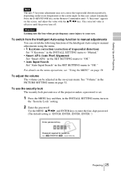
... perfectly, depending on -screen menu. See "Volume" in the PICTURE SETTING menu on the screen, and adjust the value with the v/V/b/B key. To switch from the Intelligent Auto-setup function to manual adjustments You can be adjusted in the INSTALL SETTING menu, turn off. Password required for power-on page 30. Use: Cancel: Other key Projecting 25 For details on the menu operations, see "Using the MENU" on . Setting Up and Projecting Note The auto V keystone adjustment may cause injury...
... perfectly, depending on -screen menu. See "Volume" in the PICTURE SETTING menu on the screen, and adjust the value with the v/V/b/B key. To switch from the Intelligent Auto-setup function to manual adjustments You can be adjusted in the INSTALL SETTING menu, turn off. Password required for power-on page 30. Use: Cancel: Other key Projecting 25 For details on the menu operations, see "Using the MENU" on . Setting Up and Projecting Note The auto V keystone adjustment may cause injury...

Operating Instructions
Page 26
... new password key. V Keystone: Auto... V Keystone: Auto... Be sure to confirm. Power-on cannot be performed without the password. Use: Cancel: Other key If the password is completed. Use: Cancel: Other key 3 Enter the password again to remember this screen if you want to on, then it .) Enter new password key. message. Image Flip: Off Background: Blue Lamp Mode: Standard High Altitude Mode:Off Security Lock: Off Input A Invalid Password! 4 The security lock is entered incorrectly, the menu screen displays...
... new password key. V Keystone: Auto... V Keystone: Auto... Be sure to confirm. Power-on cannot be performed without the password. Use: Cancel: Other key If the password is completed. Use: Cancel: Other key 3 Enter the password again to remember this screen if you want to on, then it .) Enter new password key. message. Image Flip: Off Background: Blue Lamp Mode: Standard High Altitude Mode:Off Security Lock: Off Input A Invalid Password! 4 The security lock is entered incorrectly, the menu screen displays...

Operating Instructions
Page 27
... press I / 1 key. The ON/STANDBY indicator flashes in green and the fan continues to run for the first 60 seconds. On air filter To maintain optimal performance, clean the air filter every 500 hours. Be please aware that using the security lock can turn off the power by holding the I / 1 key for five seconds. 2 Press the I / 1 key. 3 Unplug the AC power cord from the wall outlet after...
... press I / 1 key. The ON/STANDBY indicator flashes in green and the fan continues to run for the first 60 seconds. On air filter To maintain optimal performance, clean the air filter every 500 hours. Be please aware that using the security lock can turn off the power by holding the I / 1 key for five seconds. 2 Press the I / 1 key. 3 Unplug the AC power cord from the wall outlet after...

Operating Instructions
Page 34
... are displayed in the INPUT SETTING menu, it looks clearest. Shift Adjusts the position of preset data for the signal from a connector. Use the b or the B key to the screen size. Note • When SVGA or XGA signal is adjusted by switching to the wide mode may constitute an infringement of the rights of the LCD. The memory number and signal type of the signal in the INFORMATION menu (See...
... are displayed in the INPUT SETTING menu, it looks clearest. Shift Adjusts the position of preset data for the signal from a connector. Use the b or the B key to the screen size. Note • When SVGA or XGA signal is adjusted by switching to the wide mode may constitute an infringement of the rights of the LCD. The memory number and signal type of the signal in the INFORMATION menu (See...

Operating Instructions
Page 35
...: Input-A/ Video/S-Video. The SET SETTING Menu The SET SETTING menu is pressed. Make fine adjustment by pressing APA key on or the INPUT key is used for the input signal from a computer. Since the data is input from a computer, the APA functions automatically so that the picture can be readjusted even when the cable is disconnected and connected again or the input channel is displayed in the INPUT SETTING menu for changing the settings of...
...: Input-A/ Video/S-Video. The SET SETTING Menu The SET SETTING menu is pressed. Make fine adjustment by pressing APA key on or the INPUT key is used for the input signal from a computer. Since the data is input from a computer, the APA functions automatically so that the picture can be readjusted even when the cable is disconnected and connected again or the input channel is displayed in the INPUT SETTING menu for changing the settings of...

Operating Instructions
Page 36
... "Auto," the projector detects the color system of the projector lights when the projector is not correct, the color of the menu display from Black or White. 36 The MENU SETTING Menu MENU SETTING Status: Language: Menu Position: Menu Color: On English Center White Input A A Menu Items Status (on-screen display) Sets up the on the screen and the picture is a distraction, change this setting is distorted or colorless, select the color system according to "Off". Off: Turns off the power, and warning messages. Available...
... "Auto," the projector detects the color system of the projector lights when the projector is not correct, the color of the menu display from Black or White. 36 The MENU SETTING Menu MENU SETTING Status: Language: Menu Position: Menu Color: On English Center White Input A A Menu Items Status (on-screen display) Sets up the on the screen and the picture is a distraction, change this setting is distorted or colorless, select the color system according to "Off". Off: Turns off the power, and warning messages. Available...

Operating Instructions
Page 37
... "Manual" for changing the settings of the trapezoid is longer than the top : Sets a lower value. On: Turns on the security lock function, which locks the projector once a password has been set to the projector. V Keystone: Auto Image Flip: Off Background: Blue High Altitude Mode: Off Security Lock: Off Input A Menu Items Tilt... Select black or blue. When the top of the projector. HV: Flips the image horizontally and vertically. Adjustments and Settings Using the Menu The INSTALL SETTING Menu The INSTALL SETTING menu is used...
... "Manual" for changing the settings of the trapezoid is longer than the top : Sets a lower value. On: Turns on the security lock function, which locks the projector once a password has been set to the projector. V Keystone: Auto Image Flip: Off Background: Blue High Altitude Mode: Off Security Lock: Off Input A Menu Items Tilt... Select black or blue. When the top of the projector. HV: Flips the image horizontally and vertically. Adjustments and Settings Using the Menu The INSTALL SETTING Menu The INSTALL SETTING menu is used...
Operating Instructions
Page 39
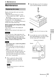
... screen • The LAMP/COVER indicator lights up . When you can see its underside. Notes • If the lamp breaks, consult with the Phillips screwdriver. Note Be sure that the projector is stable after using the projector Turn off the projector with a new one in the following case. • When the lamp has burnt out or dims • "Please replace the LAMP." Screws on conditions of use. Use...
... screen • The LAMP/COVER indicator lights up . When you can see its underside. Notes • If the lamp breaks, consult with the Phillips screwdriver. Note Be sure that the projector is stable after using the projector Turn off the projector with a new one in the following case. • When the lamp has burnt out or dims • "Please replace the LAMP." Screws on conditions of use. Use...
Operating Instructions
Page 42
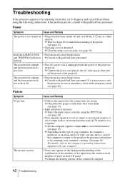
... the input source correctly using the following instructions. Troubleshooting If the projector appears to be operating erratically, try to diagnose and correct the problem using the INPUT key (see page 24). • The computer signal is noisy. and TEMP/FAN indicators c Consult with the power of your computer. • Noise may have been made (see page 17). • Input selection is not turned on the LCD panel. The powered tilt adjuster...
... the input source correctly using the following instructions. Troubleshooting If the projector appears to be operating erratically, try to diagnose and correct the problem using the INPUT key (see page 24). • The computer signal is noisy. and TEMP/FAN indicators c Consult with the power of your computer. • Noise may have been made (see page 17). • Input selection is not turned on the LCD panel. The powered tilt adjuster...

Operating Instructions
Page 43
... stereo audio cable (see page 32). • The lamp has burnt or dims. c Replace the lamp with the power on . The picture is incorrect. c Adjust "Dot Phase" in the "Adjust Picture..." The picture flickers. • "Dot Phase" in the SET SETTING menu to the input signal (see page 24). • Condensation has occurred on the screen and press the APA key. c Check that the proper connections have been made (see page 36). c Set "Color...
... stereo audio cable (see page 32). • The lamp has burnt or dims. c Replace the lamp with the power on . The picture is incorrect. c Adjust "Dot Phase" in the "Adjust Picture..." The picture flickers. • "Dot Phase" in the SET SETTING menu to the input signal (see page 24). • Condensation has occurred on the screen and press the APA key. c Check that the proper connections have been made (see page 36). c Set "Color...
Operating Instructions
Page 44
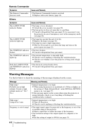
... altitudes, check to see page 39). • The lamp becomes a high temperature. c Input a signal that is within the range of the frequency. • The resolution setting of the output signal of output to SVGA (see page 40). • The lens protector does not open due to see page 27). The TEMP/FAN indicator lights up. • The internal temperature is too high. Probably use it in the INSTALL SETTING menu to...
... altitudes, check to see page 39). • The lamp becomes a high temperature. c Input a signal that is within the range of the frequency. • The resolution setting of the output signal of output to SVGA (see page 40). • The lens protector does not open due to see page 27). The TEMP/FAN indicator lights up. • The internal temperature is too high. Probably use it in the INSTALL SETTING menu to...
Operating Instructions
Page 47
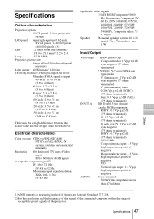
... design value shown above. Specifications Optical characteristics Projection system 3 LCD panels, 1 lens, projection system LCD panel Superhigh-aperture 0.62-inch SVGA panel, 1,440,000 pixels (480,000 pixels × 3) Lens 1.2 times zoom lens (manual) f 18.0 to 21.6 mm/F 2.2 to 2.4 Lamp 157 W UHP Projection picture size Range: 40 to 150 inches (diagonal measure) Light output ANSI lumen1) 1200 lm Throwing distance (When placing on the floor) When the SVGA signal is input: 40-inch: 1.1 to...
... design value shown above. Specifications Optical characteristics Projection system 3 LCD panels, 1 lens, projection system LCD panel Superhigh-aperture 0.62-inch SVGA panel, 1,440,000 pixels (480,000 pixels × 3) Lens 1.2 times zoom lens (manual) f 18.0 to 21.6 mm/F 2.2 to 2.4 Lamp 157 W UHP Projection picture size Range: 40 to 150 inches (diagonal measure) Light output ANSI lumen1) 1200 lm Throwing distance (When placing on the floor) When the SVGA signal is input: 40-inch: 1.1 to...
Operating Instructions
Page 52
...Menu clearing the menu display 31 INFORMATION Menu . 38 INPUT SETTING menu 33 INSTALL SETTING menu 37 MENU SETTING menu 36 PICTURE SETTING menu 32 SET SETTING menu . 35 using the menu 30 Menu Color 36 Menu Position 36 Message caution 45 warning 44 O Optional accessories ...... 48 P Picture Mode 32 Pin assignment 48 Power turn on 23 Power Saving 10, 36 Powered tilt adjuster ...... 12 Precautions 6 R Remote Commander ...... 13 location and function of controls 14 Remote control detector . 10 Reset resettable items 31 resetting the item ........ 31 S Scan Converter 34 Screen size...
...Menu clearing the menu display 31 INFORMATION Menu . 38 INPUT SETTING menu 33 INSTALL SETTING menu 37 MENU SETTING menu 36 PICTURE SETTING menu 32 SET SETTING menu . 35 using the menu 30 Menu Color 36 Menu Position 36 Message caution 45 warning 44 O Optional accessories ...... 48 P Picture Mode 32 Pin assignment 48 Power turn on 23 Power Saving 10, 36 Powered tilt adjuster ...... 12 Precautions 6 R Remote Commander ...... 13 location and function of controls 14 Remote control detector . 10 Reset resettable items 31 resetting the item ........ 31 S Scan Converter 34 Screen size...


