Operating Instructions
Page 1
Refer to them whenever you call upon your Sony dealer regarding this product. Record the serial number in the space provided below. 2-662-260-11 (6) Multi Channel AV Receiver Operating Instructions Owner's Record The model and serial numbers are located on the rear of the unit. STR-DG600 ©2006 Sony Corporation Model No. Serial No.
Refer to them whenever you call upon your Sony dealer regarding this product. Record the serial number in the space provided below. 2-662-260-11 (6) Multi Channel AV Receiver Operating Instructions Owner's Record The model and serial numbers are located on the rear of the unit. STR-DG600 ©2006 Sony Corporation Model No. Serial No.

Operating Instructions
Page 2
... To reduce the risk of fire or electric shock, do not expose this equipment does cause harmful interference to radio or television reception, which the receiver is connected. - To prevent fire, do not place objects filled with liquids, such as chemical waste. Do not install the appliance in a ...confined space, such as practical. 2US Increase the separation between the equipment and receiver. - To prevent fire or shock hazard, do not cover the ventilation of the apparatus with general house waste; Reorient or relocate the...
... To reduce the risk of fire or electric shock, do not expose this equipment does cause harmful interference to radio or television reception, which the receiver is connected. - To prevent fire, do not place objects filled with liquids, such as chemical waste. Do not install the appliance in a ...confined space, such as practical. 2US Increase the separation between the equipment and receiver. - To prevent fire or shock hazard, do not cover the ventilation of the apparatus with general house waste; Reorient or relocate the...
Operating Instructions
Page 3
... Theater Systems, Inc. Check your model number by looking at the lower right corner of area code AA only". CENTER L + - + - This receiver incorporates Dolby* Digital and Pro Logic Surround and the DTS** Digital Surround System. * Manufactured under license from Dolby Laboratories. "Dolby", "Pro Logic", "... "Models of XM Satellite Radio Inc. About area codes The area code of the receiver you purchased is shown on the remote is clearly indicated in the text, for model STR-DG600. Any difference in this manual describe the controls on the remote. The XM name and...
... Theater Systems, Inc. Check your model number by looking at the lower right corner of area code AA only". CENTER L + - + - This receiver incorporates Dolby* Digital and Pro Logic Surround and the DTS** Digital Surround System. * Manufactured under license from Dolby Laboratories. "Dolby", "Pro Logic", "... "Models of XM Satellite Radio Inc. About area codes The area code of the receiver you purchased is shown on the remote is clearly indicated in the text, for model STR-DG600. Any difference in this manual describe the controls on the remote. The XM name and...
Operating Instructions
Page 4
...2: Connecting speakers 16 3a: Connecting the audio components.........17 3b: Connecting the video components ........22 4: Connecting the antennas 29 5: Preparing the receiver and the remote .....30 6: Selecting the speaker system 32 7: Calibrating the appropriate settings automatically (AUTO CALIBRATION 32 8: Adjusting the speaker levels... 71 Naming inputs 72 Changing the display 73 Using the Sleep Timer 73 Recording using the receiver 74 Using the Remote Programming the remote 75 Additional Information Glossary 78 Precautions 80 Troubleshooting 81 Specifications 84 Index 87 4US...
...2: Connecting speakers 16 3a: Connecting the audio components.........17 3b: Connecting the video components ........22 4: Connecting the antennas 29 5: Preparing the receiver and the remote .....30 6: Selecting the speaker system 32 7: Calibrating the appropriate settings automatically (AUTO CALIBRATION 32 8: Adjusting the speaker levels... 71 Naming inputs 72 Changing the display 73 Using the Sleep Timer 73 Recording using the receiver 74 Using the Remote Programming the remote 75 Additional Information Glossary 78 Precautions 80 Troubleshooting 81 Specifications 84 Index 87 4US...

Operating Instructions
Page 5
TUNING + VIDEO 3 IN/PORTABLE AV IN VIDEO L AUDIO R DIGITAL(OPT) MULTI CHANNEL DECODING DISPLAY INPUT MODE INPUT SELECTOR MASTER VOLUME MEMORY/ CATEGORY ENTER MODE CATEGORY 2CH A.F.D. Turn to turn the receiver on or off (page 30, 38, 39, 60, 85). MOVIE MUSIC MULTI CH IN DIRECT ws wa w; Function Press to scan a station (page 61, 62...
TUNING + VIDEO 3 IN/PORTABLE AV IN VIDEO L AUDIO R DIGITAL(OPT) MULTI CHANNEL DECODING DISPLAY INPUT MODE INPUT SELECTOR MASTER VOLUME MEMORY/ CATEGORY ENTER MODE CATEGORY 2CH A.F.D. Turn to turn the receiver on or off (page 30, 38, 39, 60, 85). MOVIE MUSIC MULTI CH IN DIRECT ws wa w; Function Press to scan a station (page 61, 62...

Operating Instructions
Page 6
...MULTI CHANNEL DECODING lamp Lights up when multi channel audio is decoded (page 39). M INPUT SELECTOR Turn to select the input source to select a category (page 67). Press to playback (page 37, 38, 39, 59, 61, 63, 71, 72, 74). T VIDEO 3 IN/ To connect a camcorder or PORTABLE AV video game (page 28, 37). G Remote sensor Receives... signals from the components connected to select the audio directly from remote commander. O A.F.D. H DISPLAY Press to select the category mode (page 67). L MULTI CH IN Press to the MULTI CH...
...MULTI CHANNEL DECODING lamp Lights up when multi channel audio is decoded (page 39). M INPUT SELECTOR Turn to select the input source to select a category (page 67). Press to playback (page 37, 38, 39, 59, 61, 63, 71, 72, 74). T VIDEO 3 IN/ To connect a camcorder or PORTABLE AV video game (page 28, 37). G Remote sensor Receives... signals from the components connected to select the audio directly from remote commander. O A.F.D. H DISPLAY Press to select the category mode (page 67). L MULTI CH IN Press to the MULTI CH...
Operating Instructions
Page 7
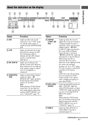
... decoding does not function for DTS format signals or for signals with a sampling frequency of more than 48 kHz. Lights up when the receiver applies Pro Logic processing to 2 channel signals in order to "ANALOG" (page 71). "; About the indicators on the display Getting Started 123 4 5 67 89 SW LFE SP...YES" (page 43) and the audio signal is activated (page 55). Name A SW B LFE C SP A/SP B D ;DIGITAL (EX) Function Lights up when the receiver is not set to "ANALOG" (page 71). Note When playing a DTS format disc, be sure that you have made digital connections and that INPUT MODE...
... decoding does not function for DTS format signals or for signals with a sampling frequency of more than 48 kHz. Lights up when the receiver applies Pro Logic processing to 2 channel signals in order to "ANALOG" (page 71). "; About the indicators on the display Getting Started 123 4 5 67 89 SW LFE SP...YES" (page 43) and the audio signal is activated (page 55). Name A SW B LFE C SP A/SP B D ;DIGITAL (EX) Function Lights up when the receiver is not set to "ANALOG" (page 71). Note When playing a DTS format disc, be sure that you have made digital connections and that INPUT MODE...
Operating Instructions
Page 8
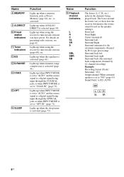
...to "COAX IN" (page 71). Name Q Playback channel indicators L R C SL SR S SBL SBR SB Function The letters (L, C, R, etc.) indicate the channels being input through the COAXIAL jack, or when INPUT MODE is set to show how the receiver downmixes the source sound (based on presetting radio stations,...Surround): 3/2.1 Output channel: When surround speaker is a digital signal being played back. AUTO SW LCR SL SR 8US Lights up when dynamic range compression is activated (page 41). Lights up when the sleep timer is activated (page 73). Lights up when using the receiver to tune in...
...to "COAX IN" (page 71). Name Q Playback channel indicators L R C SL SR S SBL SBR SB Function The letters (L, C, R, etc.) indicate the channels being input through the COAXIAL jack, or when INPUT MODE is set to show how the receiver downmixes the source sound (based on presetting radio stations,...Surround): 3/2.1 Output channel: When surround speaker is a digital signal being played back. AUTO SW LCR SL SR 8US Lights up when dynamic range compression is activated (page 41). Lights up when the sleep timer is activated (page 73). Lights up when using the receiver to tune in...
Operating Instructions
Page 10
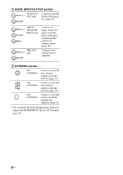
... 29). F ANTENNA section FM ANTENNA Connects to the AM loop antenna supplied with this receiver (page 29). White (L) Red (R) MULTI CHANNEL INPUT jack Black PRE OUT White (L) jack Red (R) Connects to an MD deck or CD player, etc. (page 21). E AUDIO INPUT/OUTPUT section ...AUDIO IN/ White (L) OUT jack Red (R) Connects to a Super Audio CD player or DVD player which has an analog audio jack for 5.1 channel sound (page...
... 29). F ANTENNA section FM ANTENNA Connects to the AM loop antenna supplied with this receiver (page 29). White (L) Red (R) MULTI CHANNEL INPUT jack Black PRE OUT White (L) jack Red (R) Connects to an MD deck or CD player, etc. (page 21). E AUDIO INPUT/OUTPUT section ...AUDIO IN/ White (L) OUT jack Red (R) Connects to a Super Audio CD player or DVD player which has an analog audio jack for 5.1 channel sound (page...
Operating Instructions
Page 11
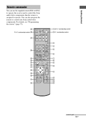
... Started Remote commander You can also program the remote to operate. ql qk qj qh TV ?/1 AV ?/1 ?/1 RM SET UP P SYSTEM STANDBY SLEEP VIDEO1 VIDEO2 VIDEO3 DVD MD/TAPE SA-CD/CD TUNER AUX MULTI CH 2CH A.F.D. MOVIE MUSIC 1 CATEGORY 2 3 DUAL CATEGORY MONO MODE 4 5 6 AUDIO ANGLE... JUMP/ PRESET/ TUNING TIME CH/D.SKIP 7 8 9 MEMORY SUBTITLE ENTER .> 0/10 >10/11 12 D.TUNING DISC ALT mM - You can use the supplied remote RM-AAP012 to operate the receiver and to control the Sony...
... Started Remote commander You can also program the remote to operate. ql qk qj qh TV ?/1 AV ?/1 ?/1 RM SET UP P SYSTEM STANDBY SLEEP VIDEO1 VIDEO2 VIDEO3 DVD MD/TAPE SA-CD/CD TUNER AUX MULTI CH 2CH A.F.D. MOVIE MUSIC 1 CATEGORY 2 3 DUAL CATEGORY MONO MODE 4 5 6 AUDIO ANGLE... JUMP/ PRESET/ TUNING TIME CH/D.SKIP 7 8 9 MEMORY SUBTITLE ENTER .> 0/10 >10/11 12 D.TUNING DISC ALT mM - You can use the supplied remote RM-AAP012 to operate the receiver and to control the Sony...

Operating Instructions
Page 12
... player, VCD player, LD player, DVD player, MD deck, DAT deck, tape deck, Blu-ray disc recorder, hard disc recorder, or PSX. Name A AV ?/1 B ?/1 SLEEP C MULTI CH D MUSIC E CATEGORY MODE F PRESET/ CH/D.SKIP +/- If you press the input buttons (wj). To turn off . Press to - select preset stations... tuner is programmed to adjust the volume level of the CD player or VCD player (multi-disc changer only). It changes the remote key function to select the channel entry mode, either one or two digit of the receiver. L AMP MENU M TV/VIDEO N AUTO CAL O WIDE P TV CH +a)/- R ...
... player, VCD player, LD player, DVD player, MD deck, DAT deck, tape deck, Blu-ray disc recorder, hard disc recorder, or PSX. Name A AV ?/1 B ?/1 SLEEP C MULTI CH D MUSIC E CATEGORY MODE F PRESET/ CH/D.SKIP +/- If you press the input buttons (wj). To turn off . Press to - select preset stations... tuner is programmed to adjust the volume level of the CD player or VCD player (multi-disc changer only). It changes the remote key function to select the channel entry mode, either one or two digit of the receiver. L AMP MENU M TV/VIDEO N AUTO CAL O WIDE P TV CH +a)/- R ...

Operating Instructions
Page 14
... or may operate differently than described. • The 12 button on the remote is intended to control Sony components as references when operating the receiver. Press MEMORY to control non-Sony components following the steps in tuner AUX Not assigned wk TV ?/1 Press to change the subtitles of a...program the remote to store a station. Therefore, depending on page 75. Name Function wj Input buttons Press one of the buttons to Multiplex, Bilingual or Multi channel TV sound of the satellite tuner, TV, or Blu-ray disc recorder. - a)The MASTER VOL +, TV VOL +, TV CH + and H buttons...
... or may operate differently than described. • The 12 button on the remote is intended to control Sony components as references when operating the receiver. Press MEMORY to control non-Sony components following the steps in tuner AUX Not assigned wk TV ?/1 Press to change the subtitles of a...program the remote to store a station. Therefore, depending on page 75. Name Function wj Input buttons Press one of the buttons to Multiplex, Bilingual or Multi channel TV sound of the satellite tuner, TV, or Blu-ray disc recorder. - a)The MASTER VOL +, TV VOL +, TV CH + and H buttons...

Operating Instructions
Page 15
... configuration You can place it wherever you want. 15US Enjoying a 5.1/7.1 channel system To fully enjoy theater-like multi channel surround sound requires five speakers (two front speakers, a center speaker, and two surround speakers) and a sub woofer (5.1 channel). Getting Started 1: Installing speakers This receiver allows you to use a 7.1 channel system (7 speakers and one additional surround back speaker...
... configuration You can place it wherever you want. 15US Enjoying a 5.1/7.1 channel system To fully enjoy theater-like multi channel surround sound requires five speakers (two front speakers, a center speaker, and two surround speakers) and a sub woofer (5.1 channel). Getting Started 1: Installing speakers This receiver allows you to use a 7.1 channel system (7 speakers and one additional surround back speaker...

Operating Instructions
Page 17
..., etc. 17US Before you begin, refer to "Component to be connected Component With Super Audio Digital audio outputa) CD player/CD player Multi-channel audio outputb) Page 18 20 Analog audio output 21 onlyc) MD deck/Tape Digital audio outputa) 18 deck Analog audio output 21 onlyc... proceed to "4: Connecting the antennas" (page 29). This connection is used to output audio decoded by the component's internal multi-channel decoder through this receiver. Getting Started 3a: Connecting the audio components How to hook up your components This section describes how to hook up all ...
..., etc. 17US Before you begin, refer to "Component to be connected Component With Super Audio Digital audio outputa) CD player/CD player Multi-channel audio outputb) Page 18 20 Analog audio output 21 onlyc) MD deck/Tape Digital audio outputa) 18 deck Analog audio output 21 onlyc... proceed to "4: Connecting the antennas" (page 29). This connection is used to output audio decoded by the component's internal multi-channel decoder through this receiver. Getting Started 3a: Connecting the audio components How to hook up your components This section describes how to hook up all ...
Operating Instructions
Page 19
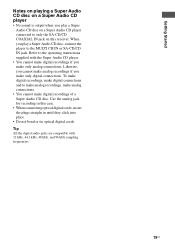
..., 48 kHz, and 96 kHz sampling frequencies. 19US Likewise, you cannot make only digital connections. To make digital recordings, make digital connections and to the MULTI CH IN or SA-CD/CD IN jack. Refer to only the SA-CD/CD COAXIAL IN jack on a Super Audio CD player • No... sound is output when you make digital recordings of a Super Audio CD disc. Use the analog jack for recording in this receiver. Getting Started Notes on playing a Super Audio CD disc on this case. • When connecting optical digital cords, insert the plugs straight in until they...
..., 48 kHz, and 96 kHz sampling frequencies. 19US Likewise, you cannot make only digital connections. To make digital recordings, make digital connections and to the MULTI CH IN or SA-CD/CD IN jack. Refer to only the SA-CD/CD COAXIAL IN jack on a Super Audio CD player • No... sound is output when you make digital recordings of a Super Audio CD disc. Use the analog jack for recording in this receiver. Getting Started Notes on playing a Super Audio CD disc on this case. • When connecting optical digital cords, insert the plugs straight in until they...

Operating Instructions
Page 20
... WOOFER SURROUND PRE OUT CENTER L + - + - Note When you make connections to the MULTI CH IN jacks, you can be used to adjust the level of this receiver to enjoy multi channel sound. Alternatively, the multi channel input jacks can connect it to the MULTI CH IN jacks of the speakers and sub woofer using the controls on...
... WOOFER SURROUND PRE OUT CENTER L + - + - Note When you make connections to the MULTI CH IN jacks, you can be used to adjust the level of this receiver to enjoy multi channel sound. Alternatively, the multi channel input jacks can connect it to the MULTI CH IN jacks of the speakers and sub woofer using the controls on...

Operating Instructions
Page 22
..." (page 29). 3b: Connecting the video components How to hook up your components This section describes how to hook up all your components to this receiver. Select the connection according to be connected The image quality depends on your components. 22US Before you begin, refer to "Component to be connected Component...
..." (page 29). 3b: Connecting the video components How to hook up your components This section describes how to hook up all your components to this receiver. Select the connection according to be connected The image quality depends on your components. 22US Before you begin, refer to "Component to be connected Component...
Operating Instructions
Page 23
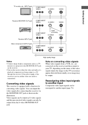
...the video signal output, the image on , neither video nor audio is equipped with a function for converting video signals. Converting video signals This receiver is transmitted. Reassigning video input signals to another input Component video input signals can only be output from a VCR, etc., are being output to... your TV, depending on the status of the receiver is not on the TV screen may appear distorted horizontally or no image may be reassigned to another input (page 71). 23US Getting Started...
...the video signal output, the image on , neither video nor audio is equipped with a function for converting video signals. Converting video signals This receiver is transmitted. Reassigning video input signals to another input Component video input signals can only be output from a VCR, etc., are being output to... your TV, depending on the status of the receiver is not on the TV screen may appear distorted horizontally or no image may be reassigned to another input (page 71). 23US Getting Started...
Operating Instructions
Page 24
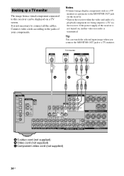
...) B Video cord (not supplied) C Component video cord (not supplied) 24US If the power supply of the receiver is not turned on, neither video nor audio is not necessary to a TV via the receiver. Connect video cords according to a TV monitor. TV monitor A B C DIGITAL OPTICAL VIDEO 1 IN VIDEO 2...OUT AUDIO IN DVD VIDEO 2 VIDEO 1 S-VIDEO OUT L L CENTER R SUB FRONT SURROUND WOOFER MULTI CH IN R SUB WOOFER SURROUND PRE OUT CENTER L + - + - Tip You can be displayed on the receiver when the video and audio of a playback component are being output to connect all the cables. ...
...) B Video cord (not supplied) C Component video cord (not supplied) 24US If the power supply of the receiver is not turned on, neither video nor audio is not necessary to a TV via the receiver. Connect video cords according to a TV monitor. TV monitor A B C DIGITAL OPTICAL VIDEO 1 IN VIDEO 2...OUT AUDIO IN DVD VIDEO 2 VIDEO 1 S-VIDEO OUT L L CENTER R SUB FRONT SURROUND WOOFER MULTI CH IN R SUB WOOFER SURROUND PRE OUT CENTER L + - + - Tip You can be displayed on the receiver when the video and audio of a playback component are being output to connect all the cables. ...

Operating Instructions
Page 26
... S-VIDEO IN IN L S-VIDEO S-VIDEO OUT IN L R R AUDIO IN AUDIO IN AUDIO OUT AUDIO IN DVD VIDEO 2 VIDEO 1 S-VIDEO OUT L L CENTER R SUB FRONT SURROUND WOOFER MULTI CH IN R SUB WOOFER SURROUND PRE OUT CENTER L + - + - For details, see "Naming inputs" (page 72). 26US SPEAKERS L R SURROUND BACK L + - + - For details, see "Programming the remote... (not supplied) C Component video cord (not supplied) If you can use the button to change the factory setting of the VIDEO 1 input button on the receiver's display.
... S-VIDEO IN IN L S-VIDEO S-VIDEO OUT IN L R R AUDIO IN AUDIO IN AUDIO OUT AUDIO IN DVD VIDEO 2 VIDEO 1 S-VIDEO OUT L L CENTER R SUB FRONT SURROUND WOOFER MULTI CH IN R SUB WOOFER SURROUND PRE OUT CENTER L + - + - For details, see "Naming inputs" (page 72). 26US SPEAKERS L R SURROUND BACK L + - + - For details, see "Programming the remote... (not supplied) C Component video cord (not supplied) If you can use the button to change the factory setting of the VIDEO 1 input button on the receiver's display.


