Operating Instructions
Page 1
Serial No. Record the serial number in the space provided below. Refer to them whenever you call upon your Sony dealer regarding this product. 2-662-260-11 (6) Multi Channel AV Receiver Operating Instructions Owner's Record The model and serial numbers are located on the rear of the unit. Model No. STR-DG600 ©2006 Sony Corporation
Serial No. Record the serial number in the space provided below. Refer to them whenever you call upon your Sony dealer regarding this product. 2-662-260-11 (6) Multi Channel AV Receiver Operating Instructions Owner's Record The model and serial numbers are located on the rear of the unit. Model No. STR-DG600 ©2006 Sony Corporation

Operating Instructions
Page 2
...cable ground shall be determined by turning the equipment off and on the apparatus. CAUTION You are designed to persons. Reorient or relocate the receiving antenna. - To prevent fire, do not cover the ventilation of the apparatus with liquids, such as vases, on the apparatus. If ... on , the user is encouraged to try to radio or television reception, which the receiver is intended to alert the user to operate this equipment. Increase the separation between the equipment and receiver. - Note to CATV system installer: This reminder is no guarantee that to which can...
...cable ground shall be determined by turning the equipment off and on the apparatus. CAUTION You are designed to persons. Reorient or relocate the receiving antenna. - To prevent fire, do not cover the ventilation of the apparatus with liquids, such as vases, on the apparatus. If ... on , the user is encouraged to try to radio or television reception, which the receiver is intended to alert the user to operate this equipment. Increase the separation between the equipment and receiver. - Note to CATV system installer: This reminder is no guarantee that to which can...
Operating Instructions
Page 3
...in this manual are for receiver operation. 3US CENTER L + - + - "Dolby", "Pro Logic", "Surround EX", and the double-D symbol are trademarks of Dolby Laboratories. ** "DTS", "DTS-ES", "Neo:6", and "DTS 96/24" are trademarks of area code U is not available for model STR-DG600. R SURROUND BACK SPEAKERS...of XM Satellite Radio Inc. R FRONT B AC OUTLET Area code Any differences in operation is shown on the remote. This receiver incorporates Dolby* Digital and Pro Logic Surround and the DTS** Digital Surround System. * Manufactured under license from Dolby Laboratories. R...
...in this manual are for receiver operation. 3US CENTER L + - + - "Dolby", "Pro Logic", "Surround EX", and the double-D symbol are trademarks of Dolby Laboratories. ** "DTS", "DTS-ES", "Neo:6", and "DTS 96/24" are trademarks of area code U is not available for model STR-DG600. R SURROUND BACK SPEAKERS...of XM Satellite Radio Inc. R FRONT B AC OUTLET Area code Any differences in operation is shown on the remote. This receiver incorporates Dolby* Digital and Pro Logic Surround and the DTS** Digital Surround System. * Manufactured under license from Dolby Laboratories. R...
Operating Instructions
Page 4
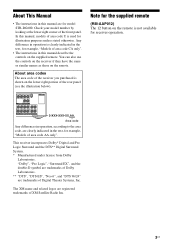
...2: Connecting speakers 16 3a: Connecting the audio components.........17 3b: Connecting the video components ........22 4: Connecting the antennas 29 5: Preparing the receiver and the remote .....30 6: Selecting the speaker system 32 7: Calibrating the appropriate settings automatically (AUTO CALIBRATION 32 8: Adjusting the speaker levels... 71 Naming inputs 72 Changing the display 73 Using the Sleep Timer 73 Recording using the receiver 74 Using the Remote Programming the remote 75 Additional Information Glossary 78 Precautions 80 Troubleshooting 81 Specifications 84 Index 87 4US...
...2: Connecting speakers 16 3a: Connecting the audio components.........17 3b: Connecting the video components ........22 4: Connecting the antennas 29 5: Preparing the receiver and the remote .....30 6: Selecting the speaker system 32 7: Calibrating the appropriate settings automatically (AUTO CALIBRATION 32 8: Adjusting the speaker levels... 71 Naming inputs 72 Changing the display 73 Using the Sleep Timer 73 Recording using the receiver 74 Using the Remote Programming the remote 75 Additional Information Glossary 78 Precautions 80 Troubleshooting 81 Specifications 84 Index 87 4US...

Operating Instructions
Page 5
... Press to scan a station (page 61, 62). continued 5US Turn to turn the receiver on or off (page 30, 38, 39, 60, 85). Name A ?/1 B SPEAKERS (OFF/A/B/A+B) C TUNING MODE D TUNING +/- TUNING + VIDEO 3 IN/PORTABLE AV IN VIDEO L AUDIO R DIGITAL(OPT) MULTI CHANNEL DECODING DISPLAY INPUT MODE INPUT SELECTOR MASTER VOLUME MEMORY/ CATEGORY ENTER MODE CATEGORY...
... Press to scan a station (page 61, 62). continued 5US Turn to turn the receiver on or off (page 30, 38, 39, 60, 85). Name A ?/1 B SPEAKERS (OFF/A/B/A+B) C TUNING MODE D TUNING +/- TUNING + VIDEO 3 IN/PORTABLE AV IN VIDEO L AUDIO R DIGITAL(OPT) MULTI CHANNEL DECODING DISPLAY INPUT MODE INPUT SELECTOR MASTER VOLUME MEMORY/ CATEGORY ENTER MODE CATEGORY...

Operating Instructions
Page 6
...listen to select 2CH STEREO mode (page 59, 60). P 2CH Press to high quality analog sound (page 59). G Remote sensor Receives signals from the components connected to store a station or enter the selection when selecting the settings (page 31). I INPUT MODE Press ... VIDEO 3 IN/ To connect a camcorder or PORTABLE AV video game (page 28, 37). M INPUT SELECTOR Turn to select the input source to adjust the volume level of selectable items appears here (page 7). F MULTI CHANNEL DECODING lamp Lights up when multi channel audio is decoded (page 39). J MASTER VOLUME Turn...
...listen to select 2CH STEREO mode (page 59, 60). P 2CH Press to high quality analog sound (page 59). G Remote sensor Receives signals from the components connected to store a station or enter the selection when selecting the settings (page 31). I INPUT MODE Press ... VIDEO 3 IN/ To connect a camcorder or PORTABLE AV video game (page 28, 37). M INPUT SELECTOR Turn to select the input source to adjust the volume level of selectable items appears here (page 7). F MULTI CHANNEL DECODING lamp Lights up when multi channel audio is decoded (page 39). J MASTER VOLUME Turn...
Operating Instructions
Page 7
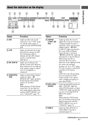
...) F DTS (-ES)/ (96/24) G NEO:6 Function Lights up when DTS-ES signals are input. "DTS-ES" lights up when the receiver applies Pro Logic processing to 2 channel signals in order to "ANALOG" (page 71). Lights up when the Pro Logic II Movie/Music/ Game decoder is activated (page 55). However...ANALOG" (page 71). "; Lights up when Dolby Digital signals are set to output the center and surround channel signals. Name A SW B LFE C SP A/SP B D ;DIGITAL (EX) Function Lights up when the receiver is not set to the speaker system used. Lights up according to "YES" (page 43) and the ...
...) F DTS (-ES)/ (96/24) G NEO:6 Function Lights up when DTS-ES signals are input. "DTS-ES" lights up when the receiver applies Pro Logic processing to 2 channel signals in order to "ANALOG" (page 71). Lights up when the Pro Logic II Movie/Music/ Game decoder is activated (page 55). However...ANALOG" (page 71). "; Lights up when Dolby Digital signals are set to output the center and surround channel signals. Name A SW B LFE C SP A/SP B D ;DIGITAL (EX) Function Lights up when the receiver is not set to the speaker system used. Lights up according to "YES" (page 43) and the ...
Operating Instructions
Page 8
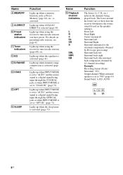
... Lights up when using the receiver to tune in radio stations you have preset. Lights up when the equalizer is set to "COAX IN" (page 71). Name Q Playback channel indicators L R C SL SR S SBL SBR SB Function The letters (L, C, R, etc.) indicate the channels being input through the COAXIAL jack..., or when INPUT MODE is selected (page 59). AUTO SW LCR SL SR 8US The boxes around the letters vary to show how the receiver downmixes the source sound (based on presetting radio stations,...
... Lights up when using the receiver to tune in radio stations you have preset. Lights up when the equalizer is set to "COAX IN" (page 71). Name Q Playback channel indicators L R C SL SR S SBL SBR SB Function The letters (L, C, R, etc.) indicate the channels being input through the COAXIAL jack..., or when INPUT MODE is selected (page 59). AUTO SW LCR SL SR 8US The boxes around the letters vary to show how the receiver downmixes the source sound (based on presetting radio stations,...
Operating Instructions
Page 10
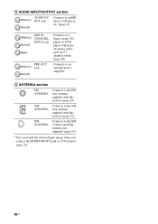
... Connects to the FM wire antenna supplied with this receiver (page 29). E AUDIO INPUT/OUTPUT section AUDIO IN/ White (L) OUT jack Red (R) Connects to a Super Audio CD player or DVD player which has an analog audio jack for 5.1 channel sound (page 20). White (L) Red (R) MULTI CHANNEL INPUT jack Black PRE OUT White (L) jack Red...
... Connects to the FM wire antenna supplied with this receiver (page 29). E AUDIO INPUT/OUTPUT section AUDIO IN/ White (L) OUT jack Red (R) Connects to a Super Audio CD player or DVD player which has an analog audio jack for 5.1 channel sound (page 20). White (L) Red (R) MULTI CHANNEL INPUT jack Black PRE OUT White (L) jack Red...
Operating Instructions
Page 11
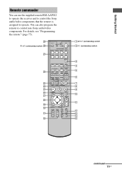
ql qk qj qh TV ?/1 AV ?/1 ?/1 RM SET UP P SYSTEM STANDBY SLEEP VIDEO1 VIDEO2 VIDEO3 DVD MD/TAPE SA-CD/CD TUNER AUX MULTI CH 2CH A.F.D. For details, see "Programming the remote" (page 75). MOVIE MUSIC 1 CATEGORY 2 3 DUAL CATEGORY MONO MODE 4 5 6 AUDIO ANGLE JUMP/ PRESET/ TUNING TIME CH/D.SKIP 7 ...TV/ AMP TV CH VIDEO MENU AUTO WIDE CAL 1 AV ?/1 (on/standby) switch 2 ?/1 (on /standby) switch wk wj wh wg wf wd ws wa w; You can use the supplied remote RM-AAP012 to operate the receiver and to control the Sony audio/video components that the remote is assigned to control ...
ql qk qj qh TV ?/1 AV ?/1 ?/1 RM SET UP P SYSTEM STANDBY SLEEP VIDEO1 VIDEO2 VIDEO3 DVD MD/TAPE SA-CD/CD TUNER AUX MULTI CH 2CH A.F.D. For details, see "Programming the remote" (page 75). MOVIE MUSIC 1 CATEGORY 2 3 DUAL CATEGORY MONO MODE 4 5 6 AUDIO ANGLE JUMP/ PRESET/ TUNING TIME CH/D.SKIP 7 ...TV/ AMP TV CH VIDEO MENU AUTO WIDE CAL 1 AV ?/1 (on/standby) switch 2 ?/1 (on /standby) switch wk wj wh wg wf wd ws wa w; You can use the supplied remote RM-AAP012 to operate the receiver and to control the Sony audio/video components that the remote is assigned to control ...

Operating Instructions
Page 12
.... Press to mute the sound. G ALT Function Press to stop playback of the CD player, VCD player, DVD player, MD deck, or LD player (multi-disc changer only). select preset stations. - skip disc of the VCR, CD player, VCD player, LD player, DVD player, MD deck, DAT deck,...to activate the Auto Calibration function. Press to select a disc directly of the receiver. Press to select preset TV channels. Press to select the input signal (TV input or video input). Note The function of all components, press ?/1 and AV ?/1 (A) at the same time, it will turn on or off. Press ALT...
.... Press to mute the sound. G ALT Function Press to stop playback of the CD player, VCD player, DVD player, MD deck, or LD player (multi-disc changer only). select preset stations. - skip disc of the VCR, CD player, VCD player, LD player, DVD player, MD deck, DAT deck,...to activate the Auto Calibration function. Press to select a disc directly of the receiver. Press to select preset TV channels. Press to select the input signal (TV input or video input). Note The function of all components, press ?/1 and AV ?/1 (A) at the same time, it will turn on or off. Press ALT...

Operating Instructions
Page 14
... disc recorder, or PSX. Press ALT (G) and then press SUBTITLE to Multiplex, Bilingual or Multi channel TV sound of the input buttons, the receiver turns on the remote is intended to control Sony components as an example only. Name Function wj Input buttons Press one of the buttons to select... above operation may not be possible or may not work depending on the model. • The above explanation is not available for receiver operation. 14US Button Assigned Sony component VIDEO1 VCR (VTR mode 3) VIDEO2 VCR (VTR mode 1) VIDEO3 VCR (VTR mode 2) DVD DVD player MD/TAPE MD deck...
... disc recorder, or PSX. Press ALT (G) and then press SUBTITLE to Multiplex, Bilingual or Multi channel TV sound of the input buttons, the receiver turns on the remote is intended to control Sony components as an example only. Name Function wj Input buttons Press one of the buttons to select... above operation may not be possible or may not work depending on the model. • The above explanation is not available for receiver operation. 14US Button Assigned Sony component VIDEO1 VCR (VTR mode 3) VIDEO2 VCR (VTR mode 1) VIDEO3 VCR (VTR mode 2) DVD DVD player MD/TAPE MD deck...

Operating Instructions
Page 15
... you want. 15US Getting Started 1: Installing speakers This receiver allows you to use a 7.1 channel system (7 speakers and one additional surround back speaker (6.1 channel) or two surround back speakers (7.1 channel) (see "Using the surround back decoding mode" on page 46). Enjoying a 5.1/7.1 channel system To fully enjoy theater-like multi channel surround sound requires five speakers (two front speakers...
... you want. 15US Getting Started 1: Installing speakers This receiver allows you to use a 7.1 channel system (7 speakers and one additional surround back speaker (6.1 channel) or two surround back speakers (7.1 channel) (see "Using the surround back decoding mode" on page 46). Enjoying a 5.1/7.1 channel system To fully enjoy theater-like multi channel surround sound requires five speakers (two front speakers...

Operating Instructions
Page 17
This connection is used to output audio decoded by the component's internal multi-channel decoder through this receiver. Getting Started 3a: Connecting the audio components How to hook up your components This section describes how to hook up all your components to this receiver. Component to be connected" below for the pages which describe how...
This connection is used to output audio decoded by the component's internal multi-channel decoder through this receiver. Getting Started 3a: Connecting the audio components How to hook up your components This section describes how to hook up all your components to this receiver. Component to be connected" below for the pages which describe how...
Operating Instructions
Page 19
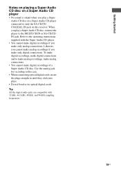
... COAXIAL IN jack on a Super Audio CD player • No sound is output when you play a Super Audio CD disc, connect the player to the MULTI CH IN or SA-CD/CD IN jack. Likewise, you cannot make analog recordings if you make only digital connections. Use the analog jack for... recording in this receiver. Tip All the digital audio jacks are compatible with the Super Audio CD player. • You cannot make digital recordings if you make only analog...
... COAXIAL IN jack on a Super Audio CD player • No sound is output when you play a Super Audio CD disc, connect the player to the MULTI CH IN or SA-CD/CD IN jack. Likewise, you cannot make analog recordings if you make only digital connections. Use the analog jack for... recording in this receiver. Tip All the digital audio jacks are compatible with the Super Audio CD player. • You cannot make digital recordings if you make only analog...

Operating Instructions
Page 20
... + - Note When you make connections to the MULTI CH IN jacks, you can be used to connect an external multi channel decoder. SPEAKERS L R SURROUND BACK L + - + - Alternatively, the multi channel input jacks can connect it to the MULTI CH IN jacks of the speakers and sub woofer using... A SPEAKERS A Audio cord (not supplied) B Monaural audio cord (not supplied) 20US Connecting components with multi channel output jacks If your DVD or Super Audio CD player is equipped with multi channel output jacks, you will need to adjust the level of this receiver to enjoy multi channel sound.
... + - Note When you make connections to the MULTI CH IN jacks, you can be used to connect an external multi channel decoder. SPEAKERS L R SURROUND BACK L + - + - Alternatively, the multi channel input jacks can connect it to the MULTI CH IN jacks of the speakers and sub woofer using... A SPEAKERS A Audio cord (not supplied) B Monaural audio cord (not supplied) 20US Connecting components with multi channel output jacks If your DVD or Super Audio CD player is equipped with multi channel output jacks, you will need to adjust the level of this receiver to enjoy multi channel sound.

Operating Instructions
Page 22
... according to "4: Connecting the antennas" (page 29). Before you begin, refer to "Component to be connected The image quality depends on your components to this receiver. After hooking up your components. 22US
... according to "4: Connecting the antennas" (page 29). Before you begin, refer to "Component to be connected The image quality depends on your components to this receiver. After hooking up your components. 22US
Operating Instructions
Page 23
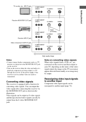
... signals from the S-video MONITOR OUT jack. Getting Started TV monitor etc., INPUT jack COMPONENT VIDEO S-VIDEO VIDEO Receiver MONITOR OUT jack COMPONENT VIDEO S-VIDEO VIDEO Receiver INPUT jack Video component OUTPUT jack COMPONENT VIDEO Signal processing S-VIDEO VIDEO COMPONENT VIDEO S-VIDEO VIDEO High quality image ... and this upconverted video signals can only be output from a VCR, etc., are being output to a TV through the receiver. Reassigning video input signals to another input Component video input signals can output the video signal after connecting this...
... signals from the S-video MONITOR OUT jack. Getting Started TV monitor etc., INPUT jack COMPONENT VIDEO S-VIDEO VIDEO Receiver MONITOR OUT jack COMPONENT VIDEO S-VIDEO VIDEO Receiver INPUT jack Video component OUTPUT jack COMPONENT VIDEO Signal processing S-VIDEO VIDEO COMPONENT VIDEO S-VIDEO VIDEO High quality image ... and this upconverted video signals can only be output from a VCR, etc., are being output to a TV through the receiver. Reassigning video input signals to another input Component video input signals can output the video signal after connecting this...
Operating Instructions
Page 24
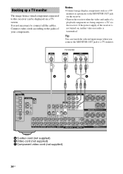
...S-VIDEO S-VIDEO OUT IN L R R AUDIO IN AUDIO IN AUDIO OUT AUDIO IN DVD VIDEO 2 VIDEO 1 S-VIDEO OUT L L CENTER R SUB FRONT SURROUND WOOFER MULTI CH IN R SUB WOOFER SURROUND PRE OUT CENTER L + - + - Notes • Connect image display components such as a TV monitor or a projector to the ...MONITOR OUT jack on the receiver. • Turn on , neither video nor audio is not necessary to connect all the cables. Hooking up a TV monitor The image from a visual ...
...S-VIDEO S-VIDEO OUT IN L R R AUDIO IN AUDIO IN AUDIO OUT AUDIO IN DVD VIDEO 2 VIDEO 1 S-VIDEO OUT L L CENTER R SUB FRONT SURROUND WOOFER MULTI CH IN R SUB WOOFER SURROUND PRE OUT CENTER L + - + - Notes • Connect image display components such as a TV monitor or a projector to the ...MONITOR OUT jack on the receiver. • Turn on , neither video nor audio is not necessary to connect all the cables. Hooking up a TV monitor The image from a visual ...

Operating Instructions
Page 26
... S-VIDEO IN IN L S-VIDEO S-VIDEO OUT IN L R R AUDIO IN AUDIO IN AUDIO OUT AUDIO IN DVD VIDEO 2 VIDEO 1 S-VIDEO OUT L L CENTER R SUB FRONT SURROUND WOOFER MULTI CH IN R SUB WOOFER SURROUND PRE OUT CENTER L + - + - For details, see "Programming the remote" (page 75). • You can also rename the VIDEO 1 input so... R R SURROUND FRONT A SPEAKERS B A DVD recorder A S-video cord (not supplied) B Video cord (not supplied) C Component video cord (not supplied) If you can be displayed on the receiver's display. SPEAKERS L R SURROUND BACK L + - + -
... S-VIDEO IN IN L S-VIDEO S-VIDEO OUT IN L R R AUDIO IN AUDIO IN AUDIO OUT AUDIO IN DVD VIDEO 2 VIDEO 1 S-VIDEO OUT L L CENTER R SUB FRONT SURROUND WOOFER MULTI CH IN R SUB WOOFER SURROUND PRE OUT CENTER L + - + - For details, see "Programming the remote" (page 75). • You can also rename the VIDEO 1 input so... R R SURROUND FRONT A SPEAKERS B A DVD recorder A S-video cord (not supplied) B Video cord (not supplied) C Component video cord (not supplied) If you can be displayed on the receiver's display. SPEAKERS L R SURROUND BACK L + - + -


