Operating Instructions
Page 4
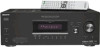
........49 Using only the front speakers (2CH STEREO 52 Listening to the sound without any adjustment (ANALOG DIRECT 52 Resetting sound fields to the initial settings 53 Tuner Operations Listening to FM/AM radio 53 Storing FM stations automatically (AUTOBETICAL...Connecting speakers 14 3a: Connecting the audio components.........15 3b: Connecting the video components ........18 4: Connecting the antennas 24 5: Preparing the receiver and the remote .....25 6: Selecting the speaker system 26 7: Calibrating the appropriate settings automatically (AUTO CALIBRATION 27 8: Adjusting the speaker...
........49 Using only the front speakers (2CH STEREO 52 Listening to the sound without any adjustment (ANALOG DIRECT 52 Resetting sound fields to the initial settings 53 Tuner Operations Listening to FM/AM radio 53 Storing FM stations automatically (AUTOBETICAL...Connecting speakers 14 3a: Connecting the audio components.........15 3b: Connecting the video components ........18 4: Connecting the antennas 24 5: Preparing the receiver and the remote .....25 6: Selecting the speaker system 26 7: Calibrating the appropriate settings automatically (AUTO CALIBRATION 27 8: Adjusting the speaker...
Operating Instructions
Page 25
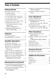
... "CLEARED" appears. "PUSH" and "ENTER" appears on the display for the first time, initialize the receiver by performing the following items are reset to their factory defaults. The following procedure. VOLTAGE SELECTOR 120V 220V 240V Connecting the AC power cord Connect ...MIC PHONES VIDEO 3 IN/PORTABLE AV IN VIDEO L AUDIO R MULTI CHANNEL DECODING DISPLAY INPUT MODE INPUT SELECTOR MASTER VOLUME MEMORY/ TUNING ENTER MODE TUNING 2CH A.F.D. SURROUND BACK L + - This procedure can be used to return settings you have made to turn off the receiver. 2 Hold down ?/1 for inputs...
... "CLEARED" appears. "PUSH" and "ENTER" appears on the display for the first time, initialize the receiver by performing the following items are reset to their factory defaults. The following procedure. VOLTAGE SELECTOR 120V 220V 240V Connecting the AC power cord Connect ...MIC PHONES VIDEO 3 IN/PORTABLE AV IN VIDEO L AUDIO R MULTI CHANNEL DECODING DISPLAY INPUT MODE INPUT SELECTOR MASTER VOLUME MEMORY/ TUNING ENTER MODE TUNING 2CH A.F.D. SURROUND BACK L + - This procedure can be used to return settings you have made to turn off the receiver. 2 Hold down ?/1 for inputs...
Operating Instructions
Page 53
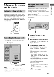
MOVIE MUSIC MULTI CH IN DIRECT 2 1 Press ?/1 to the receiver (page 24). For details on the display and all sound fields are reset to their initial setting. Area code U, CA CEL, CEK, AU, TW, KR, TH6, SP E2 AR FM 100 kHz 50 kHz 50 kHz... IN/PORTABLE AV IN VIDEO L AUDIO R MULTI CHANNEL DECODING DISPLAY INPUT MODE INPUT SELECTOR MASTER VOLUME MEMORY/ TUNING ENTER MODE TUNING 2CH A.F.D. Tuner Operations Listening to FM/AM radio You can be changed (page 73). "S.F. Resetting sound fields to the initial settings Be sure to use the buttons on the receiver for direct ...
MOVIE MUSIC MULTI CH IN DIRECT 2 1 Press ?/1 to the receiver (page 24). For details on the display and all sound fields are reset to their initial setting. Area code U, CA CEL, CEK, AU, TW, KR, TH6, SP E2 AR FM 100 kHz 50 kHz 50 kHz... IN/PORTABLE AV IN VIDEO L AUDIO R MULTI CHANNEL DECODING DISPLAY INPUT MODE INPUT SELECTOR MASTER VOLUME MEMORY/ TUNING ENTER MODE TUNING 2CH A.F.D. Tuner Operations Listening to FM/AM radio You can be changed (page 73). "S.F. Resetting sound fields to the initial settings Be sure to use the buttons on the receiver for direct ...
Operating Instructions
Page 65
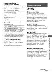
... transmitting video signal information consisting of front (left/right), center, surround (left and right surround channels so that the sound can be reproduced in stereo, more realistic sound with a DVD1 or DVD3.... To clear all remote button assignments Press ?/1, AUTO CAL and MASTER VOL - It is reset to the operating instructions supplied with a VTR 2 or VTR 3 setting which correspond to ... DVD3)b) CD player 5 MD deck 6 Tape deck B 7 Tuner (this receiver) 8 DVR (Digital CATV terminal) 9 DSS (Digital Satellite Receiver) 0/10 a)Sony VCRs are combined and transmitted together.
... transmitting video signal information consisting of front (left/right), center, surround (left and right surround channels so that the sound can be reproduced in stereo, more realistic sound with a DVD1 or DVD3.... To clear all remote button assignments Press ?/1, AUTO CAL and MASTER VOL - It is reset to the operating instructions supplied with a VTR 2 or VTR 3 setting which correspond to ... DVD3)b) CD player 5 MD deck 6 Tape deck B 7 Tuner (this receiver) 8 DVR (Digital CATV terminal) 9 DSS (Digital Satellite Receiver) 0/10 a)Sony VCRs are combined and transmitted together.
Operating Instructions
Page 71
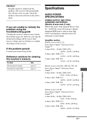
... Check the speaker connection and turn off after a few seconds. If the problem persist Consult your nearest Sony dealer. Reference sections for clearing the receiver's memory To clear All memorized settings Customized sound fields See page 25 page 53 Specifications AUDIO POWER SPECIFICATIONS POWER... channel minimum RMS power, with no more than 0.09% total harmonic distortion from 20 - 20,000 Hz; If you will automatically turn on the receiver. PROTECT Irregular current is output from the speakers. The receiver will have to readjust all memorized settings will be reset to...
... Check the speaker connection and turn off after a few seconds. If the problem persist Consult your nearest Sony dealer. Reference sections for clearing the receiver's memory To clear All memorized settings Customized sound fields See page 25 page 53 Specifications AUDIO POWER SPECIFICATIONS POWER... channel minimum RMS power, with no more than 0.09% total harmonic distortion from 20 - 20,000 Hz; If you will automatically turn on the receiver. PROTECT Irregular current is output from the speakers. The receiver will have to readjust all memorized settings will be reset to...
Operating Instructions
Page 73
... 50 dB µ/m (at 1,000 kHz or 999 kHz) 6)You can change the AM tuning scale to 10 kHz (or 9 kHz), repeat the procedure. To reset the scale to 9 kHz or 10 kHz. All preset stations will be erased when you are subject to change the tuning scale. AM tuner section... area code of the component you change without notice. Design and specifications are using, see page 3. After tuning in any AM station, turn off the receiver. While holding down TUNING MODE, press ?/1.
... 50 dB µ/m (at 1,000 kHz or 999 kHz) 6)You can change the AM tuning scale to 10 kHz (or 9 kHz), repeat the procedure. To reset the scale to 9 kHz or 10 kHz. All preset stations will be erased when you are subject to change the tuning scale. AM tuner section... area code of the component you change without notice. Design and specifications are using, see page 3. After tuning in any AM station, turn off the receiver. While holding down TUNING MODE, press ?/1.
Service Manual
Page 2
...70 kHz +0.5/-2 dB (with sound field and tone (DG500) or equalizer (DG600) bypassed) Inputs Analog Sensitivity: ...DG500), EQUALIZER (DG600) Gain levels ±6 dB, 1 dB step 4) INPUT SHORT (with sound field and tone (DG500... Area code DG500: US, AEP, UK, AUS, KR, E2 DG500: SP, MY, TH DG500: CND DG500: TW DG600... AM loop antenna (1) Remote commander RM-AAU005 (1) (DG500) Remote commander RM-AAP012 (1) (DG600: US, CND)...10 kHz (or 9 kHz), repeat the procedure. STR-DG500/DG600 Ver. 1.1 1) Measured under the following ... surround back. To reset the scale to change without notice. •...
...70 kHz +0.5/-2 dB (with sound field and tone (DG500) or equalizer (DG600) bypassed) Inputs Analog Sensitivity: ...DG500), EQUALIZER (DG600) Gain levels ±6 dB, 1 dB step 4) INPUT SHORT (with sound field and tone (DG500... Area code DG500: US, AEP, UK, AUS, KR, E2 DG500: SP, MY, TH DG500: CND DG500: TW DG600... AM loop antenna (1) Remote commander RM-AAU005 (1) (DG500) Remote commander RM-AAP012 (1) (DG600: US, CND)...10 kHz (or 9 kHz), repeat the procedure. STR-DG500/DG600 Ver. 1.1 1) Measured under the following ... surround back. To reset the scale to change without notice. •...

Service Manual
Page 14
... segments light on at the same time, then each segment lights on one after connecting the antenna. * Procedure: Check that can be received by the tuner, and sets up the broadcasts. appears for a moment. Be sure to start scanning after another. * Procedure: While depressing... m MHz [MULTI CHANNEL DECODING] LED light on the main power. Either the message "C.MODE.AV 1" or "C.MODE.AV 2" appears for a moment and the present contents are reset to turn off . 14 While depressing the [TUNING MODE] button, press the ?/1 button to turn on the main power. STR-DG500/DG600 SECTION 3...
... segments light on at the same time, then each segment lights on one after connecting the antenna. * Procedure: Check that can be received by the tuner, and sets up the broadcasts. appears for a moment. Be sure to start scanning after another. * Procedure: While depressing... m MHz [MULTI CHANNEL DECODING] LED light on the main power. Either the message "C.MODE.AV 1" or "C.MODE.AV 2" appears for a moment and the present contents are reset to turn off . 14 While depressing the [TUNING MODE] button, press the ?/1 button to turn on the main power. STR-DG500/DG600 SECTION 3...
Service Manual
Page 15
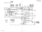
... AUDIO IN IN LRLR -3 -4 J403 -1 -2 VIDEO 3 IN/ PORTABLE AV IN AUDIO LR -2 -3 J298(2/2) DIR FUNCTION SELECT IC401 R-CH R-CH R-CH R-CH R-CH R-CH DG600:US,CND MODEL XM SECTION C (Page 18) XM L XM R XM REQ XM DBPOWER XM COMMAND XM DACMS XM RESET R-CH AEP,UK MODEL TN1 FM/AM TUNER UNIT... MULTI CH IN 46 22 28 32 30 34 SEL 36 SW 38 60 MCU 59 I/F L SEL SL SEL 10 13 12 17 R-CH 11 R-CH 14 R-CH R-CH C SEL SW SEL SBL SEL DIGITAL SECTION B (Page 16) SBL OUT SW OUT C OUT SL OUT L OUT 54 56 51 52 49 STR-DG500...
... AUDIO IN IN LRLR -3 -4 J403 -1 -2 VIDEO 3 IN/ PORTABLE AV IN AUDIO LR -2 -3 J298(2/2) DIR FUNCTION SELECT IC401 R-CH R-CH R-CH R-CH R-CH R-CH DG600:US,CND MODEL XM SECTION C (Page 18) XM L XM R XM REQ XM DBPOWER XM COMMAND XM DACMS XM RESET R-CH AEP,UK MODEL TN1 FM/AM TUNER UNIT... MULTI CH IN 46 22 28 32 30 34 SEL 36 SW 38 60 MCU 59 I/F L SEL SL SEL 10 13 12 17 R-CH 11 R-CH 14 R-CH R-CH C SEL SW SEL SBL SEL DIGITAL SECTION B (Page 16) SBL OUT SW OUT C OUT SL OUT L OUT 54 56 51 52 49 STR-DG500...
Service Manual
Page 19
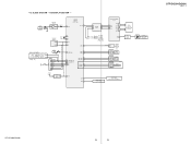
...I/ I XM SECTION G (Page 18) XM MIXMO XM MIXMI FLASH PROGRAMMING CNP504 1 FLASH1 2 FLASH2 7 MD2 6 MD0 RESET 5 SCL 8 SDA 9 +3.3V (STBY) IC1111 2 RESET 1 56 POWER KEY 28 FLASH1/XM_TX 27 FLASH2/XM_RX 51 MD2 49 MD0 77 RSTX SIRCS 54 ENC A 31 ENC B...SECTION (Page 15) SW1 1 SIRCS 1 OUT 1 3 REMOTE CONTROL RECEIVER IC102 RV101 INPUT SELECTOR 1 RV102 3 MASTER VOLUME DG600 1 RV103 3 TUNING +/- 4-5. LED DRIVER Q110 SW NETWORK S101-107,124 SW NETWORK S108-111,115,112 (DG600) D105 MULTI CHANNEL DECODING STR-DG500/DG600 Ver. 1.1 STR-DG500/DG600 19 19 BLOCK DIAGRAM -
...I/ I XM SECTION G (Page 18) XM MIXMO XM MIXMI FLASH PROGRAMMING CNP504 1 FLASH1 2 FLASH2 7 MD2 6 MD0 RESET 5 SCL 8 SDA 9 +3.3V (STBY) IC1111 2 RESET 1 56 POWER KEY 28 FLASH1/XM_TX 27 FLASH2/XM_RX 51 MD2 49 MD0 77 RSTX SIRCS 54 ENC A 31 ENC B...SECTION (Page 15) SW1 1 SIRCS 1 OUT 1 3 REMOTE CONTROL RECEIVER IC102 RV101 INPUT SELECTOR 1 RV102 3 MASTER VOLUME DG600 1 RV103 3 TUNING +/- 4-5. LED DRIVER Q110 SW NETWORK S101-107,124 SW NETWORK S108-111,115,112 (DG600) D105 MULTI CHANNEL DECODING STR-DG500/DG600 Ver. 1.1 STR-DG500/DG600 19 19 BLOCK DIAGRAM -

Service Manual
Page 50
...STR-DG500/DG600 IC1401 PCM1800E/2K (DIGITAL BOARD (3/5)) 24 23 22 21 20 19 18 17 16 15 14 13 DIGITAL MODULATOR DIGITAL MODULATOR 1/64 DECIMATION FILTER & LOW-CUT FILTER SERIAL I/O INTERFACE & MODE/FORMAT CONTROL SINGLE-END DEFERENTIAL CONVERTER 1 REFERENCE 234 SINGLE-END DEFERENTIAL CONVERTER 5 CLOCK/ TIMING CONTROL RESET... INTERFACE SERIAL INPUT INTERFACE 4X/8X OVER SAMPLING DIGITAL FILTER WITH FUNCTION CONTROLLER ZERO DETECT DAC LPF DAC LPF DAC LPF ENHANCED MULTI- SIGMA MODULE DAC LPF DAC LPF DAC LPF DAC LPF 123456 78 9 10 11 12 24 VCC3 23 AGND3 22 VCC4...
...STR-DG500/DG600 IC1401 PCM1800E/2K (DIGITAL BOARD (3/5)) 24 23 22 21 20 19 18 17 16 15 14 13 DIGITAL MODULATOR DIGITAL MODULATOR 1/64 DECIMATION FILTER & LOW-CUT FILTER SERIAL I/O INTERFACE & MODE/FORMAT CONTROL SINGLE-END DEFERENTIAL CONVERTER 1 REFERENCE 234 SINGLE-END DEFERENTIAL CONVERTER 5 CLOCK/ TIMING CONTROL RESET... INTERFACE SERIAL INPUT INTERFACE 4X/8X OVER SAMPLING DIGITAL FILTER WITH FUNCTION CONTROLLER ZERO DETECT DAC LPF DAC LPF DAC LPF ENHANCED MULTI- SIGMA MODULE DAC LPF DAC LPF DAC LPF DAC LPF 123456 78 9 10 11 12 24 VCC3 23 AGND3 22 VCC4...

Service Manual
Page 54
... CONTROL IC 35 HDOUT O Serial data output for 8CH DAC IC 21 VSS - Ground 2 XRST I Not used (Fixed at H) 50 PAGE2 O Not used (Open) 8 VSS - STR-DG500/DG600 • IC Pin Descriptions IC1501 CXD9718BQ (DSP) (DIGITAL BOARD (2/5)) Pin No. Pin Name I Power supply pin (+2.6 V) 11 VSS - Ground 49 WMD0...
... CONTROL IC 35 HDOUT O Serial data output for 8CH DAC IC 21 VSS - Ground 2 XRST I Not used (Fixed at H) 50 PAGE2 O Not used (Open) 8 VSS - STR-DG500/DG600 • IC Pin Descriptions IC1501 CXD9718BQ (DSP) (DIGITAL BOARD (2/5)) Pin No. Pin Name I Power supply pin (+2.6 V) 11 VSS - Ground 49 WMD0...

Service Manual
Page 56
... MB90488BPF-G-175E1 (SYSTEM CONTROL) (DIGITAL BOARD (5/5)) (STR-DG500) IC1101 MB90488BPF-G-178E1 (SYSTEM CONTROL) (DIGITAL BOARD (5/5)) (STR-DG600) Pin No. encoder (A) signal input (STR-DG600) 22 TUNING_B I Destination detection signal input 42 VSS - encoder (B) signal input (STR-DG600) 23 VCC5 - Ground 38 ADCC I ADCC ... 26 XM_RST O XM radio reset signal output (STR-DG600) 27 FLASH2/XM_RX I Flash programming signal input 2/XM radio RX signal input (STR-DG600) 28 FLASH1/XM_TX O Flash programming signal output 1/XM radio TX signal output (STR-DG600) 29 SDA I/O Serial...
... MB90488BPF-G-175E1 (SYSTEM CONTROL) (DIGITAL BOARD (5/5)) (STR-DG500) IC1101 MB90488BPF-G-178E1 (SYSTEM CONTROL) (DIGITAL BOARD (5/5)) (STR-DG600) Pin No. encoder (A) signal input (STR-DG600) 22 TUNING_B I Destination detection signal input 42 VSS - encoder (B) signal input (STR-DG600) 23 VCC5 - Ground 38 ADCC I ADCC ... 26 XM_RST O XM radio reset signal output (STR-DG600) 27 FLASH2/XM_RX I Flash programming signal input 2/XM radio RX signal input (STR-DG600) 28 FLASH1/XM_TX O Flash programming signal output 1/XM radio TX signal output (STR-DG600) 29 SDA I/O Serial...

Service Manual
Page 57
STR-DG500/DG600 Pin No. ANALOG_SW_DATA 85 O (DE8) 86 D595_DATA O 87 D595_CLK O 88 D595_OE O 89 D595_LAT...O 75 TUNED I 76 STEREO I 77 RSTX I /O EXPANDER IC Digital input select 2 signal output (STR-DG600) Digital input select 1 signal output (STR-DG600) 96/24 signal output for DSP IC Xmode signal output for DIR IC Clock select signal output for... signal output Tuner serial data input Tuner latch signal output Tuned signal detection input Stereo signal detection input Reset signal input Tuner mute signal output Not used (Open) Not used (Connect to VSS) Ground Clock signal...
STR-DG500/DG600 Pin No. ANALOG_SW_DATA 85 O (DE8) 86 D595_DATA O 87 D595_CLK O 88 D595_OE O 89 D595_LAT...O 75 TUNED I 76 STEREO I 77 RSTX I /O EXPANDER IC Digital input select 2 signal output (STR-DG600) Digital input select 1 signal output (STR-DG600) 96/24 signal output for DSP IC Xmode signal output for DIR IC Clock select signal output for... signal output Tuner serial data input Tuner latch signal output Tuned signal detection input Stereo signal detection input Reset signal input Tuner mute signal output Not used (Open) Not used (Connect to VSS) Ground Clock signal...


