
Limited Warranty (U.S. Only)
Page 1
...WARRANTY OF MERCHANTABILITY OR FITNESS FOR A PARTICULAR PURPOSE ON THIS PRODUCT IS LIMITED IN DURATION TO THE DURATION OF THIS WARRANTY. PARTS: In addition, Sony will repair or replace the Product, at no charge, or pay the labor charges to service the Product. This warranty is ... or removed from the Product. For your authorized dealer, call : Sony Customer Information Services Center 1-800-222-7669 or visit the Sony Web Site: www.sony.com For an accessory or part not available from your convenience, Sony Electronics Inc. After the warranty period, you must pay for one ...
...WARRANTY OF MERCHANTABILITY OR FITNESS FOR A PARTICULAR PURPOSE ON THIS PRODUCT IS LIMITED IN DURATION TO THE DURATION OF THIS WARRANTY. PARTS: In addition, Sony will repair or replace the Product, at no charge, or pay the labor charges to service the Product. This warranty is ... or removed from the Product. For your authorized dealer, call : Sony Customer Information Services Center 1-800-222-7669 or visit the Sony Web Site: www.sony.com For an accessory or part not available from your convenience, Sony Electronics Inc. After the warranty period, you must pay for one ...
Operating Instructions
Page 2
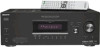
... will not occur in accordance with the limits for a Class B digital device, pursuant to the point of cable entry as close to Part 15 of the FCC Rules. WARNING This equipment has been tested and found to comply with the instructions, may be connected to the grounding...constitute a risk of electric shock to operate this equipment. If this equipment does cause harmful interference to radio or television reception, which the receiver is provided to call CATV system installer's attention to Article 820-40 of the building, as practical. 2GB Increase the separation between the ...
... will not occur in accordance with the limits for a Class B digital device, pursuant to the point of cable entry as close to Part 15 of the FCC Rules. WARNING This equipment has been tested and found to comply with the instructions, may be connected to the grounding...constitute a risk of electric shock to operate this equipment. If this equipment does cause harmful interference to radio or television reception, which the receiver is provided to call CATV system installer's attention to Article 820-40 of the building, as practical. 2GB Increase the separation between the ...
Operating Instructions
Page 4
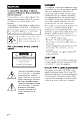
... (COMPONENT VIDEO ASSIGN) ....... 61 Naming inputs 62 Changing the display 62 Using the Sleep Timer 63 Recording using the receiver 63 Using the Remote Changing button assignments 64 Additional Information Glossary 65 Precautions 67 Troubleshooting 68 Specifications 71 Index 74 4GB ... 55 (Models of area code CEL, CEK only) Presetting radio stations 56 Using the Radio Data System (RDS).......... 59 (Models of parts 5 1: Installing speakers 13 2: Connecting speakers 14 3a: Connecting the audio components.........15 3b: Connecting the video components ........18 4: Connecting the...
... (COMPONENT VIDEO ASSIGN) ....... 61 Naming inputs 62 Changing the display 62 Using the Sleep Timer 63 Recording using the receiver 63 Using the Remote Changing button assignments 64 Additional Information Glossary 65 Precautions 67 Troubleshooting 68 Specifications 71 Index 74 4GB ... 55 (Models of area code CEL, CEK only) Presetting radio stations 56 Using the Radio Data System (RDS).......... 59 (Models of parts 5 1: Installing speakers 13 2: Connecting speakers 14 3a: Connecting the audio components.........15 3b: Connecting the video components ........18 4: Connecting the...

Operating Instructions
Page 5
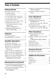
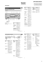
... Display The current status of the selected component or a list of parts Front panel 12 34 5 67 8 ?/1 SPEAKERS (OFF/A/B /A+B) AUTO CAL MIC PHONES VIDEO 3 IN/PORTABLE AV IN VIDEO L AUDIO R MULTI CHANNEL DECODING DISPLAY INPUT MODE INPUT SELECTOR MASTER VOLUME MEMORY/ TUNING ENTER MODE... TUNING 2CH A.F.D. ql qk qj qh qg qf qd qs qa q; 9 PUSH To remove the cover Press PUSH. continued 5GB B SPEAKERS (OFF/A/B/A+B) Press to turn the receiver...
... Display The current status of the selected component or a list of parts Front panel 12 34 5 67 8 ?/1 SPEAKERS (OFF/A/B /A+B) AUTO CAL MIC PHONES VIDEO 3 IN/PORTABLE AV IN VIDEO L AUDIO R MULTI CHANNEL DECODING DISPLAY INPUT MODE INPUT SELECTOR MASTER VOLUME MEMORY/ TUNING ENTER MODE... TUNING 2CH A.F.D. ql qk qj qh qg qf qd qs qa q; 9 PUSH To remove the cover Press PUSH. continued 5GB B SPEAKERS (OFF/A/B/A+B) Press to turn the receiver...
Operating Instructions
Page 73
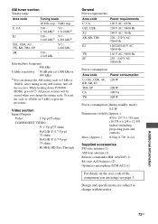
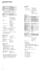
...standby mode) 0.2 W Dimensions (w/h/d) (Approx.) 430 × 157.5 × 316 mm (16 7/8 × 6 2/8 × 12 4/8 inches) including projecting parts and controls Mass (Approx.) 8.0 kg (17 lb 11 oz) Supplied accessories FM wire antenna (1) AM loop antenna (1) Remote commander RM-AAU005 (1) R6 (size-AA)...change the tuning scale. While holding down TUNING MODE, press ?/1. Additional Information 73GB After tuning in any AM station, turn off the receiver. Design and specifications are using, see page 3. AM tuner section Tuning range Area code Tuning scale 10 kHz step 9 kHz step ...
...standby mode) 0.2 W Dimensions (w/h/d) (Approx.) 430 × 157.5 × 316 mm (16 7/8 × 6 2/8 × 12 4/8 inches) including projecting parts and controls Mass (Approx.) 8.0 kg (17 lb 11 oz) Supplied accessories FM wire antenna (1) AM loop antenna (1) Remote commander RM-AAU005 (1) R6 (size-AA)...change the tuning scale. While holding down TUNING MODE, press ?/1. Additional Information 73GB After tuning in any AM station, turn off the receiver. Design and specifications are using, see page 3. AM tuner section Tuning range Area code Tuning scale 10 kHz step 9 kHz step ...
Service Manual
Page 2
... × 12 4/8 inches) including projecting parts and controls Mass (Approx.) 8.0 kg (17 lb 11 oz) Supplied accessories FM wire antenna (1) AM loop antenna (1) Remote commander RM-AAU005 (1) (DG500) Remote commander RM-AAP012 (1) (DG600: ... model E2 : 120 V AC area in any AM station, turn off the receiver. All preset stations will be no sound output. 3) Measured under the following conditions...SHORT (with sound field and tone (DG500) or equalizer (DG600) bypassed). 5) Weighted network, input level. To reset the scale to 9 kHz or 10 kHz. STR-DG500/DG600 Ver. 1.1 1) Measured under ...
... × 12 4/8 inches) including projecting parts and controls Mass (Approx.) 8.0 kg (17 lb 11 oz) Supplied accessories FM wire antenna (1) AM loop antenna (1) Remote commander RM-AAU005 (1) (DG500) Remote commander RM-AAP012 (1) (DG600: ... model E2 : 120 V AC area in any AM station, turn off the receiver. All preset stations will be no sound output. 3) Measured under the following conditions...SHORT (with sound field and tone (DG500) or equalizer (DG600) bypassed). 5) Weighted network, input level. To reset the scale to 9 kHz or 10 kHz. STR-DG500/DG600 Ver. 1.1 1) Measured under ...
Service Manual
Page 3
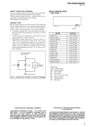
.... A. REPLACE THESE COMPONENTS WITH SONY PARTS WHOSE PART NUMBERS APPEAR AS SHOWN IN THIS MANUAL OR IN SUPPLEMENTS PUBLISHED BY SONY. LES COMPOSANTS IDENTIFIÉS PAR UNE MARQUE 0 SUR LES DIAGRAMMES SCHÉMATIQUES ET LA LISTE DES PIÈCES SONT CRITIQUES POUR LA SÉCURITÉ DE FONCTIONNEMENT. STR-DG500/DG600 Ver. 1.1 SAFETY CHECK...
.... A. REPLACE THESE COMPONENTS WITH SONY PARTS WHOSE PART NUMBERS APPEAR AS SHOWN IN THIS MANUAL OR IN SUPPLEMENTS PUBLISHED BY SONY. LES COMPOSANTS IDENTIFIÉS PAR UNE MARQUE 0 SUR LES DIAGRAMMES SCHÉMATIQUES ET LA LISTE DES PIÈCES SONT CRITIQUES POUR LA SÉCURITÉ DE FONCTIONNEMENT. STR-DG500/DG600 Ver. 1.1 SAFETY CHECK...

Service Manual
Page 4
... S-video Up Convert Section (DG600 39 4-28. Printed Wiring Boards - Schematic Diagram - GENERAL Description and location of parts (STR-DG500 5 Description and location of parts (STR-DG600: US, CND model 7 2. Back Panel Section 11 2-4. Block Diagram - Block Diagram - Schematic Diagram - Video... model 40 4-30. DISASSEMBLY 2-1. Center/Surround Back Speaker Section 33 4-20. Video Section 37 4-25. Printed Wiring Board - STR-DG500/DG600 Ver. 1.1 TABLE OF CONTENTS 1. Key/Display Section 19 4-6. Main Section (3/3 25 4-12. Digital Section (4/5 31 4-...
... S-video Up Convert Section (DG600 39 4-28. Printed Wiring Boards - Schematic Diagram - GENERAL Description and location of parts (STR-DG500 5 Description and location of parts (STR-DG600: US, CND model 7 2. Back Panel Section 11 2-4. Block Diagram - Block Diagram - Schematic Diagram - Video... model 40 4-30. DISASSEMBLY 2-1. Center/Surround Back Speaker Section 33 4-20. Video Section 37 4-25. Printed Wiring Board - STR-DG500/DG600 Ver. 1.1 TABLE OF CONTENTS 1. Key/Display Section 19 4-6. Main Section (3/3 25 4-12. Digital Section (4/5 31 4-...
Service Manual
Page 5
...OFF, A, B, A+B of parts Front panel 12 34 5 67 8 ?/1 SPEAKERS (OFF/A/B /A+B) AUTO CAL MIC PHONES VIDEO 3 IN/PORTABLE AV IN VIDEO L AUDIO R MULTI CHANNEL DECODING DISPLAY INPUT MODE INPUT ... when dynamic range compression is activated. Lights up when using the receiver to tune in radio stations you have made digital connections and that... components obtained by 6.1 channel decoding) Example: Recording format (Front/ Surround): 3/2.1 Output channel: When surround speaker is extracted from instruction manual. "; STR-DG500: SECTION 1 GENERAL STR-DG500/DG600 This section is ...
...OFF, A, B, A+B of parts Front panel 12 34 5 67 8 ?/1 SPEAKERS (OFF/A/B /A+B) AUTO CAL MIC PHONES VIDEO 3 IN/PORTABLE AV IN VIDEO L AUDIO R MULTI CHANNEL DECODING DISPLAY INPUT MODE INPUT ... when dynamic range compression is activated. Lights up when using the receiver to tune in radio stations you have made digital connections and that... components obtained by 6.1 channel decoding) Example: Recording format (Front/ Surround): 3/2.1 Output channel: When surround speaker is extracted from instruction manual. "; STR-DG500: SECTION 1 GENERAL STR-DG500/DG600 This section is ...
Service Manual
Page 7
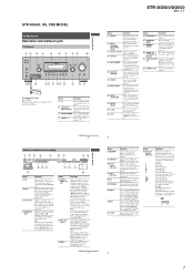
...such as Preset Memory (page 62), etc., is activated. G Remote sensor Receives signals from the SUB WOOFER jack. S MEMORY/ ENTER Press to select A.F.D....D TUNING +/- continued 7US Getting Started Getting Started STR-DG500/DG600 Ver. 1.1 Name Function E Display The current status of the selected component or a list of parts Front panel 12 3 4 5 67 89 q;...VIDEO 3 IN/PORTABLE AV IN VIDEO L AUDIO R DIGITAL(OPT) MULTI CHANNEL DECODING DISPLAY INPUT MODE INPUT SELECTOR MASTER VOLUME MEMORY/ CATEGORY ENTER MODE CATEGORY 2CH A.F.D. F MULTI CHANNEL DECODING lamp Lights up...
...such as Preset Memory (page 62), etc., is activated. G Remote sensor Receives signals from the SUB WOOFER jack. S MEMORY/ ENTER Press to select A.F.D....D TUNING +/- continued 7US Getting Started Getting Started STR-DG500/DG600 Ver. 1.1 Name Function E Display The current status of the selected component or a list of parts Front panel 12 3 4 5 67 89 q;...VIDEO 3 IN/PORTABLE AV IN VIDEO L AUDIO R DIGITAL(OPT) MULTI CHANNEL DECODING DISPLAY INPUT MODE INPUT SELECTOR MASTER VOLUME MEMORY/ CATEGORY ENTER MODE CATEGORY 2CH A.F.D. F MULTI CHANNEL DECODING lamp Lights up...

Service Manual
Page 21
...AC SELECT board (E2 model) SPEAKER C/SB board S VIDEO UP CONVERT board (DG600) XM board (DG600: US, CND model) STR-DG500/DG600 Ver. 1.1 THIS NOTE IS COMMON FOR PRINTED WIRING BOARDS AND SCHEMATIC DIAGRAMS. (In addition to normal production tolerances. • ...Parts on the parts face side seen from the (Side B) pattern face are taken with a VOM (Input impedance 10 MΩ). 4-7. Line. • Voltage and waveforms are dc with respect to waveforms. • Signal path. TH : Thai model. SP : Singapore model. E2 : 120 V AC area in E model. for safety. STR-DG500...
...AC SELECT board (E2 model) SPEAKER C/SB board S VIDEO UP CONVERT board (DG600) XM board (DG600: US, CND model) STR-DG500/DG600 Ver. 1.1 THIS NOTE IS COMMON FOR PRINTED WIRING BOARDS AND SCHEMATIC DIAGRAMS. (In addition to normal production tolerances. • ...Parts on the parts face side seen from the (Side B) pattern face are taken with a VOM (Input impedance 10 MΩ). 4-7. Line. • Voltage and waveforms are dc with respect to waveforms. • Signal path. TH : Thai model. SP : Singapore model. E2 : 120 V AC area in E model. for safety. STR-DG500...

Service Manual
Page 58
... mark 0 are critical for routine service. Les composants identifiés par une marque 0 sont critiques pour la sécurité. No. 2 #1 Part No. STR-DG500/DG600 Ver. 1.1 NOTE: • The mechanical parts with no reference number in the exploded views are not supplied. • Items marked "*" are not stocked since they may have some...
... mark 0 are critical for routine service. Les composants identifiés par une marque 0 sont critiques pour la sécurité. No. 2 #1 Part No. STR-DG500/DG600 Ver. 1.1 NOTE: • The mechanical parts with no reference number in the exploded views are not supplied. • Items marked "*" are not stocked since they may have some...

Service Manual
Page 59
...No. 51 51 51 51 51 51 51 51 51 52 Part No. Description Remark X-2103-321-1 FRONT PANEL ASSY (BLACK)...(BLACK) (DG500:US) X-2103-324-1 FRONT PANEL ASSY (BLACK)...(BLACK) (DG500:CND,AUS) X-2103-325-1 FRONT PANEL ASSY (SILVER)...(SILVER) (DG500:CND,E2,AUS,KR,MY,SP,TH,TW) X-2103-326... (BLACK)...(BLACK) (DG600:MY,SP) X-2103-653-1 FRONT PANEL ASSY (SILVER)...(SILVER) (DG600:CND) 4-977-358-01 CUSHION Ref. 5-2. FRONT PANEL SECTION STR-DG500/DG600 Ver. 1.1 not supplied (ADCC board) 56 not supplied (POWER board) not supplied (HEADPHONE board) 56 57 56 56 FL101 56 not supplied (VIDEO3 board...
...No. 51 51 51 51 51 51 51 51 51 52 Part No. Description Remark X-2103-321-1 FRONT PANEL ASSY (BLACK)...(BLACK) (DG500:US) X-2103-324-1 FRONT PANEL ASSY (BLACK)...(BLACK) (DG500:CND,AUS) X-2103-325-1 FRONT PANEL ASSY (SILVER)...(SILVER) (DG500:CND,E2,AUS,KR,MY,SP,TH,TW) X-2103-326... (BLACK)...(BLACK) (DG600:MY,SP) X-2103-653-1 FRONT PANEL ASSY (SILVER)...(SILVER) (DG600:CND) 4-977-358-01 CUSHION Ref. 5-2. FRONT PANEL SECTION STR-DG500/DG600 Ver. 1.1 not supplied (ADCC board) 56 not supplied (POWER board) not supplied (HEADPHONE board) 56 57 56 56 FL101 56 not supplied (VIDEO3 board...

Service Manual
Page 60
... (E2) CORD, POWER (AEP,UK,MY,SP,TH) CORD, POWER (US,CND) Ref. STR-DG500/DG600 Ver. 1.1 5-3. No. 0 106 0 106 107 0 F40 TN1 TN1 TN1 TN1 #1 Part No. No. 101 101 102 103 104 * 105 0 106 0 106 0 106 0 106 Part No. Description Remark 1-827-295-22 1-827-597-41 1-828-937-11 1-533-689...-12 1-693-675-11 CORD, POWER (AUS) CORD, POWER (TW) WIRE (FLAT TYPE) (5 CORE) (DG600:US,CND) FUSE, GLASS CYLINDRICAL (DIA. 5) (1A/125V) (DG600:US,CND) TUNER PACK (ANTENNA) (DG500:US,CND,E2) 1-693...
... (E2) CORD, POWER (AEP,UK,MY,SP,TH) CORD, POWER (US,CND) Ref. STR-DG500/DG600 Ver. 1.1 5-3. No. 0 106 0 106 107 0 F40 TN1 TN1 TN1 TN1 #1 Part No. No. 101 101 102 103 104 * 105 0 106 0 106 0 106 0 106 Part No. Description Remark 1-827-295-22 1-827-597-41 1-828-937-11 1-533-689...-12 1-693-675-11 CORD, POWER (AUS) CORD, POWER (TW) WIRE (FLAT TYPE) (5 CORE) (DG600:US,CND) FUSE, GLASS CYLINDRICAL (DIA. 5) (1A/125V) (DG600:US,CND) TUNER PACK (ANTENNA) (DG500:US,CND,E2) 1-693...

Service Manual
Page 61
STR-DG500/DG600 Ver. 1.1 5-4. CHASSIS SECTION not supplied (STANDBY board) not supplied (SB AMP board) (DG600) #1 152 #1...supplied 153 159 155 156 151 152 154 Ref. No. 0 F901 0 F901 0 F902 0 F902 Q503 Q504 Q533 Q534 Q603 Q604 #1 Part No. Description Remark 1-532-504-33 1-533-454-12 1-532-464-33 1-533-453-12 6-702-390-01 FUSE (T4A/250V) (...MN2488-OPY-MK MP1620-OPY-MK MN2488-OPY-MK MP1620-OPY-MK MN2488-OPY-MK 154 A-1158-598-A DIGITAL BOARD, COMPLETE (DG500:KR) Q754 6-702-391-01 TRANSISTOR MP1620-OPY-MK 154 A-1158-599-A DIGITAL BOARD, COMPLETE Q2572 8-729-026-08 TRANSISTOR...
STR-DG500/DG600 Ver. 1.1 5-4. CHASSIS SECTION not supplied (STANDBY board) not supplied (SB AMP board) (DG600) #1 152 #1...supplied 153 159 155 156 151 152 154 Ref. No. 0 F901 0 F901 0 F902 0 F902 Q503 Q504 Q533 Q534 Q603 Q604 #1 Part No. Description Remark 1-532-504-33 1-533-454-12 1-532-464-33 1-533-453-12 6-702-390-01 FUSE (T4A/250V) (...MN2488-OPY-MK MP1620-OPY-MK MN2488-OPY-MK MP1620-OPY-MK MN2488-OPY-MK 154 A-1158-598-A DIGITAL BOARD, COMPLETE (DG500:KR) Q754 6-702-391-01 TRANSISTOR MP1620-OPY-MK 154 A-1158-599-A DIGITAL BOARD, COMPLETE Q2572 8-729-026-08 TRANSISTOR...

Service Manual
Page 62
.... METAL:Metal-film resistor. uPC.. : µPC.. Replace only with mark 0 are seldom required for routine service. STR-DG500/DG600 Ver. 1.1 AC SELECT ADCC DIGITAL SECTION 6 ELECTRICAL PARTS LIST NOTE: • Due to standardization, replacements in the parts list may be anticipated when ordering these items. • SEMICONDUCTORS In each case, u : µ, for example...
.... METAL:Metal-film resistor. uPC.. : µPC.. Replace only with mark 0 are seldom required for routine service. STR-DG500/DG600 Ver. 1.1 AC SELECT ADCC DIGITAL SECTION 6 ELECTRICAL PARTS LIST NOTE: • Due to standardization, replacements in the parts list may be anticipated when ordering these items. • SEMICONDUCTORS In each case, u : µ, for example...

Service Manual
Page 64
...6-702-771-01 6-806-144-01 6-806-146-01 IC TA7805S IC BA50BC0T IC TA78033LS (AEP,UK) IC MB90488BPF-G-175E1 (DG500) IC MB90488BPF-G-178E1 (DG600) IC1103 IC1111 IC1131 IC1301 IC1301 8-759-242-70 6-702-913-01 6-705-866-01 6-805-...692-01 8-759-825-15 IC TC7WU04F (DG600) IC S-80929CNMC-G8ZT2G IC BR24L16FJ-WE2 IC LC890561W (DG600) IC LC89056W-E (DG500) IC1302 IC1303 IC1351 IC1352 IC1353 8-759-595-15 8-759-242-70 6-600-466-01 6-600-466-01 6-600-461-01 IC ...CNS504 1-568-828-11 CONNECTOR, FFC 9P CNS505 1-784-784-11 CONNECTOR, FFC 23P Ref. No. Part No. STR-DG500/DG600 Ver. 1.1 DIGITAL Ref...
...6-702-771-01 6-806-144-01 6-806-146-01 IC TA7805S IC BA50BC0T IC TA78033LS (AEP,UK) IC MB90488BPF-G-175E1 (DG500) IC MB90488BPF-G-178E1 (DG600) IC1103 IC1111 IC1131 IC1301 IC1301 8-759-242-70 6-702-913-01 6-705-866-01 6-805-...692-01 8-759-825-15 IC TC7WU04F (DG600) IC S-80929CNMC-G8ZT2G IC BR24L16FJ-WE2 IC LC890561W (DG600) IC LC89056W-E (DG500) IC1302 IC1303 IC1351 IC1352 IC1353 8-759-595-15 8-759-242-70 6-600-466-01 6-600-466-01 6-600-461-01 IC ...CNS504 1-568-828-11 CONNECTOR, FFC 9P CNS505 1-784-784-11 CONNECTOR, FFC 23P Ref. No. Part No. STR-DG500/DG600 Ver. 1.1 DIGITAL Ref...

Service Manual
Page 68
...220PF 220PF 0.1uF 0.1uF 0.1uF < CONNECTOR > CNS100 1-784-784-11 CONNECTOR, FFC 23P < DIODE > Remark Ref. Part No. C138 C139 C140 C141 C142 Part No. STR-DG500/DG600 Ver. 1.1 DISPLAY HEADPHONE Ref. Description Remark 10% 50V 10% 50V 10% 50V 10% 50V 10% 50V 10%...-21 SWITCH, TACTILE (A.F.D.) SWITCH, TACTILE (2CH) SWITCH, TACTILE (MEMORY/ENTER) SWITCH, TACTILE (TUNING -) (DG500) SWITCH, TACTILE (CATEGORY -) (DG600:US,CND) D105 6-500-647-01 LED SEL5E20C-STP15 (MULTI CHANNEL DECODING) < VACUUM FLUORESCENT DISPLAY > FL101 1-519-866-01 VACUUM FLUORESCENT DISPLAY < IC > S109 S110 S110 ...
...220PF 220PF 0.1uF 0.1uF 0.1uF < CONNECTOR > CNS100 1-784-784-11 CONNECTOR, FFC 23P < DIODE > Remark Ref. Part No. C138 C139 C140 C141 C142 Part No. STR-DG500/DG600 Ver. 1.1 DISPLAY HEADPHONE Ref. Description Remark 10% 50V 10% 50V 10% 50V 10% 50V 10% 50V 10%...-21 SWITCH, TACTILE (A.F.D.) SWITCH, TACTILE (2CH) SWITCH, TACTILE (MEMORY/ENTER) SWITCH, TACTILE (TUNING -) (DG500) SWITCH, TACTILE (CATEGORY -) (DG600:US,CND) D105 6-500-647-01 LED SEL5E20C-STP15 (MULTI CHANNEL DECODING) < VACUUM FLUORESCENT DISPLAY > FL101 1-519-866-01 VACUUM FLUORESCENT DISPLAY < IC > S109 S110 S110 ...

Service Manual
Page 76
No. STR-DG500/DG600 Ver. 1.1 SB AMP SPEAKER B SPEAKER C/SB Ref. No. Part No. Description < TRANSISTOR > Q2575 8-729-042-09 TRANSISTOR 2SA1038S-RSE-TP Q2576 8-729-042-09 TRANSISTOR...TM600 1-780-215-11 TERMINAL BOARD (4P) (SPEAKERS FRONT B) (DG600) TM602 1-694-785-11 TERMINAL BOARD (4P) (SPEAKERS FRONT B) (DG500) R2582 R2583 R2584 R2585 R2586 1-249-399-11 1-249-431-11 1-249-431-11 1-247-863-11 1-247-871-11 CARBON CARBON CARBON CARBON...-389-11 CARBON CARBON CARBON CARBON CARBON 2.2K 5% 1/4W 82 5% 1/4W F 4.7 5% 1/4W F 4.7 5% 1/4W F 4.7 5% 1/4W F (DG600) 76 Part No.
No. STR-DG500/DG600 Ver. 1.1 SB AMP SPEAKER B SPEAKER C/SB Ref. No. Part No. Description < TRANSISTOR > Q2575 8-729-042-09 TRANSISTOR 2SA1038S-RSE-TP Q2576 8-729-042-09 TRANSISTOR...TM600 1-780-215-11 TERMINAL BOARD (4P) (SPEAKERS FRONT B) (DG600) TM602 1-694-785-11 TERMINAL BOARD (4P) (SPEAKERS FRONT B) (DG500) R2582 R2583 R2584 R2585 R2586 1-249-399-11 1-249-431-11 1-249-431-11 1-247-863-11 1-247-871-11 CARBON CARBON CARBON CARBON...-389-11 CARBON CARBON CARBON CARBON CARBON 2.2K 5% 1/4W 82 5% 1/4W F 4.7 5% 1/4W F 4.7 5% 1/4W F 4.7 5% 1/4W F (DG600) 76 Part No.

Service Manual
Page 77
... 2SC2785-HFE Q921 8-729-119-78 TRANSISTOR 2SC2785-HFE < TERMINAL BOARD > < RESISTOR > TM501 1-780-365-11 TERMINAL BOARD (4P) (SPEAKERS SURROUND BACK,CENTER) (DG500) TM501 1-780-365-11 TERMINAL BOARD (4P) (SPEAKERS SURROUND BACK) (DG600) TM502 1-780-217-11 TERMINAL BOARD (2P) (SPEAKERS CENTER) (DG600) STANDBY BOARD ... 10% 50V 20% 35V 10% 50V 10% 50V 5% 50V 5% 50V 20% 50V 10% 50V 20% 50V 10% 50V 5% 50V 5% 50V 77 STR-DG500/DG600 Ver. 1.1 SPEAKER C/SB STANDBY SVIDEO Ref. R753 Part No. No. 2.2K 5% 1/4W (DG600) 82 5% 1/4W F G901 (DG600) 10 5% 1/4W F (DG600:MY,SP,TH) 10 5% 1/4W F...
... 2SC2785-HFE Q921 8-729-119-78 TRANSISTOR 2SC2785-HFE < TERMINAL BOARD > < RESISTOR > TM501 1-780-365-11 TERMINAL BOARD (4P) (SPEAKERS SURROUND BACK,CENTER) (DG500) TM501 1-780-365-11 TERMINAL BOARD (4P) (SPEAKERS SURROUND BACK) (DG600) TM502 1-780-217-11 TERMINAL BOARD (2P) (SPEAKERS CENTER) (DG600) STANDBY BOARD ... 10% 50V 20% 35V 10% 50V 10% 50V 5% 50V 5% 50V 20% 50V 10% 50V 20% 50V 10% 50V 5% 50V 5% 50V 77 STR-DG500/DG600 Ver. 1.1 SPEAKER C/SB STANDBY SVIDEO Ref. R753 Part No. No. 2.2K 5% 1/4W (DG600) 82 5% 1/4W F G901 (DG600) 10 5% 1/4W F (DG600:MY,SP,TH) 10 5% 1/4W F...


