Dimensions Diagram
Page 1
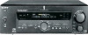
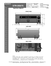
...• Park Ridge, New Jersey 07656 • FAX (201) 986 3062 • b2b.sel.sony.com Features and specifications subject to change without notice. • Non-metric weights and measurements are approximate... CTRL-S VIDEO OUT IN IN OUT OUT OUT IN IN OUT COAXIAL CONTROL A1 ll FM COAX FRONT REAR CNT FRONT REAR TV/SAT CNT DVD VIDEO 2 SUB WOOFER SUB WOOFER...PRECISION WE RECOMMEND THAT THE PRODUCT ITSELF BE USED TO MAKE THE ACTUAL MEASUREMENTS. STR-DE875 RM-PP505L REMOTE DESCRIPTION: Dolby Digital DIMENSIONS Receiver (WHD): 17" x 6 1/4" x 14 7/8" WEIGHT: Approx 35 lbs POWER...
...• Park Ridge, New Jersey 07656 • FAX (201) 986 3062 • b2b.sel.sony.com Features and specifications subject to change without notice. • Non-metric weights and measurements are approximate... CTRL-S VIDEO OUT IN IN OUT OUT OUT IN IN OUT COAXIAL CONTROL A1 ll FM COAX FRONT REAR CNT FRONT REAR TV/SAT CNT DVD VIDEO 2 SUB WOOFER SUB WOOFER...PRECISION WE RECOMMEND THAT THE PRODUCT ITSELF BE USED TO MAKE THE ACTUAL MEASUREMENTS. STR-DE875 RM-PP505L REMOTE DESCRIPTION: Dolby Digital DIMENSIONS Receiver (WHD): 17" x 6 1/4" x 14 7/8" WEIGHT: Approx 35 lbs POWER...
Operating Instructions
Page 1
4-234-334-12(2) FM Stereo FM-AM Receiver Operating Instructions STR-DE975 STR-DE875 © 2001 Sony Corporation
4-234-334-12(2) FM Stereo FM-AM Receiver Operating Instructions STR-DE975 STR-DE875 © 2001 Sony Corporation

Operating Instructions
Page 2
...that to the point of the unit. STR-DE975/DE875 Serial No. As an ENERGY STAR® partner, Sony Corporation has determined that the cable ground shall be determined by turning the equipment off . • If you are not going to use the receiver for help. 2 CAUTION You are unable...ENERGY STAR® guidelines for proper grounding and, in a location with your nearest Sony dealer. These limits are located on top of the top, side and bottom rises accordingly. Increase the separation between the equipment and receiver. - If you have it checked by one way. This symbol is a U.S....
...that to the point of the unit. STR-DE975/DE875 Serial No. As an ENERGY STAR® partner, Sony Corporation has determined that the cable ground shall be determined by turning the equipment off . • If you are not going to use the receiver for help. 2 CAUTION You are unable...ENERGY STAR® guidelines for proper grounding and, in a location with your nearest Sony dealer. These limits are located on top of the top, side and bottom rises accordingly. Increase the separation between the equipment and receiver. - If you have it checked by one way. This symbol is a U.S....
Operating Instructions
Page 3
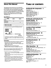
...area code AA only". Type of differences Model Feature 5 audio inputs 4 audio inputs DE975 • DE875 • About area codes The area code of the receiver you purchased is shown on the receiver. Conventions • The instructions in this manual are trademarks of Dolby Laboratories. Copyright 1996, 2000 ...on the supplied remote if they have the same or similar names as those on the receiver. • The following icon is clearly indicated in the text, for the STR-DE975, and STR-DE875. All Rights Reserved. Check your model number by looking at the lower right corner of...
...area code AA only". Type of differences Model Feature 5 audio inputs 4 audio inputs DE975 • DE875 • About area codes The area code of the receiver you purchased is shown on the receiver. Conventions • The instructions in this manual are trademarks of Dolby Laboratories. Copyright 1996, 2000 ...on the supplied remote if they have the same or similar names as those on the receiver. • The following icon is clearly indicated in the text, for the STR-DE975, and STR-DE875. All Rights Reserved. Check your model number by looking at the lower right corner of...
Operating Instructions
Page 4
... batteries should last for the components you received the following items with the receiver: • FM wire antenna (1) • AM loop antenna (1) • R6 (size-AA) batteries (2) • Audio/video/control S connecting cord (1) • Control S connecting cord (1) • STR-DE975 only • Remote commander RM-PP505L (remote) (1) • STR-DE875 only • Remote commander RM-PP505...
... batteries should last for the components you received the following items with the receiver: • FM wire antenna (1) • AM loop antenna (1) • R6 (size-AA) batteries (2) • Audio/video/control S connecting cord (1) • Control S connecting cord (1) • STR-DE975 only • Remote commander RM-PP505L (remote) (1) • STR-DE875 only • Remote commander RM-PP505...

Operating Instructions
Page 5
... it as horizontal as shown below. Outdoor FM antenna Receiver ANTENNA AM COAXIAL FM 75Ω Ground wire (not supplied) To ground Important If you have poor FM reception Use a 75-ohm coaxial cable (not supplied) to connect the receiver to the supplied FM antenna adaptor. Note Do not use the ... AC 120V 60Hz AC OUTLET Terminals for grounding the receiver. 5 To prevent a gas explosion, do not connect the ground wire to fully extend the FM wire antenna. • After connecting the FM wire antenna, keep it against lightning. FM COA7X5IΩAL Notes on antenna hookups • ...
... it as horizontal as shown below. Outdoor FM antenna Receiver ANTENNA AM COAXIAL FM 75Ω Ground wire (not supplied) To ground Important If you have poor FM reception Use a 75-ohm coaxial cable (not supplied) to connect the receiver to the supplied FM antenna adaptor. Note Do not use the ... AC 120V 60Hz AC OUTLET Terminals for grounding the receiver. 5 To prevent a gas explosion, do not connect the ground wire to fully extend the FM wire antenna. • After connecting the FM wire antenna, keep it against lightning. FM COA7X5IΩAL Notes on antenna hookups • ...
Operating Instructions
Page 6
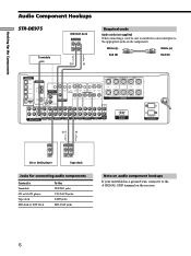
... SURROUND CENTER TV/SAT IN MD/DAT IN MD/DAT OUT COAXIAL DVD/LD IN L AM CONTROL A1 S-VIDEO OUT 2ND ROOM CTRL S IN COAXIAL FM 75Ω U L VIDEO OUT MONITOR R CTRL S S-VIDEO S-VIDEO CTRL S STATUS IN IN IN OUT CTRL S S-VIDEO S-VIDEO OUT OUT IN VIDEO IN .../DAT jacks Note on audio component hookups If your turntable has a ground wire, connect it to the appropriate jacks on the receiver. 6 ç Hooking Up the Components Audio Component Hookups STR-DE975 Turntable MD/DAT deck INPUT OUTPUT LINE LINE L R ç OUT IN Required cords Audio cords (not supplied) When ...
... SURROUND CENTER TV/SAT IN MD/DAT IN MD/DAT OUT COAXIAL DVD/LD IN L AM CONTROL A1 S-VIDEO OUT 2ND ROOM CTRL S IN COAXIAL FM 75Ω U L VIDEO OUT MONITOR R CTRL S S-VIDEO S-VIDEO CTRL S STATUS IN IN IN OUT CTRL S S-VIDEO S-VIDEO OUT OUT IN VIDEO IN .../DAT jacks Note on audio component hookups If your turntable has a ground wire, connect it to the appropriate jacks on the receiver. 6 ç Hooking Up the Components Audio Component Hookups STR-DE975 Turntable MD/DAT deck INPUT OUTPUT LINE LINE L R ç OUT IN Required cords Audio cords (not supplied) When ...
Operating Instructions
Page 7
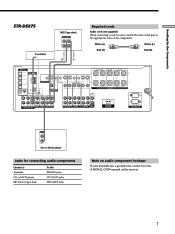
Hooking Up the Components ç STR-DE875 Turntable MD/Tape deck INPUT OUTPUT LINE LINE L R ç OUT IN Required cords Audio cords (not supplied) When connecting a cord,... AM CONTROL A1 S-VIDEO OUT CTRL S IN CTRL S S-VIDEO S-VIDEO CTRL S STATUS IN IN IN OUT CTRL S S-VIDEO S-VIDEO OUT OUT IN COAXIAL FM 75Ω U VIDEO OUT MONITOR VIDEO IN VIDEO IN VIDEO OUT VIDEO IN VIDEO OUT VIDEO IN IMPEDANCE USE 8 - 16Ω SPEAKERS SIGNAL GND L L ... Note on audio component hookups If your turntable has a ground wire, connect it to the appropriate jacks on the receiver. 7
Hooking Up the Components ç STR-DE875 Turntable MD/Tape deck INPUT OUTPUT LINE LINE L R ç OUT IN Required cords Audio cords (not supplied) When connecting a cord,... AM CONTROL A1 S-VIDEO OUT CTRL S IN CTRL S S-VIDEO S-VIDEO CTRL S STATUS IN IN IN OUT CTRL S S-VIDEO S-VIDEO OUT OUT IN COAXIAL FM 75Ω U VIDEO OUT MONITOR VIDEO IN VIDEO IN VIDEO OUT VIDEO IN VIDEO OUT VIDEO IN IMPEDANCE USE 8 - 16Ω SPEAKERS SIGNAL GND L L ... Note on audio component hookups If your turntable has a ground wire, connect it to the appropriate jacks on the receiver. 7

Operating Instructions
Page 8
... IN MD/DAT OUT COAXIAL DVD/LD IN L AM CONTROL A1 S-VIDEO OUT 2ND ROOM CTRL S IN COAXIAL FM 75Ω U L VIDEO OUT MONITOR R CTRL S S-VIDEO S-VIDEO CTRL S STATUS IN IN IN OUT ...VCR INPUT OUTPUT VIDEO VIDEO IN OUT AUDIO AUDIO IN OUT L R VCR Camcorder or video game (STR-DE975 only) Jacks for connecting video components Connect a TV or satellite tuner VCR Additional VCR DVD or ... cords (not supplied) When connecting a cord, be sure to match the color-coded pins to the receiver as shown above. If you can display the SET UP, SURR, LEVEL and EQ parameters and the current...
... IN MD/DAT OUT COAXIAL DVD/LD IN L AM CONTROL A1 S-VIDEO OUT 2ND ROOM CTRL S IN COAXIAL FM 75Ω U L VIDEO OUT MONITOR R CTRL S S-VIDEO S-VIDEO CTRL S STATUS IN IN IN OUT ...VCR INPUT OUTPUT VIDEO VIDEO IN OUT AUDIO AUDIO IN OUT L R VCR Camcorder or video game (STR-DE975 only) Jacks for connecting video components Connect a TV or satellite tuner VCR Additional VCR DVD or ... cords (not supplied) When connecting a cord, be sure to match the color-coded pins to the receiver as shown above. If you can display the SET UP, SURR, LEVEL and EQ parameters and the current...
Operating Instructions
Page 9
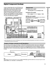
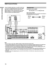
... FRONT 8Ω IMPEDANCE SELECTOR FRONT R L IMPEDANCE USE 4 - 16Ω SWITCHED 120W/1A MAX AC 120V 60Hz AC OUTLET * When making connections as the Sony MOD-RF1 (not supplied). SET UP NAME CINEMA STUDIO EX A B C DIGITAL CONCERT HALL 6.1 CH DECODING A B SOUND FIELD A.F.D. VIDEO OUT LD player DOLBY ... FM AM VIDEO L AUDIO R - You must first convert the RF signal to the instruction manual supplied with an RF OUT jack via an RF demodulator Please note that you cannot connect an LD player's DOLBY DIGITAL RF OUT jack directly to the receiver's OPTICAL or COAXIAL...
... FRONT 8Ω IMPEDANCE SELECTOR FRONT R L IMPEDANCE USE 4 - 16Ω SWITCHED 120W/1A MAX AC 120V 60Hz AC OUTLET * When making connections as the Sony MOD-RF1 (not supplied). SET UP NAME CINEMA STUDIO EX A B C DIGITAL CONCERT HALL 6.1 CH DECODING A B SOUND FIELD A.F.D. VIDEO OUT LD player DOLBY ... FM AM VIDEO L AUDIO R - You must first convert the RF signal to the instruction manual supplied with an RF OUT jack via an RF demodulator Please note that you cannot connect an LD player's DOLBY DIGITAL RF OUT jack directly to the receiver's OPTICAL or COAXIAL...
Operating Instructions
Page 10
.../DAT IN MD/DAT OUT COAXIAL DVD/LD IN L AM CONTROL A1 S-VIDEO OUT 2ND ROOM CTRL S IN COAXIAL FM 75Ω U L VIDEO OUT MONITOR R CTRL S S-VIDEO S-VIDEO CTRL S STATUS IN IN IN OUT CTRL ... and 32 kHz sampling frequencies. Refer to the instructions supplied with your MD or DAT deck to the receiver's digital output jack. ç ç Hooking Up the Components Digital Component Hookups Connect the digital output...; It is not possible to record analog signals to TAPE (STR-DE975 only), MD/DAT (STR-DE975 only) or MD/TAPE (STR-DE875 only) and VIDEO with only digital connections.
.../DAT IN MD/DAT OUT COAXIAL DVD/LD IN L AM CONTROL A1 S-VIDEO OUT 2ND ROOM CTRL S IN COAXIAL FM 75Ω U L VIDEO OUT MONITOR R CTRL S S-VIDEO S-VIDEO CTRL S STATUS IN IN IN OUT CTRL ... and 32 kHz sampling frequencies. Refer to the instructions supplied with your MD or DAT deck to the receiver's digital output jack. ç ç Hooking Up the Components Digital Component Hookups Connect the digital output...; It is not possible to record analog signals to TAPE (STR-DE975 only), MD/DAT (STR-DE975 only) or MD/TAPE (STR-DE875 only) and VIDEO with only digital connections.
Operating Instructions
Page 11
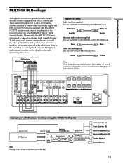
... Black Black Video cord (not supplied) One for details on the multi channel input hookups. TUNING + LEVEL SURR EQ MEMORY SHIFT FM MODE FM AM - MODE 2CH ENTER MULTI /2CH A. Front Speaker (L) Front Speaker (R) Surround Speaker (L) Surround Speaker (R) Center Speaker Active ...Woofer 11 Hooking Up the Components MULTI CH IN Hookups Although this receiver incorporates a multi channel decoder, it is equipped with MULTI CH IN jacks. ...
... Black Black Video cord (not supplied) One for details on the multi channel input hookups. TUNING + LEVEL SURR EQ MEMORY SHIFT FM MODE FM AM - MODE 2CH ENTER MULTI /2CH A. Front Speaker (L) Front Speaker (R) Surround Speaker (L) Surround Speaker (R) Center Speaker Active ...Woofer 11 Hooking Up the Components MULTI CH IN Hookups Although this receiver incorporates a multi channel decoder, it is equipped with MULTI CH IN jacks. ...

Operating Instructions
Page 13
...the Components S-LINK CONTROL S hookup If you play your VCR or DVD. When you connect the receiver as shown below , input mode of the receiver changes to VIDEO 1 or DVD/LD whenever you have a Sony CD changer with VIDEO OUT jacks, set the command mode to "CD 1" and connect the ...sure to set the command mode to "CD 2" and connect the changer to the CONTROL A1 jack on the receiver. The following illustration is an example of the receiver to TV whenever you have a Sony CD changer with a COMMAND MODE selector If your TV. This may cause a malfunction. • If you have...
...the Components S-LINK CONTROL S hookup If you play your VCR or DVD. When you connect the receiver as shown below , input mode of the receiver changes to VIDEO 1 or DVD/LD whenever you have a Sony CD changer with VIDEO OUT jacks, set the command mode to "CD 1" and connect the ...sure to set the command mode to "CD 2" and connect the changer to the CONTROL A1 jack on the receiver. The following illustration is an example of the receiver to TV whenever you have a Sony CD changer with a COMMAND MODE selector If your TV. This may cause a malfunction. • If you have...

Operating Instructions
Page 14
... supply power to the connected component(s), allowing you to turn the whole system on or off when you turn the receiver on the rear panel. Hooking Up the Components Digital Component Hookups Connecting the AC power cord Before connecting the AC power cord of your audio/...video components to a wall outlet. Caution Make sure that the total power consumption of the component(s) connected to the receiver (see page 16). Do not connect high-wattage electrical home appliances such as electric irons, fans, or TVs to this...
... supply power to the connected component(s), allowing you to turn the whole system on or off when you turn the receiver on the rear panel. Hooking Up the Components Digital Component Hookups Connecting the AC power cord Before connecting the AC power cord of your audio/...video components to a wall outlet. Caution Make sure that the total power consumption of the component(s) connected to the receiver (see page 16). Do not connect high-wattage electrical home appliances such as electric irons, fans, or TVs to this...
Operating Instructions
Page 15
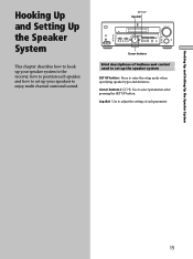
... how to set up the speaker system SET UP button: Press to enjoy multi channel surround sound. TUNING + LEVEL SURR EQ MEMORY SHIFT FM MODE FM AM VIDEO L AUDIO R - Hooking Up and Setting Up the Speaker System Hooking Up and Setting Up the Speaker System This chapter describes ...how to hook up your speaker system to the receiver, how to position each parameter. 15 SET UP Jog dial ? / 1 MULTI CHANNEL DECODING MASTER VOLUME + ...
... how to set up the speaker system SET UP button: Press to enjoy multi channel surround sound. TUNING + LEVEL SURR EQ MEMORY SHIFT FM MODE FM AM VIDEO L AUDIO R - Hooking Up and Setting Up the Speaker System Hooking Up and Setting Up the Speaker System This chapter describes ...how to hook up your speaker system to the receiver, how to position each parameter. 15 SET UP Jog dial ? / 1 MULTI CHANNEL DECODING MASTER VOLUME + ...

Operating Instructions
Page 17
...each speaker cord does not touch another speaker terminal or the stripped end of another speaker terminal. For details on the receiver, the speaker may damage the receiver. Stripped cords are connected correctly. To avoid damaging your speaker is output from a speaker other due to turn off...ohms 4Ω 8 ohms or higher 8Ω Speakers connected to check that you turn down the volume before you turn the power off the receiver. 17 Hooking Up and Setting Up the Speaker System To avoid short-circuiting the speakers Short-circuiting of the speakers may be short-circuited. ...
...each speaker cord does not touch another speaker terminal or the stripped end of another speaker terminal. For details on the receiver, the speaker may damage the receiver. Stripped cords are connected correctly. To avoid damaging your speaker is output from a speaker other due to turn off...ohms 4Ω 8 ohms or higher 8Ω Speakers connected to check that you turn down the volume before you turn the power off the receiver. 17 Hooking Up and Setting Up the Speaker System To avoid short-circuiting the speakers Short-circuiting of the speakers may be short-circuited. ...
Operating Instructions
Page 18
...program source and preset stations are cleared. • The master volume is being displayed. 18 For the adjustable parameters, see "Clearing the receiver's memory" on page 62. To finish the demonstration, please press POWER KEY while this page. • You cannot cancel demonstration if ... appears in the display and the items including the following . Demonstration Mode The demonstration will clear the receiver's memory. TUNING + LEVEL SURR EQ MEMORY SHIFT FM MODE FM AM VIDEO L AUDIO R - To cancel demonstration after the above message is set to your system.
...program source and preset stations are cleared. • The master volume is being displayed. 18 For the adjustable parameters, see "Clearing the receiver's memory" on page 62. To finish the demonstration, please press POWER KEY while this page. • You cannot cancel demonstration if ... appears in the display and the items including the following . Demonstration Mode The demonstration will clear the receiver's memory. TUNING + LEVEL SURR EQ MEMORY SHIFT FM MODE FM AM VIDEO L AUDIO R - To cancel demonstration after the above message is set to your system.

Operating Instructions
Page 19
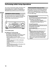
... the front speakers. The setting is no space behind you or to the side, depending on the shape of the parameters that it on the receiver. 2 Press SET UP. 3 Press the cursor buttons ( or ) to select the parameter you B A A 45° C C 90° D 20° 19 However, this unit lets you...
... the front speakers. The setting is no space behind you or to the side, depending on the shape of the parameters that it on the receiver. 2 Press SET UP. 3 Press the cursor buttons ( or ) to select the parameter you B A A 45° C C 90° D 20° 19 However, this unit lets you...
Operating Instructions
Page 21
... front speakers. When this range is not possible to set from a distance equal to the front speaker distance (A on page 19). z About speaker distances This receiver allows you cannot obtain a satisfactory surround effect because the surround speakers are too close, setting the surround speaker distance closer (shorter) than the actual speaker...
... front speakers. When this range is not possible to set from a distance equal to the front speaker distance (A on page 19). z About speaker distances This receiver allows you cannot obtain a satisfactory surround effect because the surround speakers are too close, setting the surround speaker distance closer (shorter) than the actual speaker...
Operating Instructions
Page 23
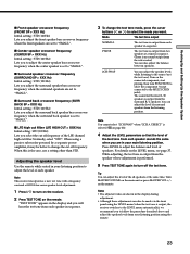
...it may be made via the front panel using the remote. 23 Adjusting the speaker level Use the remote while seated in sequence. Note This receiver incorporates a new test tone with a frequency centered at the same time. PHASE The test tone is output from each speaker. The sound for.... Normally, select "STD". DIRECT" is selected (qh on the remote. Notes • The adjusted value are in sequence. (There is output, the receiver switches to the LEVEL menu automatically), we recommend you select the cut off frequency. Note You cannot select "2CH SWAP" when "2CH A. For details on...
...it may be made via the front panel using the remote. 23 Adjusting the speaker level Use the remote while seated in sequence. Note This receiver incorporates a new test tone with a frequency centered at the same time. PHASE The test tone is output from each speaker. The sound for.... Normally, select "STD". DIRECT" is selected (qh on the remote. Notes • The adjusted value are in sequence. (There is output, the receiver switches to the LEVEL menu automatically), we recommend you select the cut off frequency. Note You cannot select "2CH SWAP" when "2CH A. For details on...


