Operating Instructions
Page 3
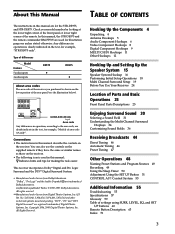
... 8Ω IMPEDANCE SELECTOR SWITCHED 120W/1A MAX AC 120V 60Hz AC OUTLET 4-XXX-XXX-XX AA Area code Any differences in operation, according to the area code, are for the STR-DE975, and STR-DE875. Hooking Up the Components 4 Unpacking 4 Antenna Hookups 5 Audio Component Hookups 6 Video Component Hookups 8 Digital... 25 Enjoying Surround Sound 30 Selecting a Sound Field 31 Understanding the Multi-Channel Surround Displays 34 Customizing Sound Fields 36 Receiving Broadcasts 44 Direct Tuning 46 Automatic Tuning 46 Preset Tuning 47 Other Operations 48 Naming Preset Stations and Program Sources 49 ...
... 8Ω IMPEDANCE SELECTOR SWITCHED 120W/1A MAX AC 120V 60Hz AC OUTLET 4-XXX-XXX-XX AA Area code Any differences in operation, according to the area code, are for the STR-DE975, and STR-DE875. Hooking Up the Components 4 Unpacking 4 Antenna Hookups 5 Audio Component Hookups 6 Video Component Hookups 8 Digital... 25 Enjoying Surround Sound 30 Selecting a Sound Field 31 Understanding the Multi-Channel Surround Displays 34 Customizing Sound Fields 36 Receiving Broadcasts 44 Direct Tuning 46 Automatic Tuning 46 Preset Tuning 47 Other Operations 48 Naming Preset Stations and Program Sources 49 ...
Operating Instructions
Page 4
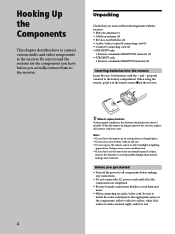
...components before you received the following items with the receiver: • FM wire antenna (1) • AM loop antenna (1) • R6 (size-AA) batteries (2) • Audio/video/control S connecting cord (1) • Control S connecting cord (1) • STR-DE975 only • Remote commander RM-PP505L (remote) (1) • STR-DE875 only •...to avoid hum and noise. • When connecting an audio/video cord, be sure to match the color-coded pins to the appropriate jacks on the receiver. When using the remote, point it at the remote sensor g on the components: yellow (video) to ...
...components before you received the following items with the receiver: • FM wire antenna (1) • AM loop antenna (1) • R6 (size-AA) batteries (2) • Audio/video/control S connecting cord (1) • Control S connecting cord (1) • STR-DE975 only • Remote commander RM-PP505L (remote) (1) • STR-DE875 only •...to avoid hum and noise. • When connecting an audio/video cord, be sure to match the color-coded pins to the appropriate jacks on the receiver. When using the remote, point it at the remote sensor g on the components: yellow (video) to ...
Operating Instructions
Page 6
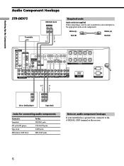
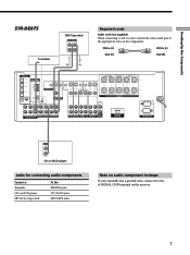
...Hooking Up the Components Audio Component Hookups STR-DE975 Turntable MD/DAT deck INPUT OUTPUT LINE LINE L R ç OUT IN Required cords Audio cords (not supplied) When connecting a cord, be sure to match the color-coded pins to the U SIGNAL GND terminal... on the components. White (L) White (L) Red (R) Red (R) DIGITAL OPTICAL DVD/LD IN ANTENNA SURROUND CENTER TV/SAT IN MD/DAT IN MD/DAT OUT COAXIAL DVD/LD IN L AM CONTROL A1 S-VIDEO OUT 2ND ROOM CTRL S IN COAXIAL FM... wire, connect it to the appropriate jacks on the receiver. 6
...Hooking Up the Components Audio Component Hookups STR-DE975 Turntable MD/DAT deck INPUT OUTPUT LINE LINE L R ç OUT IN Required cords Audio cords (not supplied) When connecting a cord, be sure to match the color-coded pins to the U SIGNAL GND terminal... on the components. White (L) White (L) Red (R) Red (R) DIGITAL OPTICAL DVD/LD IN ANTENNA SURROUND CENTER TV/SAT IN MD/DAT IN MD/DAT OUT COAXIAL DVD/LD IN L AM CONTROL A1 S-VIDEO OUT 2ND ROOM CTRL S IN COAXIAL FM... wire, connect it to the appropriate jacks on the receiver. 6
Operating Instructions
Page 7
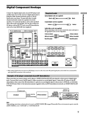
...AM CONTROL A1 S-VIDEO OUT CTRL S IN CTRL S S-VIDEO S-VIDEO CTRL S STATUS IN IN IN OUT CTRL S S-VIDEO S-VIDEO OUT OUT IN COAXIAL FM 75Ω U VIDEO OUT MONITOR VIDEO IN VIDEO IN VIDEO OUT VIDEO IN VIDEO OUT VIDEO IN IMPEDANCE USE 8 - 16Ω SPEAKERS SIGNAL GND L .../TAPE jacks Note on audio component hookups If your turntable has a ground wire, connect it to the appropriate jacks on the receiver. 7 Hooking Up the Components ç STR-DE875 Turntable MD/Tape deck INPUT OUTPUT LINE LINE L R ç OUT IN Required cords Audio cords (not supplied) When connecting...
...AM CONTROL A1 S-VIDEO OUT CTRL S IN CTRL S S-VIDEO S-VIDEO CTRL S STATUS IN IN IN OUT CTRL S S-VIDEO S-VIDEO OUT OUT IN COAXIAL FM 75Ω U VIDEO OUT MONITOR VIDEO IN VIDEO IN VIDEO OUT VIDEO IN VIDEO OUT VIDEO IN IMPEDANCE USE 8 - 16Ω SPEAKERS SIGNAL GND L .../TAPE jacks Note on audio component hookups If your turntable has a ground wire, connect it to the appropriate jacks on the receiver. 7 Hooking Up the Components ç STR-DE875 Turntable MD/Tape deck INPUT OUTPUT LINE LINE L R ç OUT IN Required cords Audio cords (not supplied) When connecting...

Operating Instructions
Page 8
.../video cords (not supplied) When connecting a cord, be sure to match the color-coded pins to the TV/SAT VIDEO IN jack on the receiver. Yellow (video) White (L/audio) Red (R/audio) Yellow (video) White (L/audio) ... MD/DAT OUT COAXIAL DVD/LD IN L AM CONTROL A1 S-VIDEO OUT 2ND ROOM CTRL S IN COAXIAL FM 75Ω U L VIDEO OUT MONITOR R CTRL S S-VIDEO S-VIDEO CTRL S STATUS IN IN IN ...INPUT OUTPUT VIDEO VIDEO IN OUT AUDIO AUDIO IN OUT L R VCR Camcorder or video game (STR-DE975 only) Jacks for connecting video components Connect a TV or satellite tuner VCR Additional VCR DVD ...
.../video cords (not supplied) When connecting a cord, be sure to match the color-coded pins to the TV/SAT VIDEO IN jack on the receiver. Yellow (video) White (L/audio) Red (R/audio) Yellow (video) White (L/audio) ... MD/DAT OUT COAXIAL DVD/LD IN L AM CONTROL A1 S-VIDEO OUT 2ND ROOM CTRL S IN COAXIAL FM 75Ω U L VIDEO OUT MONITOR R CTRL S S-VIDEO S-VIDEO CTRL S STATUS IN IN IN ...INPUT OUTPUT VIDEO VIDEO IN OUT AUDIO AUDIO IN OUT L R VCR Camcorder or video game (STR-DE975 only) Jacks for connecting video components Connect a TV or satellite tuner VCR Additional VCR DVD ...
Operating Instructions
Page 9
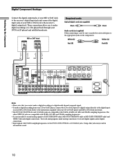
... 16Ω SWITCHED 120W/1A MAX AC 120V 60Hz AC OUTLET * When making connections as the Sony MOD-RF1 (not supplied). MODE 2CH ENTER MULTI /2CH A. TUNING + LEVEL SURR EQ MEMORY SHIFT FM MODE FM AM VIDEO L AUDIO R - Hooking Up the Components Digital Component Hookups Connect the digital output jacks ... To enjoy full effect of LD player connected via an RF demodulator, such as shown above, be sure to match the color-coded pins to the receiver's digital input jacks. You must first convert the RF signal to bring the multi channel surround sound of a movie theater into ...
... 16Ω SWITCHED 120W/1A MAX AC 120V 60Hz AC OUTLET * When making connections as the Sony MOD-RF1 (not supplied). MODE 2CH ENTER MULTI /2CH A. TUNING + LEVEL SURR EQ MEMORY SHIFT FM MODE FM AM VIDEO L AUDIO R - Hooking Up the Components Digital Component Hookups Connect the digital output jacks ... To enjoy full effect of LD player connected via an RF demodulator, such as shown above, be sure to match the color-coded pins to the receiver's digital input jacks. You must first convert the RF signal to bring the multi channel surround sound of a movie theater into ...
Operating Instructions
Page 10
...COAXIAL DVD/LD IN L AM CONTROL A1 S-VIDEO OUT 2ND ROOM CTRL S IN COAXIAL FM 75Ω U L VIDEO OUT MONITOR R CTRL S S-VIDEO S-VIDEO CTRL S STATUS.... Refer to the instructions supplied with your MD or DAT deck to the receiver's digital output jack. MD or DAT deck DIGITAL OPTICAL IN INPUT OUTPUT LINE...Audio cords (not supplied) When connecting a cord, be sure to match the color-coded pins to the appropriate jacks on your DVD (or LD player) and satellite broadcasts....(STR-DE975 only), MD/DAT (STR-DE975 only) or MD/TAPE (STR-DE875 only) and VIDEO with only digital connections.
...COAXIAL DVD/LD IN L AM CONTROL A1 S-VIDEO OUT 2ND ROOM CTRL S IN COAXIAL FM 75Ω U L VIDEO OUT MONITOR R CTRL S S-VIDEO S-VIDEO CTRL S STATUS.... Refer to the instructions supplied with your MD or DAT deck to the receiver's digital output jack. MD or DAT deck DIGITAL OPTICAL IN INPUT OUTPUT LINE...Audio cords (not supplied) When connecting a cord, be sure to match the color-coded pins to the appropriate jacks on your DVD (or LD player) and satellite broadcasts....(STR-DE975 only), MD/DAT (STR-DE975 only) or MD/TAPE (STR-DE875 only) and VIDEO with only digital connections.
Operating Instructions
Page 12
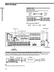
...Up the Components Required cords Audio cords (not supplied) When connecting a cord, be sure to match the color-coded pins to a stereo amplifier located in another room. TUNING + LEVEL SURR EQ MEMORY SHIFT FM MODE FM AM SET UP NAME CINEMA STUDIO EX A B C DIGITAL CONCERT HALL 6.1 CH DECODING A B SOUND FIELD... 2 R AUDIO OUT AUDIO IN VIDEO 1 SUB WOOFER 4Ω FRONT 8Ω IMPEDANCE SELECTOR FRONT R L IMPEDANCE USE 4 - 16Ω 2ND ROOM (STR-DE975 only) SWITCHED 120W/1A MAX AC 120V 60Hz AC OUTLET b To a wall outlet Example of a 2nd room hookup using the 2ND ROOM jacks...
...Up the Components Required cords Audio cords (not supplied) When connecting a cord, be sure to match the color-coded pins to a stereo amplifier located in another room. TUNING + LEVEL SURR EQ MEMORY SHIFT FM MODE FM AM SET UP NAME CINEMA STUDIO EX A B C DIGITAL CONCERT HALL 6.1 CH DECODING A B SOUND FIELD... 2 R AUDIO OUT AUDIO IN VIDEO 1 SUB WOOFER 4Ω FRONT 8Ω IMPEDANCE SELECTOR FRONT R L IMPEDANCE USE 4 - 16Ω 2ND ROOM (STR-DE975 only) SWITCHED 120W/1A MAX AC 120V 60Hz AC OUTLET b To a wall outlet Example of a 2nd room hookup using the 2ND ROOM jacks...

Operating Instructions
Page 44
... you want , you can enter a frequency of the station you want directly by entering its 2-character code (see page 47). Up to 30 FM or AM stations can preset them to the receiver (see page 47). Before you begin, make sure you can be preset. Preset Tuning After you have... : • Connected an FM and AM antenna to preset selected stations. The receiver will also scan all available stations in stations using the numeric buttons on the remote (see page 46). Receiving Broadcasts This chapter describes how to receive FM or AM broadcasts and how to the...
... you want , you can enter a frequency of the station you want directly by entering its 2-character code (see page 47). Up to 30 FM or AM stations can preset them to the receiver (see page 47). Before you begin, make sure you can be preset. Preset Tuning After you have... : • Connected an FM and AM antenna to preset selected stations. The receiver will also scan all available stations in stations using the numeric buttons on the remote (see page 46). Receiving Broadcasts This chapter describes how to receive FM or AM broadcasts and how to the...

Operating Instructions
Page 47
...follows: nA1˜A2˜...˜A0˜B1˜B2˜...˜B0N nC0˜...C2˜C1N Using the preset codes 1 Rotate FUNCTION to another station. The last received station is tuned in the display. 5 Select a preset number by performing steps on the supplied remote. To change a ...preset number to select the tuner. Before tuning to preset stations, be sure to receive broadcasts" on page 45. "MEMORY" appears in this section, see "Brief descriptions of the station you want to the number. Each time you ...
...follows: nA1˜A2˜...˜A0˜B1˜B2˜...˜B0N nC0˜...C2˜C1N Using the preset codes 1 Rotate FUNCTION to another station. The last received station is tuned in the display. 5 Select a preset number by performing steps on the supplied remote. To change a ...preset number to select the tuner. Before tuning to preset stations, be sure to receive broadcasts" on page 45. "MEMORY" appears in this section, see "Brief descriptions of the station you want to the number. Each time you ...
Operating Instructions
Page 58
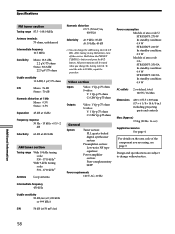
...code of area code CA: STR-DE975: 350 VA In standby condition: 0.9 W STR-DE875: 340 VA In standby condition: 0.9 W AC outlets 2 switched, total 120 W/1A Max Dimensions 430 × 157.5 × 369 mm (17 × 6 1/8 × 14 4/8 in any AM station, turn off the receiver... tuning interval to 10 kHz, repeat the procedure. Specifications FM tuner section Tuning range 87.5 - 108.0 MHz Antenna terminals 75 ohms,...75 ohms Stereo: 38.3 dBf 22.5 µV/75 ohms Usable sensitivity 11.2 dBf, 1 µV/75 ohms S/N Mono: 76 dB Stereo: 70 dB Harmonic distortion at 1 kHz Mono: 0.3% Stereo: 0.5%...
...code of area code CA: STR-DE975: 350 VA In standby condition: 0.9 W STR-DE875: 340 VA In standby condition: 0.9 W AC outlets 2 switched, total 120 W/1A Max Dimensions 430 × 157.5 × 369 mm (17 × 6 1/8 × 14 4/8 in any AM station, turn off the receiver... tuning interval to 10 kHz, repeat the procedure. Specifications FM tuner section Tuning range 87.5 - 108.0 MHz Antenna terminals 75 ohms,...75 ohms Stereo: 38.3 dBf 22.5 µV/75 ohms Usable sensitivity 11.2 dBf, 1 µV/75 ohms S/N Mono: 76 dB Stereo: 70 dB Harmonic distortion at 1 kHz Mono: 0.3% Stereo: 0.5%...
Operating Instructions
Page 66
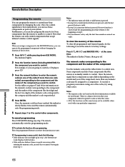
... the indicator slowly flashes twice and the remote automatically exits the programming mode. 5 Repeat steps 1 to 4 to control non-Sony components by changing the code. at the same time. Additional Information 66 To cancel programming Press USE MODE during any step. Press the programmed button to control... player, press CD. 3 Press the numeric buttons to enter the numeric code (or one of the codes if more than one of the functions on the latest information available for information on the model and year of the receiver. 1 Press AV ?/1 while pressing down USE MODE. Notes •...
... the indicator slowly flashes twice and the remote automatically exits the programming mode. 5 Repeat steps 1 to 4 to control non-Sony components by changing the code. at the same time. Additional Information 66 To cancel programming Press USE MODE during any step. Press the programmed button to control... player, press CD. 3 Press the numeric buttons to enter the numeric code (or one of the codes if more than one of the functions on the latest information available for information on the model and year of the receiver. 1 Press AV ?/1 while pressing down USE MODE. Notes •...

Operating Instructions
Page 68
... 68 VOL + n N MUTING X D. Remote Button Description To control a DVD player Maker Code(s) SONY 401 PANASONIC 402, 406 PHILIPS 407 PIONEER 403 TOSHIBA 404 DENON 405 To control a TV Maker SONY DAEWOO FISHER GOLDSTAR GRUNDIG HITACHI ITT/NOKIA JVC MAGNAVOX MITSUBISHI/MGA NEC PANASONIC PHILIPS PIONEER RCA/PROSCAN...544 508, 545 535 523, 536, 537, 538 530, 537, 539 535, 540, 541 542, 543 To control a satellite tuner or cable box Maker Code(s) SONY 801, 802, 803 JERROLD/G.I. 806, 807, 808, 809, 810, 811, 812, 813, 814 PANASONIC 818 RCA 804, 805 S. ATLANTA 815, 816,...
... 68 VOL + n N MUTING X D. Remote Button Description To control a DVD player Maker Code(s) SONY 401 PANASONIC 402, 406 PHILIPS 407 PIONEER 403 TOSHIBA 404 DENON 405 To control a TV Maker SONY DAEWOO FISHER GOLDSTAR GRUNDIG HITACHI ITT/NOKIA JVC MAGNAVOX MITSUBISHI/MGA NEC PANASONIC PHILIPS PIONEER RCA/PROSCAN...544 508, 545 535 523, 536, 537, 538 530, 537, 539 535, 540, 541 542, 543 To control a satellite tuner or cable box Maker Code(s) SONY 801, 802, 803 JERROLD/G.I. 806, 807, 808, 809, 810, 811, 812, 813, 814 PANASONIC 818 RCA 804, 805 S. ATLANTA 815, 816,...

Operating Instructions
Page 69
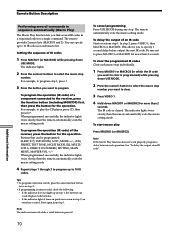
... • You can program up to be sufficient. z To activate the function after programming. The indicator lights twice slowly and the learned code is completed successfully, the indicator slowly flashes twice and the remote automatically exits the learning mode. At the same time, press ?/1, AV ...MONITOR function. The indicator turns off while a valid button is pressed, then blinks slowly. 4 Point the remote control code receiver section of the remote toward the receiver/transmitter on the remote control to be learned. 5-15 cm 5 Press the appropriate button on the remote control to 80...
... • You can program up to be sufficient. z To activate the function after programming. The indicator lights twice slowly and the learned code is completed successfully, the indicator slowly flashes twice and the remote automatically exits the learning mode. At the same time, press ?/1, AV ...MONITOR function. The indicator turns off while a valid button is pressed, then blinks slowly. 4 Point the remote control code receiver section of the remote toward the receiver/transmitter on the remote control to be learned. 5-15 cm 5 Press the appropriate button on the remote control to 80...
Operating Instructions
Page 70
...; To program a function switch, press the same function button twice in which the IR code you want to play Press MACRO1 (or MACRO2). The remote automatically exits the macro setting mode. See "To delay the output of the receiver, press the button for the operation. The remote provides 2 macro lists (MACRO1 and...
...; To program a function switch, press the same function button twice in which the IR code you want to play Press MACRO1 (or MACRO2). The remote automatically exits the macro setting mode. See "To delay the output of the receiver, press the button for the operation. The remote provides 2 macro lists (MACRO1 and...


