Operating Instructions
Page 6
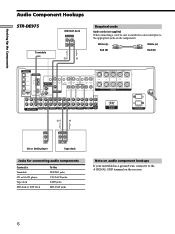
... SURROUND CENTER TV/SAT IN MD/DAT IN MD/DAT OUT COAXIAL DVD/LD IN L AM CONTROL A1 S-VIDEO OUT 2ND ROOM CTRL S IN COAXIAL FM 75Ω U L VIDEO OUT MONITOR R CTRL S S-VIDEO S-VIDEO CTRL S STATUS IN IN IN OUT CTRL S S-VIDEO S-VIDEO OUT OUT IN VIDEO ... on audio component hookups If your turntable has a ground wire, connect it to the appropriate jacks on the receiver. 6 ç Hooking Up the Components Audio Component Hookups STR-DE975 Turntable MD/DAT deck INPUT OUTPUT LINE LINE L R ç OUT IN Required cords Audio cords (not supplied) When connecting a cord, be...
... SURROUND CENTER TV/SAT IN MD/DAT IN MD/DAT OUT COAXIAL DVD/LD IN L AM CONTROL A1 S-VIDEO OUT 2ND ROOM CTRL S IN COAXIAL FM 75Ω U L VIDEO OUT MONITOR R CTRL S S-VIDEO S-VIDEO CTRL S STATUS IN IN IN OUT CTRL S S-VIDEO S-VIDEO OUT OUT IN VIDEO ... on audio component hookups If your turntable has a ground wire, connect it to the appropriate jacks on the receiver. 6 ç Hooking Up the Components Audio Component Hookups STR-DE975 Turntable MD/DAT deck INPUT OUTPUT LINE LINE L R ç OUT IN Required cords Audio cords (not supplied) When connecting a cord, be...
Operating Instructions
Page 7
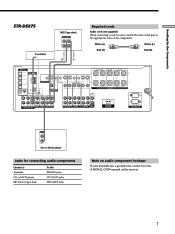
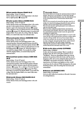
Hooking Up the Components ç STR-DE875 Turntable MD/Tape deck INPUT OUTPUT LINE LINE L R ç OUT IN Required cords Audio cords (not...CTRL S IN CTRL S S-VIDEO S-VIDEO CTRL S STATUS IN IN IN OUT CTRL S S-VIDEO S-VIDEO OUT OUT IN COAXIAL FM 75Ω U VIDEO OUT MONITOR VIDEO IN VIDEO IN VIDEO OUT VIDEO IN VIDEO OUT VIDEO IN IMPEDANCE USE 8 - 16...; IMPEDANCE SELECTOR FRONT R L IMPEDANCE USE 4 - 16Ω SWITCHED 120W/1A MAX AC 120V 60Hz AC OUTLET OUTPUT LINE L R CD or SACD player Jacks for connecting audio components Connect a Turntable CD or SACD player MD deck or...
Hooking Up the Components ç STR-DE875 Turntable MD/Tape deck INPUT OUTPUT LINE LINE L R ç OUT IN Required cords Audio cords (not...CTRL S IN CTRL S S-VIDEO S-VIDEO CTRL S STATUS IN IN IN OUT CTRL S S-VIDEO S-VIDEO OUT OUT IN COAXIAL FM 75Ω U VIDEO OUT MONITOR VIDEO IN VIDEO IN VIDEO OUT VIDEO IN VIDEO OUT VIDEO IN IMPEDANCE USE 8 - 16...; IMPEDANCE SELECTOR FRONT R L IMPEDANCE USE 4 - 16Ω SWITCHED 120W/1A MAX AC 120V 60Hz AC OUTLET OUTPUT LINE L R CD or SACD player Jacks for connecting audio components Connect a Turntable CD or SACD player MD deck or...

Operating Instructions
Page 8
... the receiver. z When using the S-video jacks instead of the video jacks Your monitor must also be output through the video jacks. In this case, do not connect the TV's video output jack... IN MD/DAT OUT COAXIAL DVD/LD IN L AM CONTROL A1 S-VIDEO OUT 2ND ROOM CTRL S IN COAXIAL FM 75Ω U L VIDEO OUT MONITOR R CTRL S S-VIDEO S-VIDEO CTRL S STATUS IN IN IN OUT... VIDEO IN TV monitor INPUT OUTPUT VIDEO VIDEO IN OUT AUDIO AUDIO IN OUT L R VCR INPUT OUTPUT VIDEO VIDEO IN OUT AUDIO AUDIO IN OUT L R VCR Camcorder or video game (STR-DE975 only) Jacks for connecting...
... the receiver. z When using the S-video jacks instead of the video jacks Your monitor must also be output through the video jacks. In this case, do not connect the TV's video output jack... IN MD/DAT OUT COAXIAL DVD/LD IN L AM CONTROL A1 S-VIDEO OUT 2ND ROOM CTRL S IN COAXIAL FM 75Ω U L VIDEO OUT MONITOR R CTRL S S-VIDEO S-VIDEO CTRL S STATUS IN IN IN OUT... VIDEO IN TV monitor INPUT OUTPUT VIDEO VIDEO IN OUT AUDIO AUDIO IN OUT L R VCR INPUT OUTPUT VIDEO VIDEO IN OUT AUDIO AUDIO IN OUT L R VCR Camcorder or video game (STR-DE975 only) Jacks for connecting...
Operating Instructions
Page 9
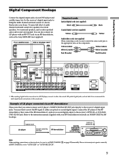
...RF demodulator, then connect the RF demodulator's optical or coaxial digital output to the receiver's digital input jacks. TUNING + LEVEL SURR EQ MEMORY SHIFT FM MODE FM AM VIDEO L AUDIO R - The receiver may not operate correctly if INPUT MODE is recommended to make digital ...IMPEDANCE SELECTOR FRONT R L IMPEDANCE USE 4 - 16Ω SWITCHED 120W/1A MAX AC 120V 60Hz AC OUTLET * When making connections as the Sony MOD-RF1 (not supplied). VIDEO OUT LD player DOLBY DIGITAL RF OUT RF demodulator DDIGIGITITAALL DDVVDD//LLDDININ (C(COOAAXXIAIALL)) or (O(OPPTTICICAALL)) DVD/LD VIDEO ...
...RF demodulator, then connect the RF demodulator's optical or coaxial digital output to the receiver's digital input jacks. TUNING + LEVEL SURR EQ MEMORY SHIFT FM MODE FM AM VIDEO L AUDIO R - The receiver may not operate correctly if INPUT MODE is recommended to make digital ...IMPEDANCE SELECTOR FRONT R L IMPEDANCE USE 4 - 16Ω SWITCHED 120W/1A MAX AC 120V 60Hz AC OUTLET * When making connections as the Sony MOD-RF1 (not supplied). VIDEO OUT LD player DOLBY DIGITAL RF OUT RF demodulator DDIGIGITITAALL DDVVDD//LLDDININ (C(COOAAXXIAIALL)) or (O(OPPTTICICAALL)) DVD/LD VIDEO ...
Operating Instructions
Page 10
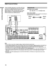
... COAXIAL DVD/LD IN L AM CONTROL A1 S-VIDEO OUT 2ND ROOM CTRL S IN COAXIAL FM 75Ω U L VIDEO OUT MONITOR R CTRL S S-VIDEO S-VIDEO CTRL S STATUS ...the receiver's digital output jack. ç ç Hooking Up the Components Digital Component Hookups Connect the digital output jacks of your MD or DAT deck to the receiver's ...OUTPUT LINE LINE L OUT R Required cords Optical digital cords (not supplied) Black Black Audio cords (not supplied) When connecting a cord, be sure to match the color-coded pins to TAPE (STR-DE975 only), MD/DAT (STR-DE975 only) or MD/TAPE (STR-DE875...
... COAXIAL DVD/LD IN L AM CONTROL A1 S-VIDEO OUT 2ND ROOM CTRL S IN COAXIAL FM 75Ω U L VIDEO OUT MONITOR R CTRL S S-VIDEO S-VIDEO CTRL S STATUS ...the receiver's digital output jack. ç ç Hooking Up the Components Digital Component Hookups Connect the digital output jacks of your MD or DAT deck to the receiver's ...OUTPUT LINE LINE L OUT R Required cords Optical digital cords (not supplied) Black Black Audio cords (not supplied) When connecting a cord, be sure to match the color-coded pins to TAPE (STR-DE975 only), MD/DAT (STR-DE975 only) or MD/TAPE (STR-DE875...
Operating Instructions
Page 11
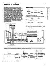
... SURROUND CENTER TV/SAT IN MD/DAT IN MD/DAT OUT COAXIAL DVD/LD IN L AM CONTROL A1 S-VIDEO OUT 2ND ROOM CTRL S IN COAXIAL FM 75Ω U L VIDEO OUT MONITOR R CTRL S S-VIDEO S-VIDEO CTRL S STATUS IN IN IN OUT CTRL S S-VIDEO S-VIDEO OUT OUT IN VIDEO IN VIDEO IN... five speakers (two front speakers, two surround speakers, and a center speaker) and a sub woofer. Hooking Up the Components MULTI CH IN Hookups Although this receiver incorporates a multi channel decoder, it is equipped with MULTI CH OUTPUT jacks, you can be used to connect an external multi channel decoder.
... SURROUND CENTER TV/SAT IN MD/DAT IN MD/DAT OUT COAXIAL DVD/LD IN L AM CONTROL A1 S-VIDEO OUT 2ND ROOM CTRL S IN COAXIAL FM 75Ω U L VIDEO OUT MONITOR R CTRL S S-VIDEO S-VIDEO CTRL S STATUS IN IN IN OUT CTRL S S-VIDEO S-VIDEO OUT OUT IN VIDEO IN VIDEO IN... five speakers (two front speakers, two surround speakers, and a center speaker) and a sub woofer. Hooking Up the Components MULTI CH IN Hookups Although this receiver incorporates a multi channel decoder, it is equipped with MULTI CH OUTPUT jacks, you can be used to connect an external multi channel decoder.
Operating Instructions
Page 12
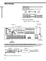
... of a 2nd room hookup using the 2ND ROOM jacks (STR-DE975 only) You can use the 2ND ROOM jacks to output the audio signal of the selected component to a stereo amplifier located in another room. AUDIO OUT PRESET - TUNING + LEVEL SURR EQ MEMORY SHIFT FM MODE FM AM SET UP NAME CINEMA STUDIO EX A B C DIGITAL...
... of a 2nd room hookup using the 2ND ROOM jacks (STR-DE975 only) You can use the 2ND ROOM jacks to output the audio signal of the selected component to a stereo amplifier located in another room. AUDIO OUT PRESET - TUNING + LEVEL SURR EQ MEMORY SHIFT FM MODE FM AM SET UP NAME CINEMA STUDIO EX A B C DIGITAL...

Operating Instructions
Page 13
... changer with VIDEO OUT jacks, set the command mode to "CD 1" and connect the changer to the CD jacks on the receiver. This may cause a malfunction. • If you have a Sony CD changer with a COMMAND MODE selector If your CD changer's COMMAND MODE selector can be set to CD 1, CD 2, or ... TV input mode will change the input mode of the receiver to TV whenever you operate your VCR or DVD. DVD player S-LINK IN * OUTPUT VIDEO OUT AUDIO OUT 13 Hooking Up the Components S-LINK CONTROL S hookup If you have a CONTROL A1 compatible Sony CD player, SACD player, tape deck, or MD deck...
... changer with VIDEO OUT jacks, set the command mode to "CD 1" and connect the changer to the CD jacks on the receiver. This may cause a malfunction. • If you have a Sony CD changer with a COMMAND MODE selector If your CD changer's COMMAND MODE selector can be set to CD 1, CD 2, or ... TV input mode will change the input mode of the receiver to TV whenever you operate your VCR or DVD. DVD player S-LINK IN * OUTPUT VIDEO OUT AUDIO OUT 13 Hooking Up the Components S-LINK CONTROL S hookup If you have a CONTROL A1 compatible Sony CD player, SACD player, tape deck, or MD deck...

Operating Instructions
Page 16
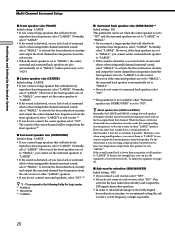
... cords are reversed, the sound will lack bass. • If you use speakers with low maximum input rating, adjust the volume carefully to avoid excessive output on the components: + to -. to + and - The remaining jack can connect an active sub woofer to connect a second active sub woofer. Be sure to match... SURROUND CENTER TV/SAT IN MD/DAT IN MD/DAT OUT COAXIAL DVD/LD IN L AM CONTROL A1 S-VIDEO OUT 2ND ROOM CTRL S IN COAXIAL FM 75Ω U L VIDEO OUT MONITOR R CTRL S S-VIDEO S-VIDEO CTRL S STATUS IN IN IN OUT CTRL S S-VIDEO S-VIDEO OUT OUT IN VIDEO IN VIDEO IN VIDEO...
... cords are reversed, the sound will lack bass. • If you use speakers with low maximum input rating, adjust the volume carefully to avoid excessive output on the components: + to -. to + and - The remaining jack can connect an active sub woofer to connect a second active sub woofer. Be sure to match... SURROUND CENTER TV/SAT IN MD/DAT IN MD/DAT OUT COAXIAL DVD/LD IN L AM CONTROL A1 S-VIDEO OUT 2ND ROOM CTRL S IN COAXIAL FM 75Ω U L VIDEO OUT MONITOR R CTRL S S-VIDEO S-VIDEO CTRL S STATUS IN IN IN OUT CTRL S S-VIDEO S-VIDEO OUT OUT IN VIDEO IN VIDEO IN VIDEO...

Operating Instructions
Page 17
...following precautions when connecting the speakers. After connecting all the components, speakers, and AC power cord, output a test tone to turn off the receiver. 17 To avoid damaging your speaker is output from a speaker while outputting a test tone or a test tone is Between 4 and 8 ohms 4Ω 8 ohms or... before you 're not sure of their impedance. (This information is usually printed on a label on the receiver, the speaker may damage the receiver. When you turn on outputting a test tone, see page 23. Make sure the stripped ends of another speaker terminal. If this , ...
...following precautions when connecting the speakers. After connecting all the components, speakers, and AC power cord, output a test tone to turn off the receiver. 17 To avoid damaging your speaker is output from a speaker while outputting a test tone or a test tone is Between 4 and 8 ohms 4Ω 8 ohms or... before you 're not sure of their impedance. (This information is usually printed on a label on the receiver, the speaker may damage the receiver. When you turn on outputting a test tone, see page 23. Make sure the stripped ends of another speaker terminal. If this , ...
Operating Instructions
Page 20
..., you feel a lack of surround effects when using multi channel surround sound, select "SMALL" to activate the bass redirection circuitry and output the front channel bass frequencies from that speaker. Normally, select "LARGE". However, if the surround speakers are also automatically set to "...8226; If you do not connect surround speakers, select "NO".*3 z *1~*3 correspond to the following Dolby Pro Logic modes *1 NORMAL *2 PHANTOM *3 3 STEREO x Surround back speaker size (SURR BACK)** Initial setting : NO This parameter can use the equalizer to "NO". On the other hand, if you ...
..., you feel a lack of surround effects when using multi channel surround sound, select "SMALL" to activate the bass redirection circuitry and output the front channel bass frequencies from that speaker. Normally, select "LARGE". However, if the surround speakers are also automatically set to "...8226; If you do not connect surround speakers, select "NO".*3 z *1~*3 correspond to the following Dolby Pro Logic modes *1 NORMAL *2 PHANTOM *3 3 STEREO x Surround back speaker size (SURR BACK)** Initial setting : NO This parameter can use the equalizer to "NO". On the other hand, if you ...
Operating Instructions
Page 21
...feet (4.5 meters) closer to your listening position (C on page 19). Adjusting these parameters while listening to the sound often results in the output of the sound from the listening position than the actual distance will create a fairly realistic sensation of distance. If you make the setting while...page 19). If you cannot fully enjoy the surround effect. When this range is exceeded, the display blinks. z About speaker distances This receiver allows you select either feet or meters as the unit of the overall sound may produce better bass. In other words, the speaker ...
...feet (4.5 meters) closer to your listening position (C on page 19). Adjusting these parameters while listening to the sound often results in the output of the sound from the listening position than the actual distance will create a fairly realistic sensation of distance. If you make the setting while...page 19). If you cannot fully enjoy the surround effect. When this range is exceeded, the display blinks. z About speaker distances This receiver allows you select either feet or meters as the unit of the overall sound may produce better bass. In other words, the speaker ...
Operating Instructions
Page 23
... to adjust the balance and level of the all speakers at 800 Hz for the front L/R speakers is no sound output from your listening position to turn on the receiver. 2 Press TEST TONE on page 28). 4 Adjust the LEVEL parameters so that the level of each speaker in sequence... each speaker. Note You cannot select "2CH SWAP" when "2CH A. While adjusting, the test tone is output from the speaker whose adjustment is output, the receiver switches to "SMALL". Turn on the LEVEL menu, see page 37. x Surround speaker crossover frequency (SURROUND SP > XXX Hz) Initial setting : STD...
... to adjust the balance and level of the all speakers at 800 Hz for the front L/R speakers is no sound output from your listening position to turn on the receiver. 2 Press TEST TONE on page 28). 4 Adjust the LEVEL parameters so that the level of each speaker in sequence... each speaker. Note You cannot select "2CH SWAP" when "2CH A. While adjusting, the test tone is output from the speaker whose adjustment is output, the receiver switches to "SMALL". Turn on the LEVEL menu, see page 37. x Surround speaker crossover frequency (SURROUND SP > XXX Hz) Initial setting : STD...
Operating Instructions
Page 24
... on the component that all the cords are fully inserted into the jacks on both the receiver and the component. TUNING + - TUNING + LEVEL SURR EQ MEMORY SHIFT FM MODE FM AM VIDEO L AUDIO R - If you encounter a problem that the headphones are not connected to the PHONES jack. ...on page 55. 24 Hooking Up and Setting Up the Speaker System Before You Use Your Receiver Checking the connections After connecting all of your components to the receiver, do not obtain normal sound output after performing this procedure, look for the connection is (are) fully inserted into the ...
... on the component that all the cords are fully inserted into the jacks on both the receiver and the component. TUNING + - TUNING + LEVEL SURR EQ MEMORY SHIFT FM MODE FM AM VIDEO L AUDIO R - If you encounter a problem that the headphones are not connected to the PHONES jack. ...on page 55. 24 Hooking Up and Setting Up the Speaker System Before You Use Your Receiver Checking the connections After connecting all of your components to the receiver, do not obtain normal sound output after performing this procedure, look for the connection is (are) fully inserted into the ...
Operating Instructions
Page 26
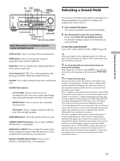
... Selects the FM band. For details, see "Receiving Broadcasts" starting from page 44. A.F.D. MODE button / indicator Press to activate the sound field selection mode (page 31). 2CH button / indicator Press to output sound from only the front (left and right) speakers. 8 MASTER VOLUME control ...A. DIRECT EQUALIZER MUTING INPUT MODE MODE FUNCTION 2ND ROOM 4 The following buttons operate the built-in the display and the FM stereo reception is improved. FM MODE button If "STEREO" flashes in tuner. A/B/C buttons Press to activate the CINEMA STUDIO EX A, B or C sound field (page 32). ...
... Selects the FM band. For details, see "Receiving Broadcasts" starting from page 44. A.F.D. MODE button / indicator Press to activate the sound field selection mode (page 31). 2CH button / indicator Press to output sound from only the front (left and right) speakers. 8 MASTER VOLUME control ...A. DIRECT EQUALIZER MUTING INPUT MODE MODE FUNCTION 2ND ROOM 4 The following buttons operate the built-in the display and the FM stereo reception is improved. FM MODE button If "STEREO" flashes in tuner. A/B/C buttons Press to activate the CINEMA STUDIO EX A, B or C sound field (page 32). ...

Operating Instructions
Page 27
... is set to "SOURCE", the sound from the selected component qa INPUT MODE button Press INPUT MODE to select the input mode for output to a stereo amplifier or speakers in tuner TUNER Turntable PHONO After selecting the component, turn on the component you press the button, the input mode ...deck MD or Tape deck TAPE (STR-DE975 only) MD/TAPE (STR-DE875 only) MD or DAT deck MD/DAT (STR-DE975 only) CD or SACD player CD/SACD Built in another video/audio source in combination with the video from front speakers (L/R) is not output when the receiver is no digital signals. Location ...
... is set to "SOURCE", the sound from the selected component qa INPUT MODE button Press INPUT MODE to select the input mode for output to a stereo amplifier or speakers in tuner TUNER Turntable PHONO After selecting the component, turn on the component you press the button, the input mode ...deck MD or Tape deck TAPE (STR-DE975 only) MD/TAPE (STR-DE875 only) MD or DAT deck MD/DAT (STR-DE975 only) CD or SACD player CD/SACD Built in another video/audio source in combination with the video from front speakers (L/R) is not output when the receiver is no digital signals. Location ...
Operating Instructions
Page 31
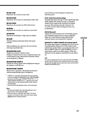
...programs are turned off Press A.F.D., 2CH or MULTI/2CH A. TUNING + LEVEL SURR EQ MEMORY SHIFT FM MODE FM AM VIDEO L AUDIO R - MODE 2CH ENTER MULTI /2CH A. Jog dial: Use to customize ... Tip When sound signals with the A logo. z You can enjoy powerful sounds as if in stereo automatically, and the sound field is possible to use the same signals. However, when a matrix decoder...and perform proper decoding (if necessary). EQ button: Press to output surround back signals. button: Press to set the receiver to output sound from only the front (left and right) speakers. MODE ...
...programs are turned off Press A.F.D., 2CH or MULTI/2CH A. TUNING + LEVEL SURR EQ MEMORY SHIFT FM MODE FM AM VIDEO L AUDIO R - MODE 2CH ENTER MULTI /2CH A. Jog dial: Use to customize ... Tip When sound signals with the A logo. z You can enjoy powerful sounds as if in stereo automatically, and the sound field is possible to use the same signals. However, when a matrix decoder...and perform proper decoding (if necessary). EQ button: Press to output surround back signals. button: Press to set the receiver to output sound from only the front (left and right) speakers. MODE ...
Operating Instructions
Page 33
... acoustics of audio signal being input (Dolby Digital, DTS, Dolby Pro Logic, or standard 2 channel stereo) and performs the proper decoding if necessary. x HEADPHONE (DIRECT) Outputs the analog signals without digital processing by the virtual speakers may cause increased noise in 2 channel... analog source. x GAME Obtains maximun audio impact from the sub woofer when the 2 CHANNEL mode is output from video game software. Standard 2 channel (stereo) sources completely bypass the sound field processing. When set to experience a theater like environment while listening through...
... acoustics of audio signal being input (Dolby Digital, DTS, Dolby Pro Logic, or standard 2 channel stereo) and performs the proper decoding if necessary. x HEADPHONE (DIRECT) Outputs the analog signals without digital processing by the virtual speakers may cause increased noise in 2 channel... analog source. x GAME Obtains maximun audio impact from the sub woofer when the 2 CHANNEL mode is output from video game software. Standard 2 channel (stereo) sources completely bypass the sound field processing. When set to experience a theater like environment while listening through...

Operating Instructions
Page 34
...: Surround Back (the surround back components obtained by 6.1 matrix decoding) Example: Recording format (Front/Surround): 3/2 Output channel: Surround speakers absent Sound Field: A.F.D. SW L C R STEREO MONO MEMORY a DTS MPEG SL SR SP.OFF D.RANGE EQ PRO LOGIC SSB SLEEP 1 OPT Lights up when... or NORMAL SURROUND sound fields are compatible with MPEG format. L.F.E. 7 Lights up when MPEG signals are set to show how the receiver downmixes the source sound (based on the source sound. Note Only the front 2 channels are selected. Enjoying Surround Sound Understanding the ...
...: Surround Back (the surround back components obtained by 6.1 matrix decoding) Example: Recording format (Front/Surround): 3/2 Output channel: Surround speakers absent Sound Field: A.F.D. SW L C R STEREO MONO MEMORY a DTS MPEG SL SR SP.OFF D.RANGE EQ PRO LOGIC SSB SLEEP 1 OPT Lights up when... or NORMAL SURROUND sound fields are compatible with MPEG format. L.F.E. 7 Lights up when MPEG signals are set to show how the receiver downmixes the source sound (based on the source sound. Note Only the front 2 channels are selected. Enjoying Surround Sound Understanding the ...
Operating Instructions
Page 37
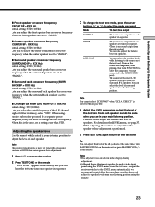
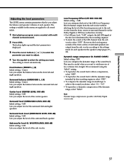
...each speaker. Low Frequency Effect (LFE MIX XXX dB) Initial setting : 0 dB Lets you attenuate the level of the LFE (Low Frequency Effect) channel output from the sub woofer, select "OFF". The settings available in small steps to all sound fields. 1 Start playing a program source encoded with Dolby Digital ... volumes late at the mix level determined by the recording engineer, select "STD". • To compress the dynamic range in this menu are output from the front, center or surround channels via the Dolby Digital or DTS bass redirection circuitry. • For LFE mix level, "0 dB...
...each speaker. Low Frequency Effect (LFE MIX XXX dB) Initial setting : 0 dB Lets you attenuate the level of the LFE (Low Frequency Effect) channel output from the sub woofer, select "OFF". The settings available in small steps to all sound fields. 1 Start playing a program source encoded with Dolby Digital ... volumes late at the mix level determined by the recording engineer, select "STD". • To compress the dynamic range in this menu are output from the front, center or surround channels via the Dolby Digital or DTS bass redirection circuitry. • For LFE mix level, "0 dB...


