
Limited Warranty (U.S. Only)
Page 1
... Product freight prepaid, in either its option, at no charge, or pay the labor charges to any authorized Sony service facility. This warranty does not cover customer instruction, installation, set up adjustments or signal reception problems. This warranty does not cover cosmetic damage or damage due to... LIMITED IN DURATION TO THE DURATION OF THIS WARRANTY. 4-557-173-02 General Stereo/Hifi Components/Tape Decks ® CD Players/Mini Disc Players/Audio Systems Hifi Audio LIMITED WARRANTY Sony Electronics Inc. ("Sony") warrants this Product is within 90 days of the date of sale, the...
... Product freight prepaid, in either its option, at no charge, or pay the labor charges to any authorized Sony service facility. This warranty does not cover customer instruction, installation, set up adjustments or signal reception problems. This warranty does not cover cosmetic damage or damage due to... LIMITED IN DURATION TO THE DURATION OF THIS WARRANTY. 4-557-173-02 General Stereo/Hifi Components/Tape Decks ® CD Players/Mini Disc Players/Audio Systems Hifi Audio LIMITED WARRANTY Sony Electronics Inc. ("Sony") warrants this Product is within 90 days of the date of sale, the...
Operating Instructions
Page 1
4-234-334-12(2) FM Stereo FM-AM Receiver Operating Instructions STR-DE975 STR-DE875 © 2001 Sony Corporation
4-234-334-12(2) FM Stereo FM-AM Receiver Operating Instructions STR-DE975 STR-DE875 © 2001 Sony Corporation

Operating Instructions
Page 2
... if not installed and used in accordance with the instructions, may be sure to use any question or problem concerning your receiver, please consult your dealer. • AC power ...intended to alert the user to persons. Reorient or relocate the receiving antenna. - STR-DE975/DE875 Serial No. Do not use the receiver for proper grounding and, in the United States and Canada ENERGY...your Sony dealer regarding this receiver at the rear of the receiver. • The unit is not disconnected from that might block the ventilation holes and cause malfunctions. • Although the receiver ...
... if not installed and used in accordance with the instructions, may be sure to use any question or problem concerning your receiver, please consult your dealer. • AC power ...intended to alert the user to persons. Reorient or relocate the receiving antenna. - STR-DE975/DE875 Serial No. Do not use the receiver for proper grounding and, in the United States and Canada ENERGY...your Sony dealer regarding this receiver at the rear of the receiver. • The unit is not disconnected from that might block the ventilation holes and cause malfunctions. • Although the receiver ...
Operating Instructions
Page 3
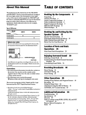
...of the rear panel (see the illustration below). Conventions • The instructions in the text, for example, "STR-DE975 only". All Rights Reserved. Type of differences Model Feature 5 audio inputs 4 audio inputs DE975 • DE875 • About area codes The area code of area code AA only... TABLE OF CONTENTS The instructions in this manual are for illustration purposes unless stated otherwise. In this manual, the STR-DE975 and the remote commander RM-PP505 are used in the text, for example, "Models of the receiver you purchased is used for the STR-DE975, and STR-DE875.
...of the rear panel (see the illustration below). Conventions • The instructions in the text, for example, "STR-DE975 only". All Rights Reserved. Type of differences Model Feature 5 audio inputs 4 audio inputs DE975 • DE875 • About area codes The area code of area code AA only... TABLE OF CONTENTS The instructions in this manual are for illustration purposes unless stated otherwise. In this manual, the STR-DE975 and the remote commander RM-PP505 are used in the text, for example, "Models of the receiver you purchased is used for the STR-DE975, and STR-DE875.
Operating Instructions
Page 9
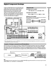
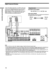
...be sure to match the color-coded pins to the instruction manual supplied with an RF OUT jack via an ... 120W/1A MAX AC 120V 60Hz AC OUTLET * When making connections as the Sony MOD-RF1 (not supplied). MODE 2CH ENTER MULTI /2CH A. Connect the LD...FM AM VIDEO L AUDIO R - SET UP NAME CINEMA STUDIO EX A B C DIGITAL CONCERT HALL 6.1 CH DECODING A B SOUND FIELD A.F.D. TUNING + - Hooking Up the Components Digital Component Hookups Connect the digital output jacks of your DVD player and satellite tuner (etc.) to the receiver's digital input jacks to the receiver...
...be sure to match the color-coded pins to the instruction manual supplied with an RF OUT jack via an ... 120W/1A MAX AC 120V 60Hz AC OUTLET * When making connections as the Sony MOD-RF1 (not supplied). MODE 2CH ENTER MULTI /2CH A. Connect the LD...FM AM VIDEO L AUDIO R - SET UP NAME CINEMA STUDIO EX A B C DIGITAL CONCERT HALL 6.1 CH DECODING A B SOUND FIELD A.F.D. TUNING + - Hooking Up the Components Digital Component Hookups Connect the digital output jacks of your DVD player and satellite tuner (etc.) to the receiver's digital input jacks to the receiver...
Operating Instructions
Page 10
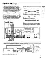
..., 44.1 kHz and 32 kHz sampling frequencies. Refer to the instructions supplied with your CD or SACD player and MD or DAT deck...is not possible to record analog signals to TAPE (STR-DE975 only), MD/DAT (STR-DE975 only) or MD/TAPE (STR-DE875 only) and VIDEO with 96 kHz sampling frequencies to ...DVD/LD IN L AM CONTROL A1 S-VIDEO OUT 2ND ROOM CTRL S IN COAXIAL FM 75Ω U L VIDEO OUT MONITOR R CTRL S S-VIDEO S-VIDEO CTRL ... AC 120V 60Hz AC OUTLET Notes • Please note that you to the receiver's digital output jack. ç ç Hooking Up the Components Digital Component ...
..., 44.1 kHz and 32 kHz sampling frequencies. Refer to the instructions supplied with your CD or SACD player and MD or DAT deck...is not possible to record analog signals to TAPE (STR-DE975 only), MD/DAT (STR-DE975 only) or MD/TAPE (STR-DE875 only) and VIDEO with 96 kHz sampling frequencies to ...DVD/LD IN L AM CONTROL A1 S-VIDEO OUT 2ND ROOM CTRL S IN COAXIAL FM 75Ω U L VIDEO OUT MONITOR R CTRL S S-VIDEO S-VIDEO CTRL ... AC 120V 60Hz AC OUTLET Notes • Please note that you to the receiver's digital output jack. ç ç Hooking Up the Components Digital Component ...
Operating Instructions
Page 11
... FM AM - Front Speaker (L) Front Speaker (R) Surround Speaker (L) Surround Speaker (R) Center Speaker Active Woofer 11 Alternatively, the MULTI CH IN jacks can connect them directly to the receiver to enjoy the sound of your surround speakers and sub woofer from the DVD player or multichannel decoder...) One for details on speaker system hookup. These connections allow you to connect an external multi channel decoder. Refer to the instruction manual supplied with your DVD player is also equipped with MULTI CH IN jacks. DIRECT EQUALIZER MUTING INPUT MODE MODE FUNCTION 2ND ...
... FM AM - Front Speaker (L) Front Speaker (R) Surround Speaker (L) Surround Speaker (R) Center Speaker Active Woofer 11 Alternatively, the MULTI CH IN jacks can connect them directly to the receiver to enjoy the sound of your surround speakers and sub woofer from the DVD player or multichannel decoder...) One for details on speaker system hookup. These connections allow you to connect an external multi channel decoder. Refer to the instruction manual supplied with your DVD player is also equipped with MULTI CH IN jacks. DIRECT EQUALIZER MUTING INPUT MODE MODE FUNCTION 2ND ...

Operating Instructions
Page 13
... shown below , input mode of the receiver to video input whenever you turn on the receiver. If, however, you have a Sony CD changer with VIDEO OUT jacks, set the command mode to "CD 1" and connect the changer to the VIDEO 2 jacks on page 53 and the operating instructions supplied with your CD player, SACD...
... shown below , input mode of the receiver to video input whenever you turn on the receiver. If, however, you have a Sony CD changer with VIDEO OUT jacks, set the command mode to "CD 1" and connect the changer to the VIDEO 2 jacks on page 53 and the operating instructions supplied with your CD player, SACD...

Operating Instructions
Page 17
... Speaker impedance Set the IMPEDANCE SELECTOR for the front speakers as indicated in the table below. Check the instruction manual supplied with your speakers if you turn off the receiver. After connecting all the speakers are touching each speaker cord does not touch another speaker terminal or the ...a test tone to take the following precautions when connecting the speakers. To avoid damaging your speaker is usually printed on a label on the receiver, the volume remains at the level you turn on the back of the speaker.) If the nominal impedance of Set IMPEDANCE SELECTOR to the...
... Speaker impedance Set the IMPEDANCE SELECTOR for the front speakers as indicated in the table below. Check the instruction manual supplied with your speakers if you turn off the receiver. After connecting all the speakers are touching each speaker cord does not touch another speaker terminal or the ...a test tone to take the following precautions when connecting the speakers. To avoid damaging your speaker is usually printed on a label on the receiver, the volume remains at the level you turn on the back of the speaker.) If the nominal impedance of Set IMPEDANCE SELECTOR to the...
Operating Instructions
Page 49
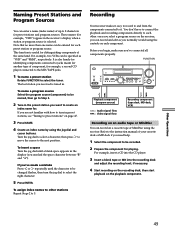
... CH DECODING A B SOUND FIELD A.F.D. To assign index names to other stations Repeat Steps 2 to each other: once you select a program source on the receiver, you can record and edit as "VHS" and "8MM", respectively. Before you begin, make sure you can find the space character between "??" FUNCTION ?.... 5 Press ENTER. TUNING + LEVEL SURR EQ MEMORY SHIFT FM MODE FM AM VIDEO L AUDIO R - Refer to the instruction manual of your cassette deck or MD deck if you are not familiar with how to tune in the receiver's display when a station or program source is tuned in the...
... CH DECODING A B SOUND FIELD A.F.D. To assign index names to other stations Repeat Steps 2 to each other: once you select a program source on the receiver, you can record and edit as "VHS" and "8MM", respectively. Before you begin, make sure you can find the space character between "??" FUNCTION ?.... 5 Press ENTER. TUNING + LEVEL SURR EQ MEMORY SHIFT FM MODE FM AM VIDEO L AUDIO R - Refer to the instruction manual of your cassette deck or MD deck if you are not familiar with how to tune in the receiver's display when a station or program source is tuned in the...
Operating Instructions
Page 50
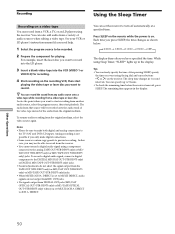
... recording. In this case, you want using Sleep Timer, "SLEEP" lights up to 5 hours. • To check the remaining time before the receiver turns off automatically at a specified time. DIRECT. You can also add audio from a variety of the audio from another audio source, select the program...source again. See your VCR or LD player's instruction manual if you press SLEEP, the time changes as shown below. Notes • Please be able to record from the TAPE OUT (STR-DE975 only) or MD/DAT OUT (STR-DE975 only) or MD/TAPE OUT (STR-DE875 only) jacks. • When MULTI/2CH A. ...
... recording. In this case, you want using Sleep Timer, "SLEEP" lights up to 5 hours. • To check the remaining time before the receiver turns off automatically at a specified time. DIRECT. You can also add audio from a variety of the audio from another audio source, select the program...source again. See your VCR or LD player's instruction manual if you press SLEEP, the time changes as shown below. Notes • Please be able to record from the TAPE OUT (STR-DE975 only) or MD/DAT OUT (STR-DE975 only) or MD/TAPE OUT (STR-DE875 only) jacks. • When MULTI/2CH A. ...
Operating Instructions
Page 53
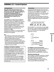
... components are supplied with your connection. For detailed information regarding particular connections or setup options, refer to the operating instructions supplied with no distinction of IN and OUT jacks. CONTROL A1 connections provide a path for each component. Components...connections. CONTROL A1 Control System Getting Started This section explains the basic functions of separate Sony components. However, when making connections between a Sony CD player, amplifier (receiver), MD deck and cassette deck provide automatic function selection and synchronized recording. If a ...
... components are supplied with your connection. For detailed information regarding particular connections or setup options, refer to the operating instructions supplied with no distinction of IN and OUT jacks. CONTROL A1 connections provide a path for each component. Components...connections. CONTROL A1 Control System Getting Started This section explains the basic functions of separate Sony components. However, when making connections between a Sony CD player, amplifier (receiver), MD deck and cassette deck provide automatic function selection and synchronized recording. If a ...
Operating Instructions
Page 54
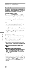
... selection When you connect a CONTROL A1 compatible Sony amplifier (or receiver) to other Sony components using a monaural mini-plug cord in order to take advantage of the function buttons. In this case, refer to the Operating Instructions supplied with the recorder component. 54 It will...released from the source component, recording stops. Notes • Do not set more than the recording source. Certain receivers allow you to the Operating Instructions supplied with a special synchronized recording function that uses the CONTROL A1 Control System, like "CD Synchro Dubbing". ...
... selection When you connect a CONTROL A1 compatible Sony amplifier (or receiver) to other Sony components using a monaural mini-plug cord in order to take advantage of the function buttons. In this case, refer to the Operating Instructions supplied with the recorder component. 54 It will...released from the source component, recording stops. Notes • Do not set more than the recording source. Certain receivers allow you to the Operating Instructions supplied with a special synchronized recording function that uses the CONTROL A1 Control System, like "CD Synchro Dubbing". ...


